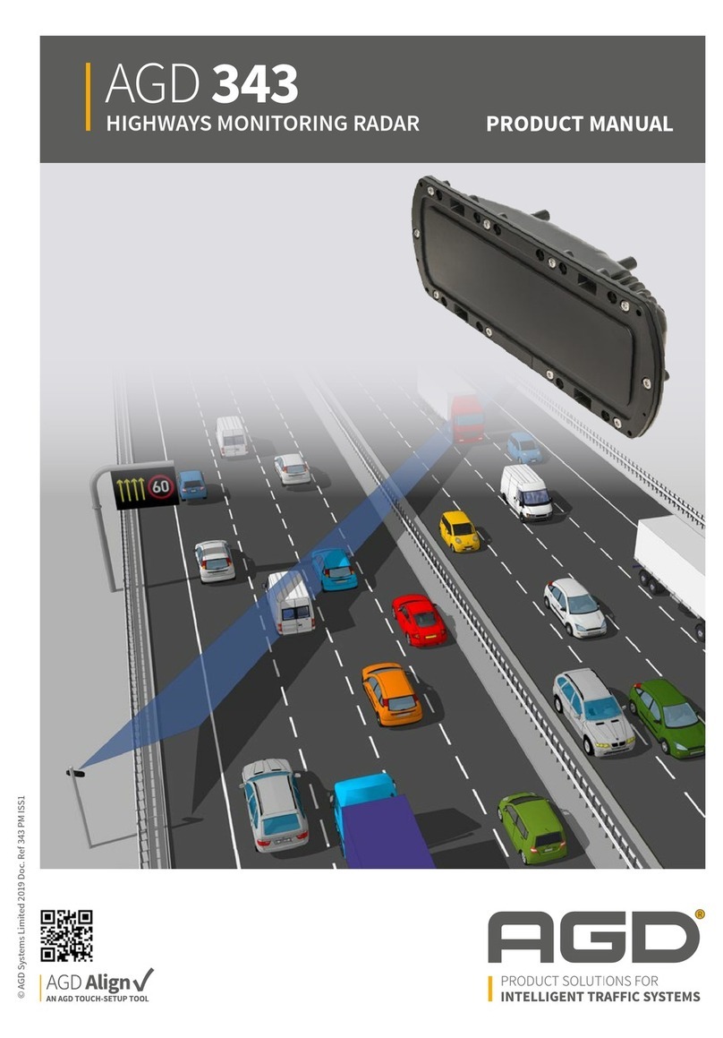
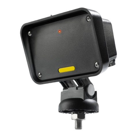
AGD 343 User manual

✓
PRODUCT MANUAL
© AGD Systems Limited 2019 Doc. Ref 343 PM ISS1
AGD 343
HIGHWAYS MONITORING RADAR
AGD 343
HIGHWAYS MONITORING RADAR
AGD 343
HIGHWAYS MONITORING RADAR
AGD 343
HIGHWAYS MONITORING RADAR

2
AGD 343
HIGHWAYS MONITORING RADAR
AGD 343
HIGHWAYS MONITORING RADAR
AGD 343
HIGHWAYS MONITORING RADAR
AGD 343
HIGHWAYS MONITORING RADAR
INTRODUCTION 2
Product and Technology 3
Key Features 3
Typical Applications 4
Product Overview 5
INSTALLATION 6
Installation Information 6
Mounting Location 7
Physical Installation 8 - 10
Electrical Installation 11
Power and Communications 12 - 21
INSTALLATION AND COMMISSIONING 22
Camera Connection 22 - 23
WiFi Connection 23
AGD Align Set-Up Tool 24 - 37
Radar Command Overview 38
MESSAGE FORMATS 42
Radar Event Messages - Heart Beat 42
Radar Event Messages - ES, EP, EE 43
Radar Event Messages - Examples 44
User Event Messages 45 - 46
Data Record Messages 47
Data Record Messages - Examples 48
TROUBLE SHOOTING 49
Physical Installation 49
Electrical Installation 49
Connecting / Commissioning 49
RADAR CHARACTERISTICS 50
Operating Frequency Band and Power 50
TECHNICAL SPECIFICATIONS 51
Product Dimensions 51
CERTIFICATION 52
END OF LIFE - DISPOSAL INSTRUCTIONS (EOL) 53
IMPORTANT SAFETY INFORMATION 54
Safety precautions 54
Low power non-ionising radio transmission
and safety 55
DISCLAIMER 60
Warranty 60
Contact Details 60
Table of Contents
safer, greener, more eicient

3
AGD 343
HIGHWAYS MONITORING RADAR
AGD 343
HIGHWAYS MONITORING RADAR
AGD 343
HIGHWAYS MONITORING RADAR
AGD 343
HIGHWAYS MONITORING RADAR
Introduction
PRODUCT & TECHNOLOGY
KEY FEATURES
• Flow monitoring solution for multi-lane real-time data
• Traffic Profiling and Incident Detection
• Ten lane highway capability
• Enforcement grade radar & techniques
• Identifies, tracks & measures speed, length, lane/direction of individual targets
• Multi-level incident detection mode
• Non-intrusive loop replacement
• Mounts on existing infrastructure
• Simple to install, setup and configure using AGD Align
The AGD 343 Highways Monitoring Radar is an easy-to-
integrate traic ow monitoring solution that provides
real-time data on multi-lane highways. Designed for traic
proling and incident detection, the 343 dramatically
enhances highways safety, capability and eiciency.
AGD’s 343 employs proven enforcement-grade radar &
measurement techniques to quantify speed, range and
length of passing vehicles. Detailed traic information
- such as, ‘is traic free-moving, slowing or starting-to-
queue?’ - is available in all weather conditions to inform
control rooms and allow instant decision making.
AGD radar can replace intrusive high-maintenance loops,
mounting on existing roadside poles or gantries where
it ‘looks’ across the road at 30 degrees. The additional
capability to operate at a ≥ 2-metre oset, while
maintaining a 6-metre plus mounting height, ensures
reliable operation in managed motorway scenarios and
ALR (All Lanes Running) schemes. The 343 has been
designed to cope with the many diiculties
facing international road network installations.

4
AGD 343
HIGHWAYS MONITORING RADAR
AGD 343
HIGHWAYS MONITORING RADAR
AGD 343
HIGHWAYS MONITORING RADAR
AGD 343
HIGHWAYS MONITORING RADAR
Introduction
TYPICAL APPLICATIONS
Multi-Lane Highways Monitoring Radar - Dedicated Infrastructure Mounted
MS4 Mounted Gantry Mounted

5
Flange Mounting
Points
AGD 343
HIGHWAYS MONITORING RADAR
AGD 343
HIGHWAYS MONITORING RADAR
AGD 343
HIGHWAYS MONITORING RADAR
AGD 343
HIGHWAYS MONITORING RADAR
PRODUCT OVERVIEW
Power/RS422 Cable
Connector Port
Bracket Fixing
Points
Introduction
safer, greener, more eicient

6
AGD 343
HIGHWAYS MONITORING RADAR
AGD 343
HIGHWAYS MONITORING RADAR
AGD 343
HIGHWAYS MONITORING RADAR
AGD 343
HIGHWAYS MONITORING RADAR
INSTALLATION INFORMATION
The radar is designed to be mounted to various structures such as a dedicated column, gantry or sign.
To install the radar, the following parts will be required:
To provide power and communication interfaces the following parts will assist in detector integration:
Installation
No. Part No Description Notes
1 343-500-000 AGD 343 Highways Monitoring Radar
2 MS-246 343 Mounting Bracket Kit
3 CA-310 343 Power/RS422 Cable Assembly
4 MK343-05 Camera Setup Tool (this is removed after setup)
No. Part No Description Notes
5 MK343-01 343 Interface Enclosure
6 MK343-03 343 Interface Enclosure (c/w 24Vdc PSU)
1
4
2
5
3
6

7
AGD 343
HIGHWAYS MONITORING RADAR
AGD 343
HIGHWAYS MONITORING RADAR
AGD 343
HIGHWAYS MONITORING RADAR
AGD 343
HIGHWAYS MONITORING RADAR
MOUNTING LOCATION
The AGD 343 has been designed to be mounted on a variety of structures, where it looks across the carriageway
The detector must be mounted at a minimum height of 6m above the carriageway and at an angle of
30 degrees. The AGD Align set-up tool assists in accurate set up of the angle.
Mounting Location Considerations
Avoid where possible:
retaining walls)
Installation
Offset Recommended Mounting Height Acceptable Mounting Height
2m 6m 6m
Oset: 2 metres
Height: 6 metres
Setup: AGD Align Visual
& Histogram
2 m
30º
CONFIGURATION:
6 m
Oset: 2 metres
Height: 6 metres
Setup: AGD Align Visual
& Histogram
2 m
30º
CONFIGURATION:
6 m

8
s
DIRECTION OF TRAVEL
s
DIRECTION OF TRAVEL
Pole
Pole
AGD 343
HIGHWAYS MONITORING RADAR
AGD 343
HIGHWAYS MONITORING RADAR
AGD 343
HIGHWAYS MONITORING RADAR
AGD 343
HIGHWAYS MONITORING RADAR
PHYSICAL INSTALLATION
343 Mounting Bracket Kit
The AGD 343 bracket mounting kit (part number MS-246
hardware.
BR-270 is the component of the bracket kit that BR-271 is the component of the bracket kit that
Fixing hardware consists of:
7no. M5 x 10mm Torx T20 A2 Stainless Screws
7no. M5 External Shakeproof A2 Stainless Washers
Step 1 – Mount bracket to the pole
Installation
Attach BR-270 to the structure you are mounting too
using mounting straps (AGD recommends stainless
steel sign banding ½” thick).
The position of the bracket should be parallel to the
the bracket as shown in the right hand image.

9
AGD 343
HIGHWAYS MONITORING RADAR
AGD 343
HIGHWAYS MONITORING RADAR
AGD 343
HIGHWAYS MONITORING RADAR
AGD 343
HIGHWAYS MONITORING RADAR
30º Mark
PHYSICAL INSTALLATION
Step 2 – Mount bracket to the radar
Fit the six torx screws and washers and
tighten to a torque of 1.2Nm.
with the cable entry port of the radar
pointed downward and the bracket not
obscuring it.
Step 3 – Mount radar to the pole
Insert the M10 Mounting Bolt through
the hole in the bracket on the pole,
loosely tighten the M10 Nyloc Nut.
Install the M5 locking nut in the slot
as shown adjacent to the M10 captive
bolt.
Position the radar at roughly
30 degrees to the road, the etched
marks on top of the bracket will help
with alignment.
Installation

10
AGD 343
HIGHWAYS MONITORING RADAR
AGD 343
HIGHWAYS MONITORING RADAR
AGD 343
HIGHWAYS MONITORING RADAR
AGD 343
HIGHWAYS MONITORING RADAR
PHYSICAL INSTALLATION
Step 4 – Install cable
Install the cable in a suitable manner
down through the pole by drilling and
always inserting the cable through a
suitable grommet.
Connect the cable to the cable entry
port on the bottom of the radar.
Step 5 – Install MK343-03 Interface
Enclosure (c/w 24Vdc PSU)
Using the same method that was used
to mount the radar bracket to the pole,
mount the interface enclosure using
stainless steel banding.
The box has an IP56 rating.
Installation
ss

11
AGD 343
HIGHWAYS MONITORING RADAR
AGD 343
HIGHWAYS MONITORING RADAR
AGD 343
HIGHWAYS MONITORING RADAR
AGD 343
HIGHWAYS MONITORING RADAR
CONNECTIONS
Pin No. Associated wire colour Function Additional Notes
1 White GND (0v)
2 Brown GND (0v)
3 Green Y (TX+)
4 Yellow Z (TX-)
5Grey B (RX-)
6 Pink A (RX+)
7 Blue Vin
8Red Vin
5
8
6 4
7 3
1 2
ELECTRICAL INSTALLATION
The detector is powered using a 12-24Vdc supply. The power is applied to the detector using the multi-pin
mating connector.
The product mating connector is shown above and is located on the bottom of the product.
343 Power/RS422 Cable Assembly
The cable assembly to connect power and comms to the radar is Part Number CA-310. This cable is supplied in
a 10m length and is shown below:
CA-310 has the same attributes as shown in the Connections table above.
Installation

12
AGD 343
HIGHWAYS MONITORING RADAR
AGD 343
HIGHWAYS MONITORING RADAR
AGD 343
HIGHWAYS MONITORING RADAR
AGD 343
HIGHWAYS MONITORING RADAR
1
2
3
Typical installation with MK343-03 Interface
Enclosure (c/w 24Vdc PSU)
Installation
POWER AND COMMUNICATIONS
Installation with Interface Enclosure
The radar can be powered and communicated with as
AGD provides a series of equipment to support simple
integration into the road network and line protection
for connected equipment.
The unit can be installed with or with out existing
roadside network infrastructure, so the device can be
installed in most situations.
AGD provide a 343 interface enclosure complete
with power, communications and line protection to
connect the detector.
Part No. MK343-03 - 343 Interface Enclosure
(c/w 24Vdc PSU)
The detector, bracket and interface enclosure are
secured to the pole using stainless steel banding
as described previously.
Cable entry glands are provided for the customer to
provide power to the device and connect the CA-310
Power/RS422 cable assembly.
*Note* The interface enclosure is delivered with
Items shown in diagram:
1. AGD 343 Highways Monitoring Radar
2. MS-246 Bracket Kit
3. MK343-03 Interface Enclosure (c/w 24Vdc PSU)

13
AGD 343
HIGHWAYS MONITORING RADAR
AGD 343
HIGHWAYS MONITORING RADAR
AGD 343
HIGHWAYS MONITORING RADAR
AGD 343
HIGHWAYS MONITORING RADAR
MK343-03 Interface Enclosure (c/w 24Vdc PSU)
INSTALL CA-310 RADAR CABLE HERE
1
Installation
POWER AND COMMUNICATIONS
Interface Enclosure Components:
1. 110v-230Vac to 24Vdc PSU
2. RS422 Communications Interface Board
3. Incoming Power Connections
4. Radar Cable Connector
5. External Equipment Connector
Connecting the Radar
The radar is connected to the ‘TOP’ of the two
connectors situated on the right hand side of the
interface enclosure. This is an 8 way screw connector
and the connections are listed below, from top to
bottom. The screw connector pulls out from it’s
receptacle to be wired.
The interface enclosure is pre-wired internally so only
external connections are required.
3
1
2
4
5
CONNECTIONS
Pin No. Associated wire colour Function
8 Pink (RX+)
7Grey (RX-)
6 Yellow (TX-)
5 Green (TX+)
4 Blue Vin
3Red Vin
2 Brown Gnd
1 White Gnd

14
AGD 343
HIGHWAYS MONITORING RADAR
AGD 343
HIGHWAYS MONITORING RADAR
AGD 343
HIGHWAYS MONITORING RADAR
AGD 343
HIGHWAYS MONITORING RADAR
LIVE
NEUTRAL
EARTH
Incoming Power Connections and PSU
MK343-03 Interface Enclosure (c/w 24Vdc PSU)
INSTALL INCOMING POWER HERE
Installation
POWER AND COMMUNICATIONS
Connecting the Power
The MK343-03 Interface Enclosure has DIN rail
mounted connectors for connection to mains power.
The ‘Live’ cable entry point incorporates a 0.5A
thermal overload.
The cables are connected as shown below.
*Electrical installation should be carried out in
accordance with local regulations.
DC Power Supply
The power supply included as part of MK343-03 Interface Enclosure has spare capacity to allow for the user to
connect some extra equipment. Information is detailed below:
Input Voltage Range: 85-264Vac
Output Range: 24Vdc, 1.25A, 30W
Spare capacity: Startup current should be considered but spare capacity is around
15W, with one 343 radar connected.

15
AGD 343
HIGHWAYS MONITORING RADAR
AGD 343
HIGHWAYS MONITORING RADAR
AGD 343
HIGHWAYS MONITORING RADAR
AGD 343
HIGHWAYS MONITORING RADAR
*PLUG EXTERNAL KIT/
CONNECTIONS HERE*
MK343-03 Interface Enclosure (c/w 24Vdc PSU)
1
Installation
POWER AND COMMUNICATIONS
Connecting External Equipment
External equipment can be connected to the external
equipment connector 1.
Whether this be an external ground cable as
referenced in the next section ‘Installation with
Interface Enclosure & Rack Mounted Equipment’,
or the connection of an integrators equipment to
communicate with the radar.
Integrator equipment should be connected via the
external equipment connector as per the pin outs
below.
*Important to note, when connecting external
equipment, the RS422 functions will need to be
reversed respectively*
CONNECTIONS
Pin No. Associated wire colour Function
6 Blue (RX-)
5 Brown (RX+)
4 Orange (TX-)
3 Yellow (TX+)
2Red Vin
1 Black Gnd
1
CONNECT EXTERNAL
EQUIPMENT HERE

16
AGD 343
HIGHWAYS MONITORING RADAR
AGD 343
HIGHWAYS MONITORING RADAR
AGD 343
HIGHWAYS MONITORING RADAR
AGD 343
HIGHWAYS MONITORING RADAR
SW2
SW4
MK343-03 Interface Enclosure (c/w 24Vdc PSU) RS422 Communications Interface Board
7
1
2
3
4
5
6
Installation
POWER AND COMMUNICATIONS
RS422 Communications Interface Board
The RS422 communications interface board forms
part of the MK343-03 Interface Enclosure. It handles
the task of allowing multiple data connections to
interfacing to equipment and provides important
surge protection for connected devices.
RS422 Communications Interface Board - Overview
1. RJ11 socket sits on ‘Link 1’, directly connected to item 2.
2. Pre-wired connection to the radar cable connector. This connection sits on ‘Link 1’
and is directly connected to item 1.
3. Dip switch SW4, controls the speed of the data on ‘Link 1’.
4. Dip switch SW2, controls the operating mode of the board and the speed of the data on ‘Link 2’.
5. Screw connector sits on ‘Link 3’, directly connected to item 6.
6. RJ11 socket sits on ‘Link 3’, directly connected to item 5.
7. Pre-wired connection to the external equipment connector. This connection sits on ‘Link 3’.

17
AGD 343
HIGHWAYS MONITORING RADAR
AGD 343
HIGHWAYS MONITORING RADAR
AGD 343
HIGHWAYS MONITORING RADAR
AGD 343
HIGHWAYS MONITORING RADAR
SW2
SW4
SW2
SW4
RS422 Communications Interface Board
LINK 1
LINK 1
LINK 2
LINK 2
LINK 3
LINK 3
Installation
POWER AND COMMUNICATIONS
RS422 Communications Interface Board - Detailed Operation
The RS422 Interface board connects the various ports as
descibed below. Understanding this is very important when
connecting to the radar to commission the device or when
integrating other equipment.
LINK 1 - Pre-wired to radar cable connector, both ports
joined.
LINK 2 - External link pre-wired to external equipment
connector.
LINK 3 - Debug port connections, both ports joined.
A. All data recieved on LINK 1 shall be passed out on LINK 3.
All data recieved on LINK 3 shall be passed out on LINK 1.
B. All data recieved on LINK 2 shall be passed out on LINK
message before being passed out on LINK 2.
A
B

18
AGD 343
HIGHWAYS MONITORING RADAR
AGD 343
HIGHWAYS MONITORING RADAR
AGD 343
HIGHWAYS MONITORING RADAR
AGD 343
HIGHWAYS MONITORING RADAR
SW2
SW4
RS422 Communications Interface Board
SW2
SW4
654321
123456
654321
123456
RJ11 Male Pin-outs RJ11 Female Pin-outs
*RS422 CONFIG PLUG IN HERE*
LINK 3
P4
J3
Installation
POWER AND COMMUNICATIONS
RS422 Communications Interface Board - Debug Port Link
LINK 3 is the dedicated debug port link. This allows the
radar to remain connected on ‘LINK 1’ to talk to external
equipment on ‘LINK 2’ and a further connection be launched
on ‘LINK 3’.
LINK 3 - Hardwiring (P4 Connector)
To hardwire to LINK 3 via P4 connector, use the following pin outs:
LINK 3 - J3 (RJ11) Connector
The pinouts shown correspond to the numbers highlighted on both the female and male plugs. Construction of
a male connector is required should the end user want to use a RS422-USB converter of their own choice.
Part No. CA-345 USB-422 343 Conguration Cable
*IMPORTANT NOTE - These functions are correct at the relevant connectors.
LINK 3 CONNECTIONS
Pin No. Function
1 (RX+)
2 (RX-)
3 (TX+)
4 (TX-)
5 Gnd
LINK 3 - J3 (RJ11) CONNECTIONS
Pin No. Function
1 (RX+)
2 (TX+)
3 (TX-)
4 (RX-)
5 Gnd
6 Gnd

19
AGD 343
HIGHWAYS MONITORING RADAR
AGD 343
HIGHWAYS MONITORING RADAR
AGD 343
HIGHWAYS MONITORING RADAR
AGD 343
HIGHWAYS MONITORING RADAR
SW2
SW4
RS422 Communications Interface Board
off
on
off
on
off
on
off
on
off
on
off
on
Installation
POWER AND COMMUNICATIONS
RS422 Communications Interface Board - Dip Switches
RS422 Communications Interface Board - Setting Dip Switches
The dip switches SW2 and SW4 control the operating mode of the board and the data rates of the equipment
*SW2 can be set as per the table on the right. Recommended values are highlighted in orange and shown in
actual postitions below.
SW2 - DIP SWITCH SETTINGS
SW 2-1 Operating Mode
Mode 1
On Mode 2
SW2 - DIP SWITCH SETTINGS
SW 2-2 SW 2-3 Link 2 Speed
9600
On 19200
On 38400
On On 115200

20
AGD 343
HIGHWAYS MONITORING RADAR
AGD 343
HIGHWAYS MONITORING RADAR
AGD 343
HIGHWAYS MONITORING RADAR
AGD 343
HIGHWAYS MONITORING RADAR
SW2
SW4
LINK 1
LINK 2 LINK 3
off
on
off
on
off
on
921600 bps TX & RX
to RADAR on LINK 1
921600 bps TX & RX
to RADAR via LINK 3
DEBUG Connection
115200 bps TX & RX to
RADAR via LINK 2 External
Equipment Connection
Installation
POWER AND COMMUNICATIONS
RS422 Communications Interface Board - Setting Dip Switches
SW4 controls the BAUD rate of LINK 1 and LINK3. The LINKS
operate at the same data rate. SW4 can be set as per the table
below. Recommended values are highlighted in orange and
RS422 Communications Interface Board - Data Rate Overview and Connections
SW4 - DIP SWITCH SETTINGS
SW 4-1 SW 4-2 SW 4-3 Link 1 & 3 Speed
9600
On 19200
On 38400
On On 57600
On 115200
On On 230400
On On 460800
On On On 921600
Other manuals for 343
1
Table of contents
Other AGD Radar manuals
Popular Radar manuals by other brands

Endress+Hauser
Endress+Hauser Micropilot M FMR240 operating instructions

Ainstein
Ainstein WAYV Pro installation instructions

Bindicator
Bindicator TDR-1000 quick start guide

Houston Radar
Houston Radar PD300 User manual and installation guide

Magnetrol
Magnetrol Pulsar Foundation fieldbus R96 operating manual

Autel
Autel ASR100 user manual