AGI EZTest Hazmon User manual

EZTest
HazMon System Tester
mDT001
EZTest
HazMon System Tester
Document No. 11584, Revision A06
January 2019

This page intentionally left blank.

mDT001 HazMon System Tester Technical Manual /i
CMC INDUSTRIAL ELECTRONICS LTD
Phone: (604) 421-4425 Toll Free: (888) 421-4425 Fax: (604) 421-7734
The Industry Leader in HazMon Technology
Table of Contents
1. Overview..............................................................................................................................1
2. Description of Indicators ......................................................................................................3
3. Operation.............................................................................................................................5
3.1 Using the Menu Control Pushbuttons............................................................................6
3.2 Sensor Test..................................................................................................................7
3.3 Bus Test .....................................................................................................................12
3.4 Sensor Emulator.........................................................................................................15
3.5 Sensor Configuration..................................................................................................17
3.5.1 Configuration of mTS017, mVM001, mCP001 and mPTH001.............................17
3.5.2 Configuration of digital grain cable.......................................................................18
3.6 Battery Gauge ............................................................................................................21
3.7 Proximity Data ............................................................................................................22
3.8 Cable Insert Test CMC internal use only.....................................................................23
4. Troubleshooting Tips .........................................................................................................24
5. Troubleshooting charts ......................................................................................................25
6. Specifications.....................................................................................................................27
Appendix 1................................................................................................................................28
Table of Figures
Figure 1 - Illustration of Indicators...............................................................................................3

mDT001 HazMon System Tester Technical Manual /ii
CMC INDUSTRIAL ELECTRONICS LTD
Phone: (604) 421-4425 Toll Free: (888) 421-4425 Fax: (604) 421-7734
The Industry Leader in HazMon Technology
Revision Notes
First Release –October 18, 2012
Revision A01 –January 16, 2013
•Update to include version 1.02 firmware features
Revision A02 –April 2, 2015
•Rewrite the firmware from assembly language to C language, and update firmware to
V2.00
•Support all test functions in Revision A01, and add function to test mCP001 and mIP001
sensors
Revision A03 –February 1, 2017
•Add the function to read mDC001 sensors
•Add the function to configure mDC001 cables
•Add the function to detect the number of DS28EA00 sensors connected on a cable
Revision A04 –June 12, 2017 –FW 2.26
•Update to include version 2.26 firmware features
•Change batter gauge function to batter voltage function
•Modify mDC001 cable configuration to configure CMC cable and OPI cable
Revision A05 –March 20, 2018 –FW 2.33
•Sensor test description for mDC002 added
•Grain cable configuration added
•Proximity data on mCP001 added
•Battery gauge modified
•Ground fault removed from testing
•mPHT001 sensor added
Revision A06 –January 31, 2019 –FW 2.33
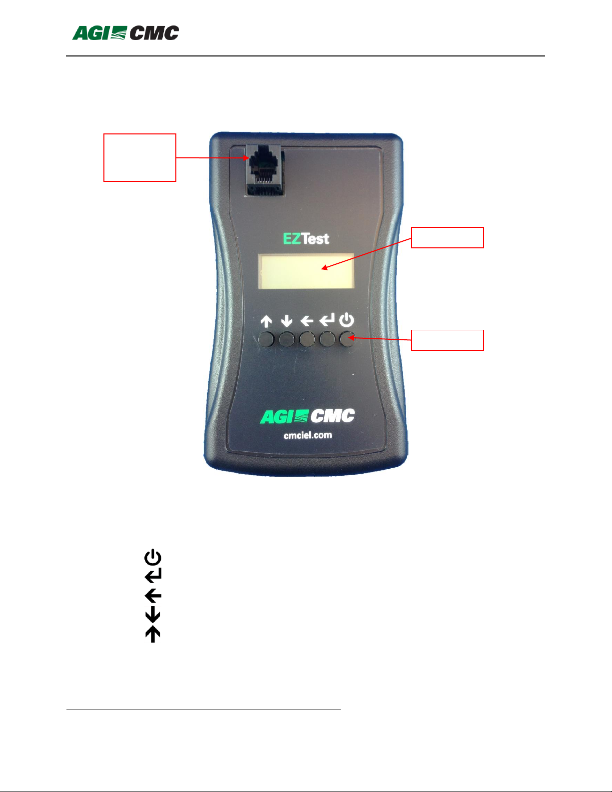
•New overlay, logo and buttons

mDT001 HazMon System Tester Technical Manual /iii
CMC INDUSTRIAL ELECTRONICS LTD
Phone: (604) 421-4425 Toll Free: (888) 421-4425 Fax: (604) 421-7734
The Industry Leader in HazMon Technology

mDT001 HazMon System Tester Technical Manual /1
CMC INDUSTRIAL ELECTRONICS LTD
Phone: (604) 421-4425 Toll Free: (888) 421-4425 Fax: (604) 421-7734
The Industry Leader in HazMon Technology
1. Overview
The EZTest HazMon System Tester provides a simple method to diagnose CMC HazMon
systems.
The EZTest is handheld and operates off 2 AA batteries. It has an easy to read backlit LCD. A
simple 4 button operator interface is provided
The EZTest provides a standalone good/bad test for individual sensors. In addition, the
sensor’s electrical interface and real-time output can be verified. All information is presented in
scaled units to simplify the test results.
In addition to testing individual sensors, the EZTest can be connected to an active CMC
Intrinsically Safe network. The EZTest will supply a simply good/bad indication of the networks
operation. Further details of the networks electrical operating condition are also provided.
The EZTest can also emulate a sensor. A sensor is first attached to the EZTest and after the
serial number is captured the EZTest is attached to the network. The keyboard can then be
used to set any value for the sensor.
mVM001 Vibration Sensor, mTS017 Infrared Temperature Sensor, mCP001 Proximity
Capacitive Sensor, mIP001 Proximity Inductive Sensor, mDC001/2 Cable Sensor and
mPHT001 Pressure Humidity Temperature Sensor are configurable. The EZTest provides a
simplified means of configuring these sensors.

mDT001 HazMon System Tester Technical Manual /2
CMC INDUSTRIAL ELECTRONICS LTD
Phone: (604) 421-4425 Toll Free: (888) 421-4425 Fax: (604) 421-7734
The Industry Leader in HazMon Technology
This page intentionally left blank.

mDT001 HazMon System Tester Technical Manual /3
CMC INDUSTRIAL ELECTRONICS LTD
Phone: (604) 421-4425 Toll Free: (888) 421-4425 Fax: (604) 421-7734
The Industry Leader in HazMon Technology
2. Description of Indicators
Figure 1 - Illustration of Indicators
There are five control pushbuttons:
Power
Press to turn power on or off
Select
Select the displayed function
Back
Go back one menu level or exit this function
Down
Next menu item; Decrease value
Up
Previous menu item; Increase value
Sensor or
Bus Cable
Connector
Display
Keyboard

mDT001 HazMon System Tester Technical Manual /4
CMC INDUSTRIAL ELECTRONICS LTD
Phone: (604) 421-4425 Toll Free: (888) 421-4425 Fax: (604) 421-7734
The Industry Leader in HazMon Technology
This page intentionally left blank.

mDT001 HazMon System Tester Technical Manual /5
CMC INDUSTRIAL ELECTRONICS LTD
Phone: (604) 421-4425 Toll Free: (888) 421-4425 Fax: (604) 421-7734
The Industry Leader in HazMon Technology
3. Operation
The EZTest HazMon System Tester has an easy to use menu system. To turn on the tester,
press and hold the <Power>key until the display backlight illuminates. To turn the tester off,
press and hold the <Power>key until the display backlight goes off. The tester automatically
turns off after 5 minutes except working in “Sensor Emulator” mode:
The system will display two opening messages when power is turned on:
The tester may display a status message before proceeding to the main menu. The status
messages are as follows:
Message
Description
Required Action
Battery Low
< 2.20V
The battery has discharged
below 2.20 V
Check the battery level using the
“Battery Voltage” function. If the
voltage is less than 2.20V, replace the
batteries
Program CRC
Fault
The tester’s program is
corrupted
Return the unit to the factory for repair
Data RAM
Fault
The tester failed self-test
Return the unit to the factory for repair
Calibration
Fault
The calibration parameters
are corrupted
Return the unit to the factory for repair
The main menu is then displayed:
CMC Industrial
Electronics
EZTest Ver 2.33
Copyright 2018
Select Function
Sensor Test

mDT001 HazMon System Tester Technical Manual /6
CMC INDUSTRIAL ELECTRONICS LTD
Phone: (604) 421-4425 Toll Free: (888) 421-4425 Fax: (604) 421-7734
The Industry Leader in HazMon Technology
3.1 Using the Menu Control Pushbuttons
There are four menu control pushbuttons:
Select
Select the displayed function
Back
Go back one menu level or exit this function
Down
Next menu item
Up
Previous menu item
There are six menu selections from the main menu. These are selected using the Up and
Down pushbuttons.
Sensor Test
Test an individual sensor
Bus Test
Test the CMC Intrinsically Safe network
Sensor Emulator
Emulates connected sensor
Sensor Configuration
Configure sensor parameters
Battery Voltage
Check remaining battery level
Proximity Data
Read proximity data for mCP001 Sensor
Cable Insert Test
Read number of sensors connected on the
cable insertion FOR CMC INTERNAL USE
ONLY
Once the function is displayed, it is executed by pressing the <Select> pushbutton.

mDT001 HazMon System Tester Technical Manual /7
CMC INDUSTRIAL ELECTRONICS LTD
Phone: (604) 421-4425 Toll Free: (888) 421-4425 Fax: (604) 421-7734
The Industry Leader in HazMon Technology
3.2 Sensor Test
The sensor test will report the health of a single sensor plugged into the modular connector on
the front of the unit. In addition, the sensor test will check for any fault conditions of the actual
sensor and on the sensor wiring.
Note: EZTester itself doesn’t work as a tester for any type of digital grain temperature cables.
Correct reading of grain cable on EZTester is not indication of good condition of the cable.
Grain cable can be tested by EZTester when using together with mDC controller described
below.
************************************************ Caution *************************************************
Sensors connected to a bus converter on an active network or multiple sensors connected
together cannot be tested using this function. Connect a single standalone sensor into the
tester’s front panel connector.
************************************************************************************************************
If “Sensor Test” is selected and no sensor is connected to the modular connector, the display
will indicate:
To test a sensor, plug the sensor into the tester. When a sensor is connected to the modular
jack and “Sensor Test” is selected, the display will first indicate:
The following messages can be displayed:
Message
Description
Sensor Good
The sensor passed all of the tests and is operational. This test
confirms the electrical interface of the sensor is working
properly. Use the Down key to verify the sensor is providing
the correct output.
Supply Volts Low
The sensor is drawing too high a current from the networks
power supply.
Sensor Test
No Sensor
Sensor Test
Please Wait

mDT001 HazMon System Tester Technical Manual /8
CMC INDUSTRIAL ELECTRONICS LTD
Phone: (604) 421-4425 Toll Free: (888) 421-4425 Fax: (604) 421-7734
The Industry Leader in HazMon Technology
Data Volts High
The sensor is loading the data line and the data high voltage
is lower than required.
Data Volts Low
The sensor is loading the data line and the data line low
voltage is higher than allowed.
Open Wire
For temperature sensors this message indicates that the red
power wire to the sensor is open
Bad Data
The tester was unable to read a valid data packet from the
sensor.
No Sensor
No sensor was detected, the sensor is defective
Serial Number
Sensor’s serial number can be read if there is valid sensor
connected
Measured Value
Sensor’s measurement value can be read if there is valid
sensor connected. When mTC002 and mDC001/2 cards are
tested the values of connected cables can be read, described
below.
Firmware Version
Sensor’s firmware can be read if there is valid mCP001 or
mIP001 sensor connected
The <Up>and <Down> keys can be used to display further information about the sensor’s
performance. If the display indicates “Sensor Good”, use the <Down> key to verify the value
being returned by the sensor. The tester displays the sensor’s value in real world units for
verification.
The following table describes the available display starting from the status display described
above:
Key
Function
Description
Down 1
Real-time display
The sensor type and real-time value for the sensor are
displayed in the units suitable for the sensor. Verify the
sensor’s output using this function.
Down 2
Serial number display
The sensor’s serial number is displayed. The serial
number should agree with the serial number printed on
the sensor’s label.
Down 3
Sensor Version
Sensor version is displayed. This function is only valid
for mCP001 and mIP001 sensors
Up 1
Sensor Power
The sensor power voltage level is displayed. If this
voltage is too low it indicates the sensor is drawing
excessive power.
Up 2
Sensor Data Low
The data low voltage level on the network is displayed. If
this voltage is too high, the sensor has resistance
between the green data wire and the red power wire.

mDT001 HazMon System Tester Technical Manual /9
CMC INDUSTRIAL ELECTRONICS LTD
Phone: (604) 421-4425 Toll Free: (888) 421-4425 Fax: (604) 421-7734
The Industry Leader in HazMon Technology
Up 3
Sensor Data High
The data high voltage level on the network is displayed.
If this voltage is too low the sensor has resistance
between the green data wire and the white common
wire.
Sensor test on mTC002 and mDC002
To perform this test the tester must be connected to single controller card connected to the
backplane and cables which should be read are connected to designated terminals. No more
than one controller card can be read at the same time. The card needs to be isolated from a
system if installed in one. It is enough to disconnect incoming and outgoing branches using the
dip switches on backplanes.
mTC002
If the card works correctly and Real-time display menu in sensor test is selected the tester will
circle between the mTC002 card status (see mTC002 manual for more information on status),
ambient temperature of the board and then values of connected thermocouple sensors. It takes
time for the mTC002 card to provide the data so it circles between status and ambient
temperature for a while. It depends on position of thermocouple sensors how it will be
displayed. If 7 thermocouple sensors are connected to the first card and first connector the
sensors will be reported under numbers 1-7 as on example below:
The same will be read if the connector on the mTC002-TC is closed and if there is no sensor
connected and the switch is open the display will show error for open wire.
mDC002
If the card works correctly and Real-time display menu in sensor test is selected the tester will
circle right away between the controller card status, ambient temperature and the values from
the connected sensors.
The test of the mDC002 by EZTester is more sophisticated than on the mTC002 and can help
to troubleshoot the card with the sensor cables. The EZTester only reads data provided by the
mDC002 card and detailed description of the data is in manual of the mDC002. Description
below shows just the interpretation of the data on the EZTester.
Status
Of mDC card
Message
Description
OK!
No problem, everything is working good.
F
ROM memory problem, card should be replaced
P
Power up problem, card should be replaced
S
Presence of short on one of the cables
A
Ambient temperature sensor on card failure
O
One of previously read cables is disconnected
Cables
Reading
Each cable read temperature in °C and °F and is represented by a number. The
number shows the position of each sensor. If the cable has 20 sensors and it is
mTC002
1 23°C 73°F
mTC002
2 25°C 77°F
mTC002
3 24°C 75°F

mDT001 HazMon System Tester Technical Manual /10
CMC INDUSTRIAL ELECTRONICS LTD
Phone: (604) 421-4425 Toll Free: (888) 421-4425 Fax: (604) 421-7734
The Industry Leader in HazMon Technology
plugged into the first slot it will be read as numbers 1-20. If second cable has
also 20 sensors and will be plugged into second slot it will reads as 29-48 if
mDC002 is used and 22-41 if mDC001 is used.
Short
Short reports which cables on the backplane are shorted. If there is no short all
the positions will be shown as dots. Each position represents one cable. If cable
1 and 7 is shorted the message will look as following:
Open Wire
OP_WR reports which cables on the backplane are disconnected. If all 8 cables
are properly connected all the positions will be shown as dots. Each position
represents one cable. If cable 2 and 8 are disconnected the message will look
as following:
Not Match
NotMch reports cables which sensors are not reporting. If cable has 20 cells
and programmed to read from 20 cells but it reads data only from 19 or less, it
will be reported in this part. Each position represents one cable. If cable 4 and 8
are disconnected the message will look as following:
Cables
Information
Each cable carries information of how many sensors is in cable, what is its
digital bin number and what is its location number. If cable in slot 2 has 22
sensors and it is programmed to bin number 10 and location number 5 it will
look as example below.
Note: If there is no short, no open wire, no mismatch and all cells are reading correct data that
is indication of the grain cable working properly and can be considered as fully functional cable.
To do the best troubleshooting it is necessary to know the behavior of the mDC card. It matters
if cable was shorted, removed or misplaced and the card was reset (power cycled) or if the card
didn’t go through reset. For better understanding see mDC001/2 manuals.
************************************************ Caution *************************************************
Only sensors that display the “Sensor Good” message and that are displaying the correct
reading using the real-time display should be used.
************************************************************************************************************
If a sensor is connected and does not provide a valid CMC family code, the sensor may be
read, but in the real-time display will show the sensor type “Unknown” and the units as “raw”.
This sensor is not a valid sensor for use on a CMC network.
mDC002
Short : S . . . . . S .
mDC002
OP_WR : . O .. . . . O
mDC002
NotMch : . . . N .. . N
Cable #2
Sensor Num: 22
Cable #2
Loc Num: 5
Cable #2
Bin Num: 10

mDT001 HazMon System Tester Technical Manual /11
CMC INDUSTRIAL ELECTRONICS LTD
Phone: (604) 421-4425 Toll Free: (888) 421-4425 Fax: (604) 421-7734
The Industry Leader in HazMon Technology
The following table lists the allowable tolerance set for each of the sensors permitted on the
CMC network:
Model
Family
Code
Power
Supply
Minimum
Data
Low
Maximum
Data
High
Minimum
mTS01X
40
4.75
0.25
3.85
mRS001
160
4.58
0.25
3.75
mVM001
161
4.58
0.25
3.75
mCM001
162
4.61
0.25
3.75
mRH001
163
4.66
0.25
3.75
mDI001
165
4.63
0.25
3.75
mTS017
166
4.67
0.25
3.75
mTC001
177
4.47
0.25
3.85
mAM001
178
4.61
0.25
3.75
mTC002
179
4.18
0.25
3.85
mCP001
180
4.36
0.25
3.75
3.7533
mIP001
181
4.18
0.25
3.75
mDC001
182
4.18
0.25
3.75
mDC002
183
4.18
0.25
3.75
mPHT001
184
4.18
0.25
3.75

mDT001 HazMon System Tester Technical Manual /12
CMC INDUSTRIAL ELECTRONICS LTD
Phone: (604) 421-4425 Toll Free: (888) 421-4425 Fax: (604) 421-7734
The Industry Leader in HazMon Technology
3.3 Bus Test
The “Bus Test” reports the health of a CMC network. Common network faults such as a
partially shorted data bus or open data bus are detected. The EZTester is able to measure
insulation resistance between data line and ground wires. The tester also displays the number
of sensors being polled by the bus converter and the serial numbers of the sensors being
polled.
************************************************ Caution *************************************************
The tester displays the sensors that are being polled by the bus converter. This display does
not indicate that those sensors are present on the network or responding to the poll request,
only that they are present in the bus converters polling list. Individual sensors should be verified
using the “Sensor Test”.
************************************************************************************************************
If “Bus Test” is selected and the tester is not connected to the network using the supplied patch
cable, the display will indicate:
When the tester is connected to a powered network, one of the following messages will be
displayed:
Message
Description
Bus Good
No errors were detected on the bus
Please Wait
Wait while information is being collected
Power Volts Low
The network DC power is below 4.00 VDC
Data Volts Low
The network data line DC level is below 3.90 VDC
Data Stuck Low
Thenetwork data line level is stuck in the low state
Data Stuck High
The network data line level is stuck in the high state
The Up and Down keys can be used to display further information about the network’s
performance. The following table describes the available display starting from the status display
described above:
Key
Function
Description
Down 1
No. of Sensors
The number of sensors being polled by the bus
converter is displayed
Bus Test
Power Volts Low

mDT001 HazMon System Tester Technical Manual /13
CMC INDUSTRIAL ELECTRONICS LTD
Phone: (604) 421-4425 Toll Free: (888) 421-4425 Fax: (604) 421-7734
The Industry Leader in HazMon Technology
Down 2 -33
Serial Number Display
Displays the serial numbers of the sensors being
polled by the bus converter
Up 1
Data Idle Signal
Only for mBC081
The data line average voltage. The data line should
be above 3.5 VDC. This measurement is irrelevant for
bus converter mBC083 and to check data line
condition the insulation test must be conducted,
described below
Up 2
Data Low
The average value of low level data voltage. Should
be below 0.25 VDC
Up 3
Power Signal
The power line average voltage. The power supply
should be above 4.5 VDC.
Up 4
Short Check
Data -> Ground insulation test. Bus converter must be
disconnected from the network to run this test. Tester
will report resistances lower than 1 kΩ. More info
below.
Data -> Ground insulation test –as mentioned above the measurement of data idle signal is
relevant only for mBC081. This signal is detected by the tester and its value can tell if the data
line is shorted or partially shorted to the ground. This signal is not detectable on bus converter
mBC083 and the measured data idle doesn’t correspond with condition of the network. For this
reason there is the insulation test. When the Short Check menu is selected the bottom line will
show:
The tester will be idle at this menu and Select button will be disabled until the bus converter is
disconnected from the network. Then the display will show following:
When Select button is pressed the tester will measure the resistance between the data line and
ground wires and if the resistance will be higher than 1 kΩ, which is acceptable, the display will
show following:
In case that the resistance is lower than 1 kΩ, which means that the network has some issues
which should be solved, the display will show the value of the resistance:
Short Check
Detach mBC, then
Short Check
Detach mBC, then
Short Check
Press SELECT
Not Shorted
R > 1 KOhm
Shorted
0-999 Ohm

mDT001 HazMon System Tester Technical Manual /14
CMC INDUSTRIAL ELECTRONICS LTD
Phone: (604) 421-4425 Toll Free: (888) 421-4425 Fax: (604) 421-7734
The Industry Leader in HazMon Technology
The values displayed above can be used to further troubleshoot the system. If the display
indicates an error, use the standard troubleshooting procedure starting at the first field
interconnect box to isolate portions of the network. If the error is corrected when a branch is
isolated, the problem will be in that branch. Continue to the next field interconnect box and
repeat until the field interconnect box causing the error is found. The sensors in that box can
then be individually tested to locate the defective sensor.

mDT001 HazMon System Tester Technical Manual /15
CMC INDUSTRIAL ELECTRONICS LTD
Phone: (604) 421-4425 Toll Free: (888) 421-4425 Fax: (604) 421-7734
The Industry Leader in HazMon Technology
3.4 Sensor Emulator
The tester can emulate most CMC sensors. Sensors that can have multiplexed output modes
such as the mTS017 and mVM001 will only be emulated as single mode devices. The mTC001
and mTC002 Thermocouple converters cannot be emulated. To emulate a sensor follow these
steps:
1. Select “Emulate Sensor” from the main menu;
2. The display will indicate:
3. Once connected, the display will indicate the serial number of the sensor being
emulated;
4. After displaying the serial number the display will indicate;
5. Connect the tester to the bus using the supplied cable;
6. The display will now indicate the type of sensor being emulated and the value being sent
to the host system;
7. The Up and Down keys can be used to change the value. The range of values that can
be emulated are dependent on the sensor. Negative values are permitted for some
sensors. If the sensor cannot be emulated the display will show;
Connect sensor
to emulate
166-0-188- 58
230-0- 17- 52
Connect tester
To bus
mTS011
0.0 C 32.0 F
Sensor cannot
be emulated
This manual suits for next models
1
Table of contents
Popular Test Equipment manuals by other brands

Lite-Check
Lite-Check CERTIFIER 1200 Operation manual

Kikusui
Kikusui TOS9200 Operation manual

Extech Instruments
Extech Instruments ET60 user manual

TTC
TTC FIREBERD 6000 Quick Card User Guide

Tempo Communications
Tempo Communications SLS520 quick reference

AEMC instruments
AEMC instruments GROUNDFLEX 6474 user manual

Kurth Electronic
Kurth Electronic xDSL MultiTest KE3700 Guideline

Fortinet
Fortinet FortiTester 100F quick start guide

Huazheng Electric Manufacturing
Huazheng Electric Manufacturing HZ-9003 user manual

Agilent Technologies
Agilent Technologies E4406A VSA Series Measurement guide

Chauvin Arnoux
Chauvin Arnoux C.A 6131 quick start guide

Kemot
Kemot Alkomat AT551 MIE2124 user manual