Agilight LineRayz User manual

Installation Guide
AgiLight Inc. 1074 Arion Circle, Suite 116, San Antonio, TX 78216, United States of America, +1.866.482.0203 www.AgiLight.com
Page 1 of 4 www.GENLEDBrands.com
© 2019 AgiLight Inc. 2019 All rights reserved.
Product Specifications subject to change without notice.
ING-01134 11-2019
DANGER!
Hazard of death by electrocution
Before connecting the power supply, disconnect the main
electrical lines.
Ensure that the modules are dry when mounting.
WARNING!
Improper mounting can reduce the life of the modules
or cause them to fail within a short time!
Observe ambient temperature: -40 ... +60 °C
Observe max. surface temperature: 69/79°C
Observe max. permissible operating voltage:
24 V DC -0.6 V / +1.2 V
Observe polarity: WHITE(+); BLACK (-)
To ensure compliance with type of protection IP68, use
appropriate connectors, end ferrules and grommets on
the casing.
Observe the product and wiring specifications listed in
the data sheet.
DANGER !
Danger de mort dû à l’électrocution
Avant le raccordement du convertisseur, couper la
tension d’alimentation.
Monter les modules à l’état sec.
NOTE !
Un montage incorrect risque de se traduire par une
durée de vie moindre et une défaillance des modules
à court terme !
Respecter la température ambiante : -40 ... +60 °C
Respecter la température de surface maximale : 69/79°C
Respecter la tension de service max. admissible :
24 V DC -0.6 V / +1.2 V
Respecter la polarité : BLAC (+); NOIR (-)
Pour conserver l’indice de protection IP68, il faut utiliser
des connexions, bagues d’extrémité et passages de
boîtiers respectifs.
Respecter les indications concernant le produit et le
câblage dans la fiche technique.
¡PELIGRO!
Peligro de muerte por descarga eléctrica
Desconectar la tensión de alimentación antes de conectar
el convertidor.
Montar los módulos cuando estén secos.
¡ADVERTENCIA!
¡Un montaje efectuado de forma incorrecta puede
reducir la vida útil o provocar que los módulos fallen a
corto plazo!
Observar la temperatura ambiente: -40 ... +60 °C
Observar la temperatura máx. de las superficies: 69/79°C
Observar la tensión de servicio máx. admisible:
24 V DC -0.6 V / +1.2 V
Observar la polaridad: BLANCO (+); NEGRO(-)
Para mantener el modo de protección IP68 hay que usar
conexiones, manguitos de empalme y pasos de cables
de caja adecuados.
Observar los datos de la ficha técnica del producto y del
cableado.
PERICOLO!
Pericolo di morte dovuto da scossa elettrica
Staccare la tensione di rete prima di collegare l´alimentatore.
Montare i moduli in un ambiente asciutto.
ATTENZIONE!
Un montaggio sbagliato può ridurre l´aspettativa di vita dei
moduli o danneggiarli in maniera permanente.
Rispettare il range di temperatura ambiente: -40 ... +60 °C
Non eccedere la temperatura massima sul modulo : 69/79°C
Rispettare la tensione d’esercizio massima consentita:
24 V DC -0.6 V / +1.2 V
Rispettare la polarità: BIANCO (+); NERO (-)
Per mantenere il grado di protezione IP68, utilizzare
collegamenti e morsetti idonei
Osservare le indicazioni e informazioni riportate nella
scheda tecnica del prodotto e per il cablaggio.
GEFAHR!
Lebensgefahr durch Stromschlag
Vor dem Anschluss des Konverters Netzspannung
trennen.
Module im trockenen Zustand montieren.
HINWEIS!
Falsche Montage kann die Lebensdauer reduzieren
oder die Module können kurzfristig ausfallen!
Umgebungstemperatur beachten: -40 ... +60 °C
Max. Oberflächentemperatur beachten: 69/79°C
Max. zulässige Betriebsspannung beachten:
24 V DC -0.6 V / +1.2 V
Polarität beachten: weiß (+); SCHWARZES (-)
Zum Erhalt der Schutzart IP68 entsprechende Verbindungen,
Endhülsen und Gehäusedurchführungen
verwenden.
Angaben im Datenblatt zum Produkt und zur Verdrahtung
beachten.
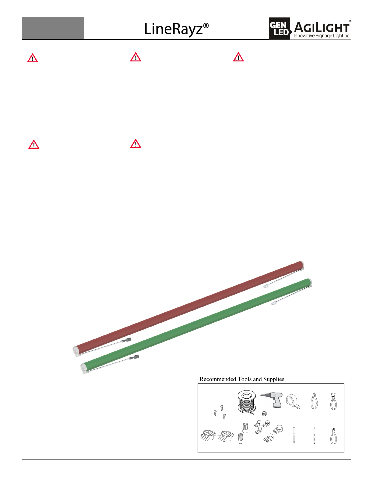
Recommended Tools and Supplies

Installation Guide
AgiLight Inc. 1074 Arion Circle, Suite 116, San Antonio, TX 78216, United States of America, +1.866.482.0203 www.AgiLight.com
Page 2 of 4 www.GENLEDBrands.com
© 2019 AgiLight Inc. 2019 All rights reserved.
Product Specifications subject to change without notice.
ING-01134 11-2019
Installation Instructions:
Attaching to structure:
1. Use a chalk or laser line to create a straight line where you want to mount the center line of the tubes.
2. Attach Mounting Brackets to the wall using screws, M3.5 or #8 pan head screws, per Table 1. The center of
the first mounting bracket should be 40mm (1.5in) from where you want the end of the first tube. Leave
roughly 575mm (22 5/8 in) between clips on the tube. Please note the tubes can increase in length in hot
weather so leave 16mm between the ends of tubes or any other structure.
Table 1
3. Press tube into clips making sure the alignment feature on the back of the tube fits into the pocket in the
clips.
4. When positioning the tubes be sure to leave at least a 16mm gap between the ends to allow for expansion of
the tubes on hot days.
Product First Bracket Brackets
per Tube
Last Bracket on
First tube
Last Bracket to Next
Tube First Bracket
2.4m 40mm / 1.5in 52340mm / 92.13 in 95mm / 3.75in
1.2m 40mm / 1.5in 31162mm / 45.75 in 95mm / 3.75in
0.7m 40mm / 1.5in 2635 / 25 in 95mm / 3.75in
5C 40mm / 1.5in 240mm/1.5in from end 95mm / 3.75in
Last Bracket
Next Bracket
M3.5 or #8 Panhead screw
Clip pocket Alignment feature

Installation Guide
AgiLight Inc. 1074 Arion Circle, Suite 116, San Antonio, TX 78216, United States of America, +1.866.482.0203 www.AgiLight.com
Page 3 of 4 www.GENLEDBrands.com
© 2019 AgiLight Inc. 2019 All rights reserved.
Product Specifications subject to change without notice.
ING-01134 11-2019
AC-LNRZ-EN-D-PLG-A
Last tube in string
24V DC
5. Make the electrical connections between tubes as
you go. Wires can be folded under the tube and held
in place by the mounting clips. Tuck the wires into
the clip before pressing the tube into place.
Power Supply / Electrical Connection
After mounting the tubes in their proper location, you will need to make an electrical connection to a 24VDC
power supply.
1. Connect the Power Supply Pig Tail, AC-LNRZ-02-2-PSHR-A
to the power supply. Connect two if you are placing
the power supply in the middle of a run. If installing
outdoors make sure to use water tight connectors.
2. Connect the power supply pig tail to the first tube in the string.
3. Use an end plug, AC-LNRZ-EN-D-PLG-A to seal the last connector
in the string if you do not end on a Cut Tube.
4. Connect power supply to line source
AC-LNRZ-02-2-PSHR-A
AC-LNRZ-02-2-PSHR-A
First tube in string
AC-LNRZ-02-2-PSHR-A

Installation Guide
AgiLight Inc. 1074 Arion Circle, Suite 116, San Antonio, TX 78216, United States of America, +1.866.482.0203 www.AgiLight.com
Page 4 of 4 www.GENLEDBrands.com
© 2019 AgiLight Inc. 2019 All rights reserved.
Product Specifications subject to change without notice.
ING-01134 11-2019
Field Cut Tube (LB-LRNZ-XXX-5C-Y) install:
Make sure there is no rain or sharp temperature changes scheduled for the next 24 hours before installing the
cut tube outside.
1. Measure the length of tube needed to complete the run, remembering to reduce the length to allow for a
16mm gap. The end with the connector will be connecting to the run. The rest of the cut off tube is scrap and
can be discarded, follow the correct waste laws for your local area.
2. Cut a Field Cut Tube at the closest cut mark. Make sure the cut face is perpendicular to the axis of the tube
and smooth. A rough or angled cut can cause the cap to not fit or seal the tube.
3. Use a clean lint free rag to remove any dust or debris from the cutting
process. Any oil or contamination will result in a weak joint seal and
allow water to enter the tube.
4. Apply a thin bead of SciGrip 16 to the cut end of the tube.
5. Apply SciGrip 16 to the inner perimeter of the included end cap. Make
sure to get a good bead of glue in the hatched area of the image.
6. Slowly press the cap onto the tube and hold with a piece of tape for at least
15 minutes to allow the glue to set. After the glue has set you can remove the
tape and install the tube.
7. Snap the tube into the mounting clips just like you would for a full length tube. Make sure there are two
clips to keep the tube aligned after installation.
Cut flat, clean and
apply a small
amount of Sci Grip
Problem Possible Cause
All tubes are OFF or some of the tubes are
not illuminated. 1. Power supply may not be loaded properly with tubes.
2. Wrong Power Supply. Must be constant voltage.
3. Bad, loose or improper connections.
Entire section does not light or lights
intermittently. 1. Bad, loose, or improper connections.
2. Power supplies are spaced too close together; overheating.
Note: Spacings between LED power supplies shall be at least 1 inch (25.4mm) from end to end, and 4 inches
(101.6mm) from side to side.
Tubes flicker or appear dim. 1. Power supply may not be properly loaded with tubes, too many or too few tubes
2. Power supply may be damaged or defective.
3. Power supply may not be wired correctly. Check AC input wiring. (Green to Ground, Black or Brown to Line, and
White or Blue to Neutral).
Other Agilight Lighting Equipment manuals
Popular Lighting Equipment manuals by other brands

American DJ
American DJ Roto Balls Tri LED User instructions

Castaldi Lighting
Castaldi Lighting D51/0 thor Installation and maintenance sheet

SCHOTT
SCHOTT EasyLED user manual

Chauvet Professional
Chauvet Professional COLORado 1QS Quick reference guide

American DJ
American DJ Dynasty Ray User instruction

Namron
Namron PANELOVN ZIGBEE 400W instruction manual