8
OPERATION
CAUTION: VEHICLE BRAKING AND
STABILITY MAY BE AFFECTED WITH
THE ADDITION OF AN ACCESSORY
OR AN ATTACHMENT. BE AWARE OF
CHANGING CONDITIONS ON SLOPES.
1. Re er to the vehicle owners manual or instructions
on sa e operation on slopes.
2. Use the slope guide provided on page 9 o this
manual to determine i slope angle is too steep or
sa e operation.
3. For best handling and traction, distribute the weight
o the load evenly in the cart.
4. Always test to make sure your tractor has adequate
towing and braking capabilities whenever hauling a
substantial amount o weight in your cart. Use extra
caution when operating on slopes.
5. To dump material rom the cart, remove the tailgate
by li ting it straight up and out rom between the
guides. Release the spring latch on the tongue by
pulling the latch lock handle orward, away rom the
cart. The cart bed will then tilt backwards to empty its
contents. A ter emptying, pull the ront o the bed
down toward the cart tongue until the latch snaps into
place. Replace the tailgate i desired.
6. The maximum towing speed or this cart is 20 m.p.h.
NOTE
DO NOT EXCEED WEIGHT CAPACITY OF CART
(See the speci ications on this page or each model)
One cubic foot of dirt weighs approximately 150 lbs.
CAUTION: TO AVOID POSSIBLE
INJURY, BEFORE RELEASING THE
LATCH BE SURE THAT NO ONE IS
NEAR THE CART.
MAINTENANCE
1. At the beginning o each season, using a light
machine oil, lubricate the latch, the latch pivot
bolt, and the area o the axle where the draw bar
tongue pivots .
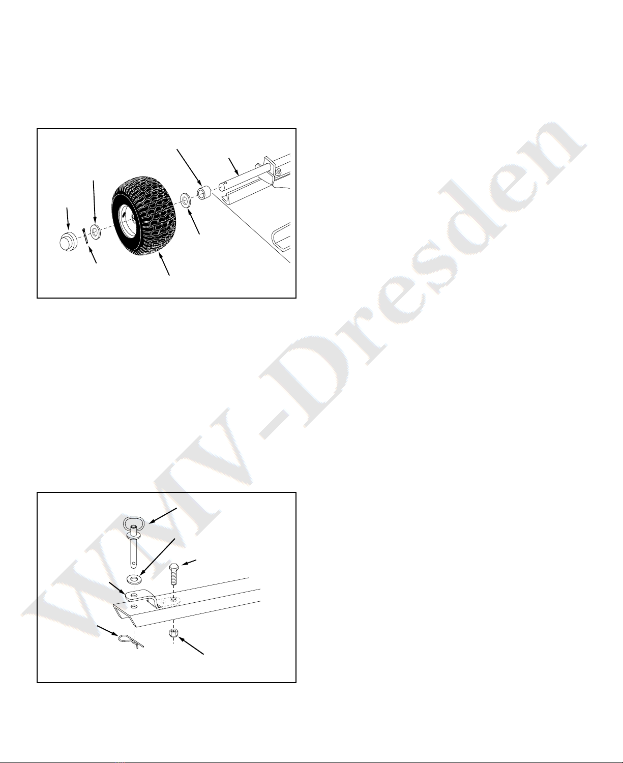
2. At the beginning o each season, grease the wheel
bearings. Apply grease through the grease zerk in
the wheel hub.
3. Check periodically or loose bolts.
4. Keep tires illed. Do not exceed maximum tire
pressure o 10 Lbs.
SPECIFICATIONS FOR "ATV" DUMP CART
MODEL 45-02173 & 190-521A-100
Tires: 18.0" x 9.5" Pneumatic
Axle: 1.0" Dia. Steel
Capacity: Up to 1700 Lbs. Max.
Approx. Sh. Wt.
195 Lbs.