Agri-Fab 45-0491 User manual

Model No.
45-0491
OWNERS
MANUAL
PRINTED IN U.S.A. FORM NO. 42432 (05/31/13)
CAUTION:
Read Rules for
Safe Operation
and Instructions
Carefully
• Safety
• Assembly
• Operation
• Maintenance
• Parts
50" SNOW THROWER
the fastest way to purchase parts
www.speedepart.com
™
Want more information or assembly tips?
Scan with free ShowUHow Mobile App
available at iTunes Store or Google Play.

2
TABLE OF CONTENTS
SERVICE AND ADJUSTMENTS...................................20
STORAGE .....................................................................21
TROUBLESHOOTING...................................................21
REPAIR PARTS ILLUSTRATION........................22,24,26
REPAIR PARTS LIST...........................................23,25,26
SLOPE GUIDE ..............................................................27
PARTS ORDERING/SERVICE ...................BACK COVER
ACCESSORIES...............................................................2
SAFETY RULES..............................................................3
FULL SIZE HARDWARE CHART.................................4,5
CARTON CONTENTS.....................................................6
ASSEMBLY......................................................................7
OPERATION..................................................................18
MAINTENANCE ............................................................19
IMPORTANT:
Rear wheel weights and tire chains are required to provide extra traction and
stability when using this snow thrower attachment. These items are available
where you purchased your tractor.
WHEEL WEIGHTS TIRE CHAINS

3
SAFETY
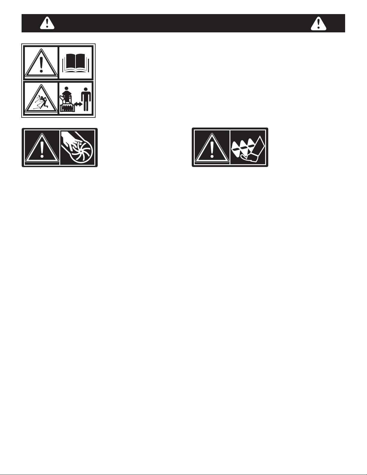
Read and understand the operating instructions before using.
Keep the area of operation clear of all persons, especially small children and pets.
Thoroughly inspect the area to be cleared and remove all door mats, sleds, boards,
wires and other foreign objects. Use extreme caution when operating on or crossing
gravel surfaces. Never direct discharge at bystanders or allow anyone in front of the
snow thrower.
Do not place hands near rotating parts. Keep clear of the
discharge opening at all times.
Do not place feet near rotating parts.
• Never allow children to operate the equipment.
• Never allow adults to operate the equipment without
proper instruction.
• Disengage all clutches and shift into neutral before
starting engine.
• Do not operate equipment without wearing adequate
winter outer garments.
• Wear substantial footwear which will protect feet and
improve footing on slippery surfaces.
• Check fuel before starting the engine. Do not remove
the fuel cap or ll the fuel tank while the engine
is running or hot. Do not ll the fuel tank indoors.
Gasoline is an extremely ammable fuel.
• Make sure the snow thrower height is adjusted to
clear the type surface it will be used on.
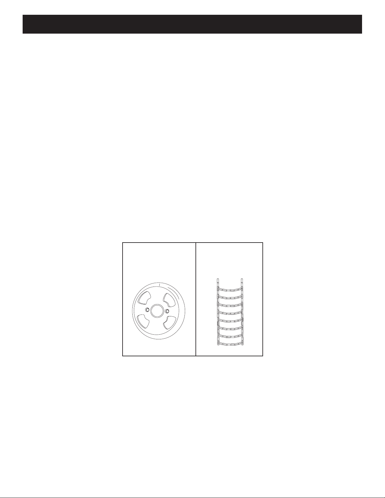
• Do not use the snow thrower without wheel weights
attached to the tractor.
• Never make any adjustments while the engine is
running.
• Always wear safety glasses or eye shield during
operation or while performing adjustment or repair.
• Do not place hands or feet near rotating parts. Keep
clear of the discharge opening at all times.
• Do not carry passengers.
• After striking a foreign object, stop the engine, remove
the wire from the spark plug and then thoroughly
inspect the snow thrower for damage. Repair any
damage before restarting and operating the snow
thrower.
• If the snow thrower starts to vibrate abnormally, stop
the engine immediately and check for the cause.
Vibration is generally a warning of trouble.
• Stop the engine whenever you leave the operating
position, before unclogging the snow thrower or
making any adjustments or inspections.
• Take all possible precautions when leaving the unit
unattended. Disengage the attachment clutch lever or
switch, lower the snow thrower, shift into neutral, set
the parking brake, stop the engine and remove the key.
• When cleaning, repairing or inspecting, make certain
all moving parts have stopped. Disconnect the spark
plug wire and keep it away from the plug to prevent
accidental starting.
• Do not run engine indoors except when transporting
the snow thrower in or out of the building. Open the
outside doors. Exhaust fumes are dangerous.
• Do not clear snow across the face of slopes. Exercise
extreme caution when changing direction on slopes.
Do not attempt to clear steep slopes. Refer to the
slope guide on page 35 of this manual.
• Never operate the snow thrower without guards,
plates or other safety protection devices in place.
• Never operate the snow thrower near glass
enclosures, automobiles, window wells, drop offs
etc. without proper adjustment of the snow thrower
discharge angle.
• Never run the snow thrower into snow at high speeds.
• Do not overload the snow thrower capacity by
attempting to clear snow at too fast a rate.
• Never operate the snow thrower at high transport
speed on slippery surfaces. Look behind and use care
when backing up.
• Watch for trafc and stay alert when crossing or
operating near roadways.
• Disengage power to the snow thrower when
transporting or when not in use.
• Use only attachments and accessories approved by
the manufacturer of the snow thrower (such as wheel
weights, counter weights, cabs etc.)
• Never operate the snow thrower without good visibility.
184045
199683199682

4
HARDWARE PACKAGE CONTENTS
SHOWN ACTUAL SIZE
43063
R19171616
ABCD
I JH LK M
N O
F G
V
P
TU
S
R
Q
W
46938
710-0890A
43003
43070
43088 43081
47630
44695 43082 47810 47572
R19172410
44215
43682
44326
43080
47598
43350
48106
49933
X
43661
E
43182
ATTENTION: The hardware bags may contain some bolts and nuts which do not appear on this page or the following
page. Those bolts and nuts will not be needed for the assembly of your snow thrower.

5
REF. QTY. DESCRIPTION
A 1 Hex Bolt, 3/8" x 3-1/4"
B 4 Hex Bolt, 5/16" x 1"
C 4 Hex Bolt, 5/16" x 3/4"
D 6 Hex Bolt, 1/4" x 1"
E 2 Hex Bolt, 5/16" x 3/4" (Thread Forming)
F 2 Shear Bolt (spare parts)
G 2 Shoulder Bolt, Hex Head
H 2 Shoulder Bolt, Round Head
I 6 Carriage Bolt, 3/8" x 1"
J 2 Carriage Bolt, 5/16" x 1-3/4"
K 2 Carriage Bolt , 5/16" x 1-1/4"
L 4 Carriage Bolt, 5/16" x 1"
M 1 Carriage Bolt, 5/16" x 3/4"
N 1 Washer, 1/2" x 1"
O 7 Washer, 1/4"
P 19 Washer, 5/16" (Extra washers included)
Q 3 Washer, 3/8" Standard
R 4 Washer, 1/2" x 1-1/2"
S 2 Bowed Washer
REF. QTY. DESCRIPTION
T 1 Lock Washer, 3/8"
U 2 Hex Lock Nut, 3/8"
V 19 Nylock Nut, 5/16" (2 spare parts)
W 10 Flanged Nut, 3/8"
X 6 Flanged Nut, 1/4"
Y 1 Spring
Z 3 Chute Keeper
AA 2 Hairpin Cotter, 5/64"
BB 1 Hairpin Cotter, 3/32"
CC 6 Hairpin Cotter
DD 2 Lock Pin
EE 2 Clevis Pin, 1/2" x 7/8"
FF 1 Plastic Cap
GG 1 Spacer, 1/4"
HH 1 Spacer, 3/8"
II 2 Chain, Tensioning
JJ 2 Tail Reector
KK 8 Nylon Tie
LL 1 Cable Clip
IMPORTANT: Not all items supplied in the hardware bags will be needed for your particular tractor. Unneeded items
may be discarded after you have completed assembly and checked operation of unit. DO NOT DISCARD the two spare
shear bolts (F) and 5/16" nylock nuts (V). Refer to the Service and Adjustments section on page 20.
JJ
NOT SHOWN ACTUAL SIZE
II
EE
KK LL
GG
YZ
46959
AA
731-0851A
BB
47134
DD
43343
CC
43055
43038 1643-60711-0332
46963
726-0178
47788 HA23761
23727
FF
HH
25780

6
CARTON CONTENTS
1. Housing Assembly
2. Chute Crank Rod Assembly
3. Support Tube, Crank Rod
4. Winch Assembly
5. Anti-rotation Bracket.
6. Front Pulley Frame Bracket (2)
7. Rear Pulley Frame Bracket (2)
8. V-Belt, Drive 56" (#48138)
9. V-Belt, Drive 55" (#46989)
10. V-Belt, Auger (Attached to Housing Assembly)
11. Clutch Idler Assembly
12. Cable Bracket
13. L.H. Hanger Bracket
14. R.H. Hanger Bracket
15. Pulley
16. Chute and Control Cable Assembly
17. Right Hand Side Plate
18. Left Hand Side Plate
19. Switch Mounting Assembly
20. Wire Harness
46989
48138
47846
19
18
5
14
3
12
13
16
10
8
1
11
2
17
9
25678 25679
24394
65450
65367
25728
24558
7
6
27016
48883
15
4
67714 42554
20

7
TOOLS REQUIRED FOR ASSEMBLY
(2) 7/16" Wrenches
(2) 1/2" Wrenches
(2) 9/16" Wrenches
(2) 3/4" Wrenches
(1) Screw Driver
(1) Knife
ASSEMBLY
• Remove all loose parts, parts bags and hardware
bags from the carton. Lay out and identify parts and
hardware using the illustrations on pages 4, 5 and 6.
IMPORTANT: Not all items supplied in the hardware
bag will be needed for your particular tractor. Unneeded
items may be discarded after you have completed
assembly and checked operation of unit. DO NOT
DISCARD the two spare shear bolts and 5/16" nylock
nuts. Refer to the Service and Adjustments section on
page 20.
REMOVAL OF PARTS FROM CARTON
TRACTOR PREPARATION
Before performing these instructions, refer to the Service
and Adjustments section of your tractor owner's manual
for specic safety instructions.
• Allow engine, mufer and exhaust deector to cool
before beginning.
• Remove any front or rear attachment which is
mounted to your tractor.
•Remove the mower deck. Refer to your tractor owner's
manual for removal instructions. Mark all loose parts
and save for reassembly.
• Remove the tractor hood. Refer to your tractor owner's
manual for removal instructions.
IMPORTANT: Right hand (R.H.) and left hand (L.H.) side
of the tractor are determined from the operators position
while seated on the tractor.
CAUTION: Before starting to assemble the
snow thrower, remove the spark plug wire(s),
set the parking brake and remove the key from
the tractor ignition.
STEP 1: (SEE FIGURE 1)
• Align the Winch and Bracket Assembly with the front
of the tractor frame and install two 3/8" x 1" carriage
bolts through each side of the tractor frame and the
bracket. Do not install any nuts yet.
FIGURE 1 RIGHT SIDE VIEW
3/8" x 1"
CARRIAGE BOLTS (4)
ATTACHING PARTS TO TRACTOR FRAME
FIGURE 2 RIGHT SIDE VIEW
1/2" x 1-1/2"
WASHER
3/8" x 1"
CARRIAGE
BOLT
5/16" x 1"
CARRIAGE
BOLT
STEP 2: (SEE FIGURE 2)
• On each side of the tractor frame insert a 3/8" x 1"
carriage bolt and a 5/16" x 1" carriage bolt through the
holes shown.
• Install a 1/2" x 1-1/2" washer onto each bolt unless
there is an engine mounting plate present (depicted
with dotted lines). If there is a plate, do not install a
washer on the 3/8" bolt inserted through the plate.
CAUTION: Do not begin assembling until
the tractor engine, mufer and exhaust
deector have been allowed to cool off.

8
STEP 4: (SEE FIGURE 4)
•Place the R.H. Side Plate onto the bolts you inserted
into the tractor frame. Install three 3/8" anged lock
nuts and one 5/16" nylock nut onto the bolts. Tighten.
•Repeat for the L.H. Side Plate.
HINT: To help prevent the carriage bolts from spinning,
push against the head of the bolt while tightening to keep
the square neck of the bolt seated in the square hole.
3/8" FLANGED
LOCK NUT
5/16" NYLOCK
NUT
FIGURE 4 RIGHT SIDE VIEW
STEP 3: (SEE FIGURE 3)
•Install a hex head shoulder bolt, a 3/8" washer and a
3/8" anged lock nut in the R.H. and L.H. Side Plates.
FIGURE 3 RIGHT SIDE VIEW
3/8" WASHER
SHOULDER
BOLT
3/8" FLANGED
NUT
R.H. SIDE PLATE
LH. SIDE PLATE
STEP 6: (SEE FIGURE 6)
HINT: Do not completely tighten the plastic ties until so
instructed in step 7.
• Position the wire harness' black relay box against the
front of the battery tray on the right hand side. Attach
it to the slot in the top of the battery tray using a
plastic tie.
• Route the end of the wire harness with the green and
black wires around behind the tractor's wiring and
then forward along the right side of the tractor.
• Loosely attach the wire harness to rear of the right
hand side plate installed in step 4, and to the right
front corner of the tractor frame using two plastic ties.
• Route the other end of the wire harness with the
brown and black wires around behind the battery
cable on the left side of the battery and then along the
left side of the tractor.
• Loosely attach the wire harness to the hole at the
bottom left corner of the lower dash using a plastic tie.
• Loosely attach the wire harness to the rear of the left
hand side plate installed in step 4, and to the left front
corner of the tractor frame, using two plastic ties.
STEP 5: (SEE FIGURE 5)
• Remove the two screws in the right side of the plastic
dash housing.
• Install the cable clip onto the rocker switch wiring.
Attach the switch mounting assembly and clip to the
side of the plastic dash housing, using the two screws.
FIGURE 5 RIGHT SIDE VIEW
SWITCH
ASSEMBLY
ATTACH RELAY
BOX TO SLOT
ATTACH WIRE
HARNESS HERE
CABLE CLIP
ORIGINAL
SCREWS
CONNECTING THE RELAY BOX
STEP 6: (SEE FIGURE 5)
FRONT MOUNTED BATTERY ONLY
• Position the wire harness relay box against the front of
the battery tray on the right hand side. Attach it to the
slot in the top of the battery tray using a plastic tie.
• Connect the long black wire on the wire harness to
the negative post on the battery.
• Connect the red wire (with circuit breaker) to the
positive post on the battery.

9
INSTALL HANGER BRACKETS AND SHOULDER
BOLTS TO OUTSIDE OF FRAME
STEP 9: (SEE FIGURE 7)
•Remove the bolt, if present, in the hole directly behind
the brake rod on the left side of the tractor frame.
• Attach the L.H. Hanger Bracket (tube facing out) to the
hole using a 5/16" x 3/4" self threading bolt.
• Install a round head shoulder bolt into the hole that is
9-1/2" to the rear of the bolt you just installed. Secure
it with a 3/8" ange nut on the inside of the frame.
FIGURE 7 LEFT SIDE VIEW
5/16" x 3/4" SELF
THREADING BOLT
L.H. HANGER
BRACKET
BRAKE ROD
3/8" FLANGED
NUT
SHOULDER
BOLT
5/16" x 3/4" SELF
THREADING BOLT
R.H. HANGER
BRACKET
RIGHT END OF
BRAKE ROD
3/8" FLANGED
NUT
SHOULDER
BOLT
STEP 10: (SEE FIGURE 8)
•Remove the bracket, if present, from the hole directly
behind the end of the brake rod on the right side of
the tractor frame. Store the bracket and bolt.
• Attach the R.H. Hanger Bracket to the hole using a
5/16" x 3/4" self threading bolt.
• Install a round head shoulder bolt into the hole that is
9-1/2" to the rear of the bolt you just installed. Secure
it with a 3/8" ange nut on the inside of the frame.
FIGURE 8 RIGHT SIDE VIEW
BLACK WIRE
BROWN WIRE
NUT
NUT
WASHER
WASHER
WASHER
WASHER
FIGURE 6 RIGHT SIDE VIEW
INSTALLING THE WIRE HARNESS
STEP 8:
• Connect the three wires of the switch mounting
assembly to the wires with mating connectors from
the wire harness, joining together like colored wires.
• Route the end of the wire harness with the green and
black wires around behind the tractor's wiring and
then forward along the right side of the tractor.
• Route the other end of the wire harness around to the
left side of the tractor.
• Loosely attach the wire harness to rear of each side
plate installed in step 4, and to the front corners of the
tractor frame using two plastic ties per side.
• Connect the wire harness to the winch motor using
the pre-assembled nut and washers. Place the brown
wire on the top terminal and the black wire on the
bottom terminal. See gure 6.
• Tighten the plastic ties.
STEP 7:
REAR MOUNTED BATTERY ONLY
• Mount the wire harness relay box in front of the
solenoid on the right hand side of the gas tank,
attaching it with a plastic tie.
• Attach the long black wire of the wire harness under
the head of the screw that fastens down the right
hand side of the gas tank.
• Attach the red wire (with circuit breaker) to the rear
solenoid terminal where the battery cable is attached.
• Connect the short red, black and green wires to the
three wires of the switch mounting assembly, joining
together like colored wires.

10
STEP 12: (SEE FIGURE 10)
• Attach the pulley (long end of hub facing down) and
the 3/8" spacer to the clutch/idler assembly. Use
a 3/8" x 3-1/4" hex bolt, a 3/8" washer, a 3/8" lock
washer and a 3/8" hex lock nut.
• Insert a tensioning chain through the hole shown and
attach the end link to the spring on the lower idler arm.
FIGURE 10
FIGURE 9
STEP 11: (SEE FIGURE 9)
• Attach the cable bracket to the double hole in the
clutch/idler assembly as shown, using a 5/16" x 3/4"
carriage bolt and a 5/16" nylock nut. Place the bolt in
the front hole of the bracket and in the end of the hole
closest to the pulley. Do not tighten yet.
THIS SECTION IS FOR TRACTORS WITH A
MANUAL ATTACHMENT CLUTCH
If your tractor has an electric attachment clutch go to
step 18 on page 12.
FIGURE 12
HEX BOLTS
(#48138)
DRIVE BELT
FLAT IDLER
PULLEYS
STOP
Did you select the correct drive belt for your
tractor? Using the wrong length belt may
cause premature bearing or belt failure.
STEP 14: (SEE FIGURE 12)
• Two different length drive belts are included with your
snow thrower. Use the longer, 56" drive belt (#48138)
on tractors with manual attachment clutches.
• Slightly loosen the hex bolt next to the at idler pulley.
Install the drive belt down between the hex bolt and the
at idler pulley with the at side of the belt against the
pulley. Retighten the hex bolt.
• Loop the belt around the large V-pulley, placing it
between the V-pulley and the hex bolt next to the pulley.
Place the belt to the inside of the other at idler pulley.
5/16" x 1"
HEX BOLT
5/16" x 3/4"
HEX BOLT 5/16"
NYLOCK
NUT
5/16" WASHER
(2) 5/16"
WASHERS
FIGURE 11
STEP 13: (SEE FIGURE 11)
• Attach each rear pulley frame bracket to the inside of
the clutch/idler assembly using two 5/16" x 3/4" hex
bolts, 5/16" washers and 5/16" nylock nuts.
• Attach each front pulley frame bracket to the inside
of the clutch/idler assembly using two 5/16" x 1" hex
bolts, four 5/16" washers and two 5/16" nylock nuts.
3/8" SPACER
PULLEY
3/8" LOCKWASHER
3/8" HEX LOCK NUT 3/8"
WASHER
LONG END
OF HUB
3/8" x 3-1/4"
HEX BOLT
TENSIONING CHAIN
CABLE
BRACKET
5/16" x 3/4"
CARRIAGE BOLT
5/16" NYLOCK
NUT

11
ATTACH CLUTCH IDLER ASSEMBLY TO TRACTOR
STEP 16: (SEE FIGURE 14)
• Attach the clutch/idler assembly to the tractor frame.
Hook the notched rear pulley frame brackets onto the
two shoulder bolts assembled to the outside of the
tractor frame. Lift the front of the assembly and attach
it to the R.H. and L.H. hanger brackets using two pivot
lock pins and 1/8" hairpin cotters.
• Loosely attach the mower clutch cable to the left side
of the tractor frame with a nylon tie. Do not pull the
nylon tie completely tight. The cable may need to be
removed from the nylon tie when using the mower
deck.
PIVOT LOCK PIN
(use this hole)
SHOULDER
BOLT
L.H. HANGER
BRACKET
1/8" HAIRPIN
COTTER
NYLON TIE
MOWER
CLUTCH
CABLE
FIGURE 14 VIEWED FROM LEFT SIDE
FIGURE 15 VIEWED FROM UNDERNEATH
FIGURE 13
STEP 15: (SEE FIGURE 13)
• Find the cable clip that is attached to the left side
of the tractor frame underneath the footrest. Open
the clip and remove the mower clutch cable. Do not
remove the clip from the tractor frame. The cable
reattaches to the clip when using the mower deck.
• Move the attachment clutch lever on the dash panel to
the disengaged position.
• Place the clutch/idler assembly on the oor on the left
side of the tractor.
• Attach the tractor's mower clutch cable to the cable
bracket on the clutch/idler assembly. Secure the cable
housing guide (groove down) to the cable bracket
using the original collar and retainer spring.
• Place a 1/4" spacer on the welded pin on the idler
arm. Hook the end of the clutch cable spring over the
pin and secure it with a 1/4" washer and a 5/64" hair
cotter pin.
• Align cable bracket with welded pin and tighten the
nut assembled in step 11.
5/64" HAIR
COTTER PIN
1/4" WASHER
1/4" SPACER
TRACTOR'S
CLUTCH CABLE
CABLE
BRACKET
ENGINE
PULLEY
HEX BOLT
FLAT IDLER
PULLEY
ENGINE
PULLEY
BELT KEEPERS
STEP 17: (SEE FIGURE 15)
• Assemble the drive belt onto the engine pulley, routing
it through the engine pulley belt keepers.
HINT: You may need to remove the belt from the large
pulley on the clutch/idler assembly in order to assemble
it onto the engine pulley. When re-assembling the belt
onto the large pulley, be sure the belt is between the large
pulley and the hex bolt next to it.
• Go to step 24 on page 14.
LEFT SIDE
OF TRACTOR

12
FIGURE 18
TABLE 1
5/16" x 1" HEX BOLT
5/16" x 3/4"
HEX BOLT
5/16" NYLOCK NUT
5/16" WASHER
5/16"
NYLOCK NUT
(2) 5/16" WASHERS
STEP 20: (SEE FIGURE 18)
• Attach each rear pulley frame bracket to the inside of
the clutch/idler assembly using two 5/16" x 3/4" hex
bolts, 5/16" washers and 5/16" nylock nuts.
• Attach each front pulley frame bracket to the inside
of the clutch/idler assembly using two 5/16" x 1" hex
bolts, four 5/16" washers and two 5/16" nylock nuts.
THIS SECTION IS FOR TRACTORS WITH AN
ELECTRIC ATTACHMENT CLUTCH
3/8" HEX
LOCK NUT
SPRING
ATTACH
SPRING
HERE
STEP 18: (SEE FIGURE 16)
• Turn the clutch idler assembly upside down.
• Hook the spring onto the end of the bolt that extends
through the nut on the bottom of the upper idler
arm. Install a 3/8" hex lock nut onto the bolt, leaving
enough space for the spring to pivot.
FIGURE 16 BOTTOM VIEW
FIGURE 17
STEP 19: (SEE FIGURE 17)
• Insert tensioning chains through the holes shown and
attach to the springs on the upper and lower idler arms.
• Install a 3/32" hairpin cotter in the chain attached to
the upper idler arm, placing it in the fth link from the
spring.
TENSIONING CHAIN (lower idler arm)
TENSIONING CHAIN (upper idler arm)
3/32" HAIRPIN
COTTER IN
5th LINK
STEP 21: (SEE FIGURE 19)
• Two different length drive belts are included with your
snow thrower. Use the shorter, 55" drive belt (#46989)
on tractors with electric clutches.
• Turn the clutch/idler assembly right side up.
• Slightly loosen the hex bolt next to the at idler pulley.
Install the drive belt between the hex bolt and the at
idler pulley. Retighten the hex bolt.
• Loop the belt around the large V-pulley, placing it
between the V-pulley and the hex bolt next to the pulley.
FIGURE 19
STOP
Did you choose the correct drive belt for
your tractor? Using the wrong length belt
may cause premature bearing or belt failure.
(#46989)
DRIVE BELT
FLAT IDLER
PULLEY
HEX BOLTS

13
STEP 22: (SEE FIGURE 20)
• Attach the clutch/idler assembly to the tractor frame.
Hook the notched rear pulley frame brackets onto the
two shoulder bolts assembled to the outside of the
tractor frame. Lift the front of the assembly and attach
it to the R.H. and L.H. hanger brackets using two pivot
lock pins and 1/8" hairpin cotters.
PIVOT LOCK PIN
(use second hole)
SHOULDER
BOLT
1/8" HAIRPIN
COTTER
L.H. HANGER
BRACKET
FIGURE 20 VIEWED FROM LEFT SIDE
STEP 23: (SEE FIGURE 21)
• Assemble the drive belt onto the engine pulley. You
may need to remove the belt from the large pulley on
the clutch/idler assembly in order to assemble it onto
the engine pulley. When re-assembling the belt onto
the large pulley, be sure the belt is between the large
pulley and the hex bolt next to it.
• Place tension on the belt by pulling the left side
tensioning chain out as far as the 3/32" hairpin cotter
that was installed in the chain in step 17 will allow.
Secure the chain in this position by inserting a 1/8"
hairpin cotter through the chain.
NOTE; To prevent the chain from dragging on the
ground, loop the end of the chain though the pivot lock
pin. Refer to gure 31 on page 16.
• Go to step 24 on page 14.
FIGURE 21 VIEWED FROM UNDERNEATH
1/8"
HAIRPIN
COTTER
ENGINE
PULLEY
HEX BOLTS
FLAT IDLER
PULLEY
TENSIONING
CHAIN
LEFT SIDE
OF TRACTOR

14
STEP 24: (SEE FIGURE 22)
• Remove the nylon tie which fastens the chute crank
rod to the crank rod support tube.
• Assemble the crank rod support tube to the bracket
on the left side of the discharge housing using two
5/16" x 1-1/4" carriage bolts, and 5/16" Nylock nuts.
FIGURE 23 LEFT SIDE VIEW
CHUTE CRANK ROD
CRANK SUPPORT TUBE
TILT CONTROL HANDLE
5/16" x 1-3/4"
CARRIAGE BOLT
BOWED WASHER
5/16" NYLOCK NUT
TILT
CONTROL
ASSEMBLY
STEP 25: (SEE FIGURE 23)
• Attach the chute tilt control assembly to the top side
of the crank support tube using two 5/16" x 1-3/4"
carriage bolts, bowed washers and 5/16" Nylock nuts.
5/16" NYLOCK NUT
5/16" x 1-1/4"
CARRIAGE BOLT
CRANK ROD
SUPPORT TUBE
DISCHARGE
HOUSING
FIGURE 22 LEFT SIDE VIEW
5/16" NYLOCK NUT
CHUTE CRANK
BRACKET
5/16" WASHER
CHUTE
CRANK
ROD
ROD
SUPPORT
BRACKET
5/16" x 1"
CARRIAGE BOLT
SPIRAL
FIGURE 24 LEFT SIDE VIEW
STEP 26: (SEE FIGURE 24)
• Attach the chute crank rod assembly brackets to
the plastic bracket on the left side of the discharge
housing. Align the chute crank bracket beneath the
rod support bracket and assemble both to the plastic
bracket using two 5/16" x 1" carriage bolts, 5/16"
washers and 5/16" Nylock nuts. Do not tighten yet.

15
FIGURE 25 RIGHT SIDE VIEW
CHUTE KEEPER
ANTI-ROTATION
BRACKET
1/4" FLANGED
LOCK NUT
1/4" FLAT
WASHER
1/4" x 1"
HEX BOLT
PLASTIC CAP
GREASED
SURFACE
FLANGE
STEP 27: (SEE FIGURE 25)
• Coat the top of the ring around the discharge opening
with general purpose grease.
• Place the discharge chute (facing forward) onto the
ring. Place the anti-rotation bracket on top of the chute
ange, aligning it with the holes on the right hand side
of the ange. Attach the three chute keepers (right
side up as shown) to the bottom of the ange using
six 1/4" x 1" hex bolts, 1/4" at washers and 1/4"
anged lock nuts. Tighten carefully so that the nuts
are snug but do not dig into the plastic chute keepers.
• Place the plastic cap onto the short end of the anti-
rotation bracket.
• Position the crank rod spiral (see gure 24 on page
14) so that it does not rub against the bottoms of the
notches in the chute ange. Tighten the nuts.
• Check if the crank rod rotates the chute freely. If not,
loosen by 1/4 turn each of the six hex bolts holding
the chute keepers to the chute ange.
• Secure the control cables to the crank rod support
tube using two nylon ties.
ATTACHING SNOW THROWER TO TRACTOR
FIGURE 26 RIGHT SIDE VIEW
STEP 28: (SEE FIGURE 26)
• Place the snow thrower on a at, level surface.
• Extend the auger belt out behind the snow thrower,
leaving the belt assembled to the snow thrower pulleys.
• Roll the tractor up behind the snow thrower, centering
it between the snow thrower's mounting plates.
• Lift up on the crank rod support tube to raise the
rear of the snow thrower and align the notches in the
mounting plates align with the shoulder bolts in the
tractor's side plates. Roll the tractor forward, guiding
the shoulder bolts into the notches.
• Install the two 1/2" x 7/8" clevis pins and 1/8" hairpin
cotters to secure the snow thrower to the tractor.
1/8" HAIRPIN
COTTER
1/2" x 7/8"
CLEVIS PIN
FIGURE 27 RIGHT SIDE VIEW
STEP 29: (SEE FIGURE 27)
• Connect the terminals of the wire harness attached to
the tractor with the wire terminals of the limit switches
on the snow thrower.
WIRE HARNESS
TERMINALS
LIMIT SWITCH
TERMINALS

16
FIGURE 30 VIEWED FROM UNDERNEATH
INSTALLING THE AUGER BELT
STEP 32: (SEE FIGURE 30)
• Start with the snow thrower lowered to the ground.
• Swing the idler arm over to the L.H. side of the tractor.
• Place the auger belt around the rear V-pulley and
between the two idler arm pulleys. The "V" side of the
belt must be seated in the grooves of the V-pulleys.
HINT: If the belt is too tight to assemble, try temporarily
releasing the spring tension on the upper drive belt and
then turning the rear pulley while rolling the auger belt
onto it. If the belt is still too tight to assemble, try raising
the snow thrower to see if the belt is looser in that position.
BELT ROUTING DIAGRAM
ENGINE PULLEY
STEP 31: (SEE FIGURE 29)
• Check to make sure the auger belt is still properly
seated around the snow thrower's auger pulley and
idler pulleys.
IDLER
PULLEY
AUGER PULLEY TWIST
1/4 TURN
TWIST
1/4 TURN
IDLER
PULLEY
FIGURE 29
FIGURE 28 VIEWED FROM UNDERNEATH
PUSH HERE
1/2" WASHER
5/64" HAIRPIN
COTTER
WINCH CABLE
LIFT STOP
PLATE
LIFT LINK
STEP 30: (SEE FIGURE 28)
• Place the end of the winch cable onto the lift link.
Place a 1/2" washer onto the link and install a 5/64"
hairpin cotter.
HINT: Push on the lift stop plate to rotate the lift link into
better position to install the winch cable.
REAR
PULLEY
AUGER
BELT
IDLER ARM V-PULLEY
IDLER ARM
FLAT PULLEY
LEFT SIDE
OF TRACTOR

17
INSTALLING THE ATTACHMENT PIN
STEP 58: (REFER BACK TO FIGURE 54 ON PAGE 24)
• Lift the front of the snow blower to align the holes in
the mounting plates and the side plates. From the left
side of the tractor insert the attachment pin through
the holes. Secure it with by reinstalling the 1/8" hairpin
cotter.
SETTING THE AUGER BELT TENSION
STEP 33: (SEE FIGURE 31)
• Pull the right side tensioning chain until the end of the
spring is pulled into the hole in the side of the Clutch/
Idler assembly. Install a 1/8" hairpin cotter through
the end of the spring, securing it on the outside of the
Clutch/Idler assembly.
IMPORTANT: For correct belt tension, the 1/8" hairpin
cotter must attach to the end of the spring, not to the
chain.
NOTE; To prevent the chain from dragging on the
ground, loop the end of the chain though the pivot lock
pin. Refer to gure 30 on page 16.
FIGURE 31 VIEWED FROM UNDERNEATH
CHECKLIST
Before you operate your snow thrower, please review
the following checklist to help ensure that you will
obtain the best performance from your snow thrower.
• Make sure all assembly instructions have been
completed with all bolts and nuts properly tightened.
• Make sure the correct drive belt was installed.
• Make sure the drive belt and auger belt are routed
properly around pulleys and inside all belt keepers.
• Check discharge chute for proper rotation.
• Check operation of tilt control for upper chute.
• Verify that the snow thrower raises and lowers
properly.
• Check skid shoe adjustment. (Refer to the Service
and Adjustments section.)
REAR REFLECTORS
ATTACH REFLECTORS TO REAR FENDER
STEP 34: (SEE FIGURE 32)
• If your tractor is not equipped with rear reectors,
assemble the supplied rear reectors to the rear
fender. Place the reectors as close to the bottom of
the fender and as far apart as the shape of the fender
will allow.
FIGURE 32
RIGHT SIDE OF TRACTOR
1/8" HAIRPIN COTTER
IDLER FLAT PULLER
AUGER BELT

18
OPERATION
KNOW YOUR SNOW THROWER
Read this owner's manual and safety rules before operating your snow thrower.
Compare the illustration below with your snow thrower to familiarize yourself with the various controls and their locations.
CHUTE TILT HANDLE Pivots the Upper Chute up or
down to control the angle and distance of discharge.
CRANK ROD Rotates the Lower and Upper Chutes to
control the direction of discharge.
TOGGLE SWITCH Used to raise or lower the snow thrower
to transport or operating position.
UPPER AND LOWER DISCHARGE CHUTE Controls
direction and height of snow discharge.
SCRAPER PLATE Replaceable plate that absorbs
wear and impact from contact with ground.
SKID SHOE Controls amount of clearance between
the scraper plate and the ground.
SPIRAL AUGER, R.H. & L.H. Feed snow to the
impeller fan at the center of the housing.
BEFORE STARTING
• Use the end of assembly checklist to verify that all
instructions have been properly completed.
• Make sure the skid shoes are adjusted to maintain
adequate ground clearance between the snow
thrower and the type of surface to be cleared. (Refer
to the Service and Adjustments section.)
• Make sure the tractor engine has the correct oil
for winter operation (SAE 5W-30). Refer to tractor
owner's manual.
HOW TO START YOUR SNOW THROWER
•The tractor should be sitting with the engine running
at full throttle. Move the attachment clutch to the
engaged position, starting the snow thrower before
the tractor clutch is engaged.
HOW TO STOP YOUR SNOW THROWER
• To stop the snow thrower, disengage the tractor's
attachment clutch lever for manual clutches or the
clutch switch for electric clutches. Refer to your tractor
owner's manual.
CAUTION: Never direct discharge
towards bystanders or windows. Do not
allow anyone in front of unit.
CONTROLLING SNOW DISCHARGE
• To control the direction snow is thrown, the discharge
chute has 180 degrees of rotation. Turn the crank rod
to rotate the chute to the right or the left.
• To control the distance snow is thrown, the upper
section of the discharge chute pivots up and down.
Push forward on the chute tilt handle to pivot the
chute down, decreasing the distance snow is thrown.
Pull back on the handle to pivot the chute up,
increasing the distance snow is thrown.
HOW TO USE YOUR SNOW THROWER
CRANK ROD
CHUTE TILT HANDLE
UPPER CHUTE
LOWER CHUTE
SPIRAL AUGERS, R.H. & L.H.
SKID SHOE
SCRAPER PLATE
TOGGLE SWITCH

19
RAISING AND LOWERING
• Use the toggle switch attached to the side of the
tractor's dash to raise or lower the snow thrower. The
winch motor will shut off when the snow thrower is in
either the up or down position.
CUSTOMER RESPONSIBILITIES
• Read and follow the maintenance schedule and the maintenance procedures listed in this section.
Service Dates
Check for loose fasteners X
Check scraper and shoes for wear X X
Cleaning X
Lubrication Section X
MAINTENANCE SCHEDULE
Fill in dates as you
complete regular service.
Before each use
After each use
Every season
Before storage
LUBRICATION
•Oil all pivot points on the snow thrower.
• Oil the pivot points of the two idler arms on the clutch/
idler assembly.
• Apply penetrating oil to the control cables of the
discharge chute.
• Apply a good grade of spray lubricant to the chute tilt
control assembly.
CAUTION: Do not operate the snow
thrower without rear wheel weights
attached to the tractor to provide extra
traction and stability.
MAINTENANCE
CHECK SCRAPER AND SHOES FOR WEAR
(Refer to gures 33 and 34 on page 20.)
• The scraper plate and skid shoes on the bottom of the
snow thrower are subject to wear. To prevent damage
to the spiral auger housing, replace plate and shoes
before wear is excessive.
REMOVING SNOW
Snow removal conditions vary greatly from light uffy
snowfall to wet heavy snow. Operating instructions must
be exible to t the conditions encountered. The operator
must adapt the lawn tractor and snow thrower to depth of
snow, wind direction, temperature and surface conditions.
• Before beginning operation, thoroughly inspect the
area of operation and remove all door mats, sleds,
boards, wires and other foreign objects.
• The spiral auger speed is directly related to engine
speed. For maximum snow removal and discharge,
maintain high engine r.p.m. (full throttle). It is advisable
to operate the lawn tractor at a slow ground speed
(1st gear) for safe and efcient snow removal.
• In deep, drifted or banked snow it will be necessary to
use full throttle and a slow ground speed (1st gear).
Drive forward into the snow, depress the tractor's
clutch-brake pedal and allow the spiral auger to clear
the snow. Repeat this method until a path is cleared.
On the second pass, overlap the rst enough to allow
the snow thrower to handle the snow without repeated
stopping and starting of forward motion.
• In extremely deep snow, raise the snow thrower up
to the transport position to remove the top layer of
snow. Drive forward only until the front tires reach
the uncleared bottom layer of snow. Stop and allow
the snow to clear out of the spiral auger. Back up
and then lower the snow thrower to the ground. Drive
the tractor forward until the snow again becomes too
deep. Repeating this process into and out of drifts will
eventually clear even the deepest of snow piles.
• If the snow thrower becomes clogged with snow or
jammed with a foreign object, disengage the snow
thrower immediately and shut off the tractor engine.
Use a wooden stick to unclog the snow thrower before
resuming operation.
OPERATING TIPS
• Discharge snow down wind whenever possible.
• To help prevent snow from sticking to the snow thrower,
allow the snow thrower to reach outdoor temperature
before using it. A light coat of wax may also be applied
to the inside surface of the snow thrower housing and
discharge chute.
• Use tire chains to improve traction.
• Use rear wheel weights to improve traction.
• Before the rst snowfall, remove all stones, sticks and
other objects which could become hidden by the snow.
Permanent obstacles should be marked for visibility.
• Overlap each pass slightly to assure complete snow
removal.
DANGER: Shut off engine and
disengage snow thrower before unclogging
discharge chute. Unclog using a wooden
stick, not your hands.

20
SERVICE AND ADJUSTMENTS
CAUTION: Before servicing or adjusting
the snow thrower, shut off the engine, remove
the spark plug wire(s), set the parking brake
and remove the key from the tractor ignition.
FIGURE 34
FIGURE 33
REPLACING AUGER BELT
• Disengage the tractor's attachment clutch.
• Lower the snow thrower to the ground.
• Release the spring tension from the auger belt idler
arm on the bottom of the clutch/idler assembly.
• Remove the auger drive belt from the clutch/idler
assembly and from the spiral auger housing.
• Install new belt over top of large auger drive pulley
and under the two side idler pulleys. Twist the belt 1/4
turn to seat the "V" of the belt in the groove of each
idler pulley. Refer to gure 29 on page 16.
• Assemble the belt onto the clutch/idler assembly.
ADJUSTING SKID SHOES
• The skid shoes regulate the distance between the
scraper plate and the plowing surface. When removing
snow from a gravel driveway or and uneven surface,
keep the scraper plate as high above the surface as
possible to prevent possible damage to the spiral
auger. On a blacktop or concrete surface, keep the
scraper plate as close to the surface as possible.
• To adjust the skid shoes, raise the snow thrower off
the ground and place a block under each end of the
scraper plate. Loosen the six hex nuts securing the
skid shoes to the housing. Adjust the skid shoes up or
down and retighten the nuts securely. Adjust both skid
shoes to the same height to keep the housing and the
scraper plate level. See gure 33.
SPIRAL AUGERS
• The spiral augers are secured to the auger shaft
with two shear bolts and nylock nuts. The bolts are
designed to shear if an object or ice jams the augers.
• If the augers will not turn, check to see if the shear
bolts have sheared. See gure 34. Two replacement
shear bolts and nylock nuts have been provided with
the snow thrower. For future use order part number
710-0890A shear bolt and number 47810 nylock nut.
SKID SHOE
SCRAPER PLATE
SHEAR BOLT AND
HEX LOCK NUT
GEAR HOUSING
ADJUSTING LIFT HEIGHT, LEVELING
The snow thrower is equipped with two threaded lift
links for adjusting the lift height and leveling of the snow
thrower in the raised position.
TO ADJUST THE LIFT HEIGHT:
• Raise the snow thrower to the highest position.
• Check the clearance between the rear of the idler
bracket (item 24, page 22) and the lift shaft assembly
(item 1, page 24). A minimum 1/16" clearance in the
raised position is necessary to avoid possible damage
to the lift system.
• To increase the lift height, tighten the nuts on the
bottom of both lift links equally until the maximum
lift height is obtained. The maximum lift height is
approximately 4 inches ground clearance for GT
tractors and 3 inches for YT tractors.
TO LEVEL WHEN RAISED:
• To keep the snow thrower level in the raised position,
loosen the nut at the bottom of the lift link on the
high side of the snow thrower until the snow thrower
is approximately level. It is not critical that the snow
thrower be exactly level in the raised position, it will
level out when it is lowered to the ground.
Other manuals for 45-0491
1
Table of contents
Other Agri-Fab Snow Blower manuals

Agri-Fab
Agri-Fab LST 42 User manual

Agri-Fab
Agri-Fab LST42B User manual

Agri-Fab
Agri-Fab LST42F User manual

Agri-Fab
Agri-Fab 45-0491 User manual

Agri-Fab
Agri-Fab LST42G User manual

Agri-Fab
Agri-Fab LST 42A User manual

Agri-Fab
Agri-Fab 45-0418 Use and care manual

Agri-Fab
Agri-Fab LST42E User manual

Agri-Fab
Agri-Fab LST42C-669 User manual

Agri-Fab
Agri-Fab 45-0418 User manual