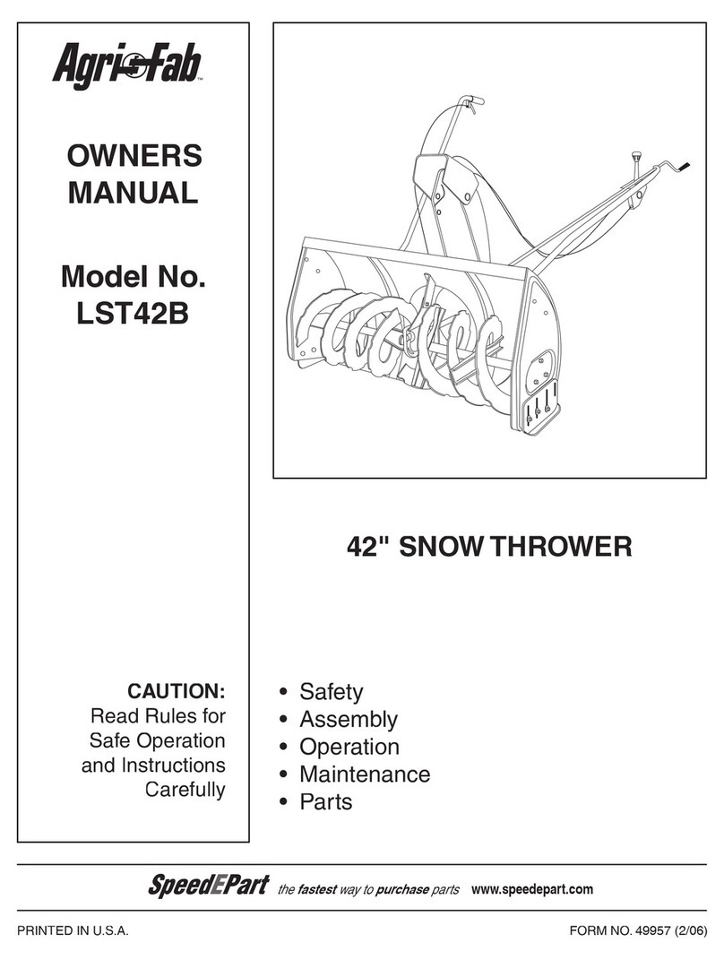
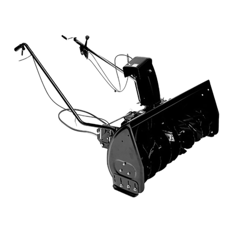
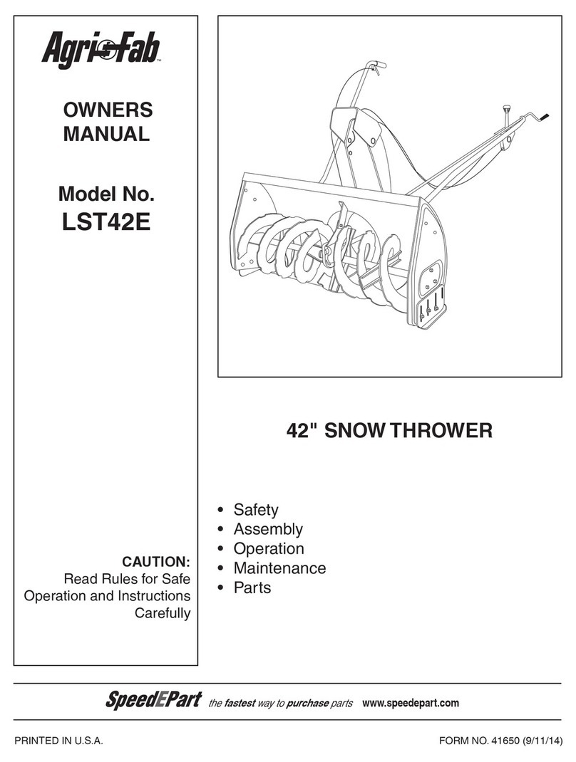
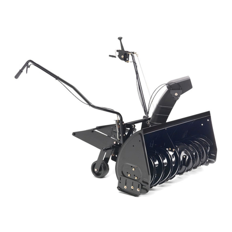
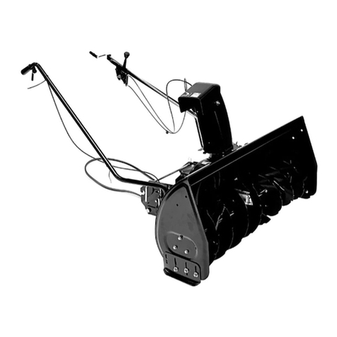
Agri-Fab LST42D User manual

Model No.
LST42D
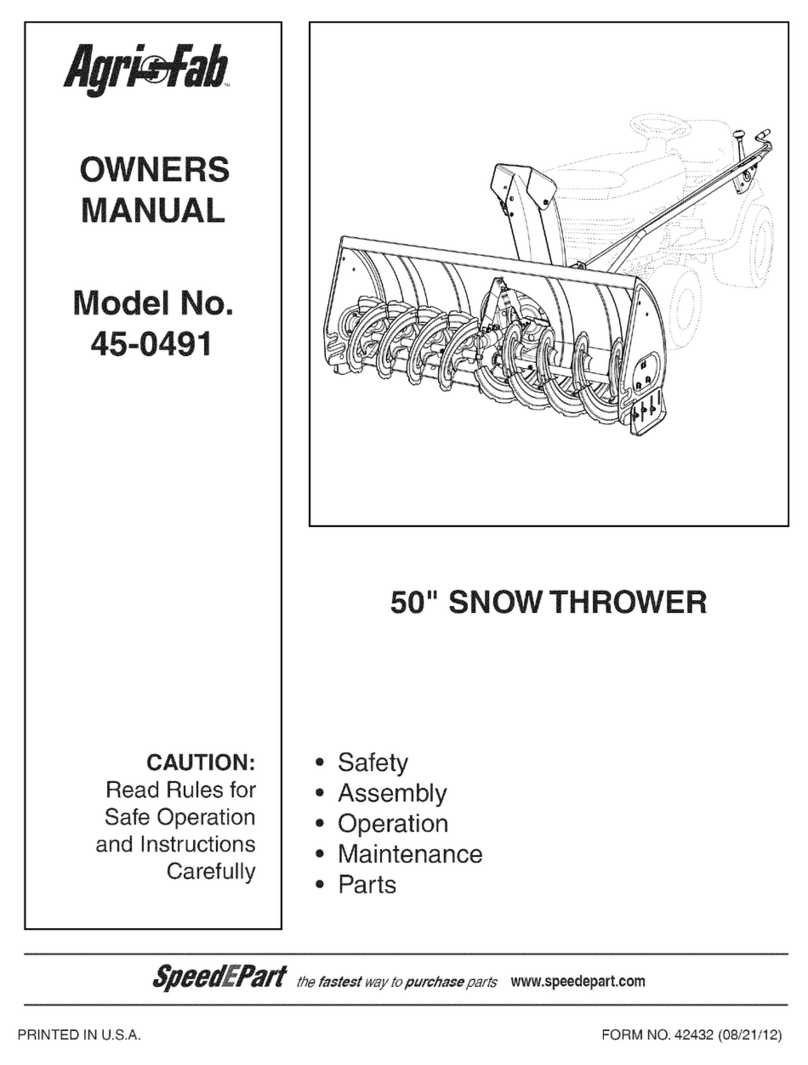
OWNERS
MANUAL
PRINTED IN U.S.A. FORM NO. 42320 (06/16/11)
CAUTION:
Read Rules for
Safe Operation
and Instructions
Carefully
• Safety
• Assembly
• Operation
• Maintenance
• Parts
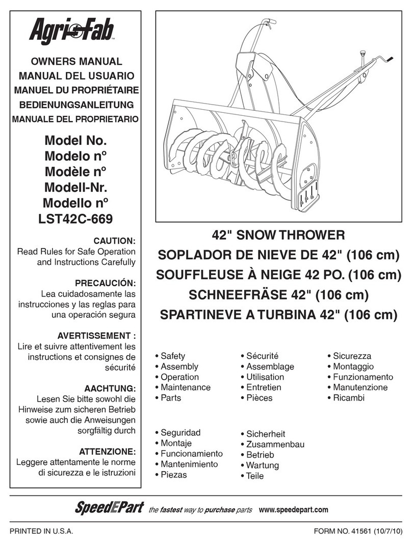
42" SNOW THROWER
the fastest way to purchase parts
www.speedepart.com
™

2
TABLE OF CONTENTS
ACCESSORIES.................................................................................................................................................................... 2
SAFETY RULES................................................................................................................................................................... 3
FULL SIZE HARDWARE CHART......................................................................................................................................... 4
CARTON CONTENTS.......................................................................................................................................................... 6
ASSEMBLY........................................................................................................................................................................... 7
OPERATION....................................................................................................................................................................... 25
MAINTENANCE ................................................................................................................................................................. 26
SERVICE AND ADJUSTMENTS........................................................................................................................................ 27
STORAGE .......................................................................................................................................................................... 28
TROUBLESHOOTING........................................................................................................................................................ 28
REPAIR PARTS ILLUSTRATION............................................................................................................................. 30,32,34
REPAIR PARTS LIST................................................................................................................................................ 31,33,34
SLOPE GUIDE ................................................................................................................................................................... 35
PARTS ORDERING/SERVICE ........................................................................................................................BACK COVER
IMPORTANT:
Rear wheel weights and tire chains are required to provide extra traction and
stabilitywhenusingthissnowthrowerattachment.Theseitemsareavailable
where you purchased your tractor.
WHEEL WEIGHTS TIRE CHAINS

3
SAFETY
Readandunderstandtheoperatinginstructionsbeforeusing.
Keeptheareaofoperationclearofallpersons,especiallysmallchildrenandpets.
Thoroughlyinspecttheareatobeclearedandremovealldoormats,sleds,boards,
wiresandotherforeignobjects.Useextremecautionwhenoperatingonorcrossing
gravelsurfaces.Neverdirectdischargeatbystandersorallowanyoneinfrontofthe
snow thrower.
Do not place hands near rotating parts. Keep clear of the
dischargeopeningatalltimes.
Do not place feet near rotating parts.
• Neverallowchildrentooperatetheequipment.
• Neverallowadultstooperatetheequipmentwithout
proper instruction.
• Disengageallclutchesandshiftintoneutralbefore
starting engine.
• Donotoperateequipmentwithoutwearingadequate
winteroutergarments.
• Wearsubstantialfootwearwhichwillprotectfeetand
improvefootingonslipperysurfaces.
• Checkfuelbeforestartingtheengine.Donotremove
thefuelcaporllthefueltankwhiletheengine
isrunningorhot.Donotllthefueltankindoors.
Gasolineisanextremelyammablefuel.
• Makesurethesnowthrowerheightisadjustedto
clearthetypesurfaceitwillbeusedon.
• Donotusethesnowthrowerwithoutwheelweights
attached to the tractor.
• Nevermakeanyadjustmentswhiletheengineis
running.
• Alwayswearsafetyglassesoreyeshieldduring
operationorwhileperformingadjustmentorrepair.
• Donotplacehandsorfeetnearrotatingparts.Keep
clearofthedischargeopeningatalltimes.
• Donotcarrypassengers.
• Afterstrikingaforeignobject,stoptheengine,remove
thewirefromthesparkplugandthenthoroughly
inspectthesnowthrowerfordamage.Repairany
damagebeforerestartingandoperatingthesnow
thrower.
• Ifthesnowthrowerstartstovibrateabnormally,stop
theengineimmediatelyandcheckforthecause.
Vibrationisgenerallyawarningoftrouble.
• Stoptheenginewheneveryouleavetheoperating
position,beforeuncloggingthesnowthroweror
makinganyadjustmentsorinspections.
• Takeallpossibleprecautionswhenleavingtheunit
unattended.Disengagetheattachmentclutchleveror
switch, lower the snow thrower, shift into neutral, set
theparkingbrake,stoptheengineandremovethekey.
• Whencleaning,repairingorinspecting,makecertain
allmovingpartshavestopped.Disconnectthespark
plugwireandkeepitawayfromtheplugtoprevent
accidental starting.
• Donotrunengineindoorsexceptwhentransporting
thesnowthrowerinoroutofthebuilding.Openthe
outsidedoors.Exhaustfumesaredangerous.
• Donotclearsnowacrossthefaceofslopes.Exercise
extremecautionwhenchangingdirectiononslopes.
Donotattempttoclearsteepslopes.Refertothe
slopeguideonpage35ofthismanual.
• Neveroperatethesnowthrowerwithoutguards,
plates or other safety protection devices in place.
• Neveroperatethesnowthrowernearglass
enclosures,automobiles,windowwells,dropoffs
etc.withoutproperadjustmentofthesnowthrower
discharge angle.
• Neverrunthesnowthrowerintosnowathighspeeds.
• Donotoverloadthesnowthrowercapacityby
attemptingtoclearsnowattoofastarate.
• Neveroperatethesnowthrowerathightransport
speedonslipperysurfaces.Lookbehindandusecare
whenbackingup.
• Watchfortrafcandstayalertwhencrossingor
operating near roadways.
• Disengagepowertothesnowthrowerwhen
transporting or when not in use.
• Useonlyattachmentsandaccessoriesapprovedby
themanufacturerofthesnowthrower(suchaswheel
weights,counterweights,cabsetc.)
• Neveroperatethesnowthrowerwithoutgoodvisibility.
184045
199683199682
4
E
BDG
HIK
O
F
X
U
Y
C
W
L
Q
S,T
R
Z
KK
EE
N
CC
BB
AA
NOT SHOWN ACTUAL SIZE
SHOWN ACTUAL SIZE
DD
M
J
JJ
FF GG
II
V
P
HH
A
LL
NN
MM
46938
43084
43182
43661
47631
47630 43350
44215
43682
44326
43080
48106
49933
710-0890A
43003 43088 43081
R19172410
47605, 43070 44695
43082
47810
47572
46584
47598
46959 731-0851A 711-0198
43055 43038
1643-60
23727
46963
726-0178
47788
47134 43343
48883
25780
HARDWARE PACKAGE CONTENTS

5
REF. QTY. DESCRIPTION REF. QTY. DESCRIPTION
U 2 Bowed Washer
V 6 Flanged Nut, 1/4"
W 1 Flanged Nut, 5/16"
X 10 Flanged Nut, 3/8"
Y 17 NylockNut,5/16"(2spareparts)
Z 2 HexLockNut,3/8"
AA 1 Spring
BB 3 Chute Keeper
CC 1 Trunnion
DD 2 Hairpin Cotter, 5/64"
EE 4 Hairpin Cotter, 1/8"
FF 1 Hairpin Cotter, 3/32"
GG 2 LockPin
HH 1 Plastic Cap
II 2 Nylon Tie
JJ 2 Chain, Tensioning
KK 2 TailReector
LL 1 SmallSpacer
MM 1 Large Spacer
NN 1 Pulley
A 1 Hex Bolt, 3/8" x 3-1/4"
B 2 Hex Bolt, 5/16" x 1-3/4"
C 4 Hex Bolt, 5/16" x 3/4"
D 6 Hex Bolt, 1/4" x 1"
E 6 HexBolt,3/8"x1"(ThreadForming)
F 2 HexBolt,5/16"x3/4"(ThreadForming)
G 6 Carriage Bolt, 3/8" x 1"
H 2 Carriage Bolt, 5/16" x 1-3/4"
I 2 Carriage Bolt , 5/16" x 1-1/4"
J 4 Carriage Bolt, 5/16" x 1"
K 2 Carriage Bolt, 5/16" x 3/4"
L 4 Shoulder Bolt
M 2 Shoulder Bolt
N 2 Shear Bolt (spare parts)
O 7 LockWasher,3/8"
P 7 Washer, 1/4"
Q 6 Washer, 5/16"
R 8 Washer, 1/2"
S 1 Washer, 3/8" (Thin)
T 3 Washer, 3/8"

6
CARTON CONTENTS
1. SuspensionArms(2)
2. Left Hand Side Plate
3. Right Hand Side Plate
4. Anti-rotationBracket
5. EngagementRod(Notusedonsomemodels)
6. EnginePulleyKeeper(Notusedonsomemodels)
7. ChuteCrankRodAssembly
8. SupportTube,CrankRod
9. LiftHandleandCable
10. CableBracket
11. L.H.HangerBracket(OutsideMounting)
12. R.H.HangerBracket(OutsideMounting)
13. ClutchIdlerAssembly
14. V-Belt, Drive (Short) #46989
15 V-Belt, Drive (Long) #48138
16. V-Belt,Auger(AttachedtoHousingAssembly)
17. ChuteandControlCableAssembly
18. HousingAssembly
19. L.H.HangerBracket(InsideMounting)
20. R.H.HangerBracket(InsideMounting)
HardwarePackage(StoredinsidePlasticKeg)
14
1245
6
12
9
8
10
20
19
11
17
16
15
18
13
7
3
47043
46948
24558
65450
65367
24394
25678
25679
64452
64451
46989
48138
47846

7
• Removeallpartsandhardwarepackagesfromthe
carton. Lay out parts and hardware and identify using
the illustrations on pages 4 and 6.
NOTE:Notallofthesuppliedpartsandhardwarewillbe
neededforyourparticulartractor.Unneededitemsmay
bediscardedafteryouhavecompletedassemblyand
checkedoperationofunit.DO NOT DISCARD the two
spareshearbolts(N)and5/16"nylocknuts(Y).Referto
theServiceandAdjustmentssectiononpage27.
REMOVAL OF PARTS FROM CARTON
TOOLS REQUIRED FOR ASSEMBLY
(2) 7/16" Wrenches
(2) 1/2" Wrenches
(2) 9/16" Wrenches
(2) 3/4" Wrenches
(1) Screw Driver
(1) Knife
ADDITIONAL ITEMS REQUIRED
General Purpose Grease
TRACTOR PREPARATION
Beforeperformingtheseinstructions,refertotheService
andAdjustmentssectionofyourtractorowner'smanual
forspecicsafetyinstructions.
• Allowengine,muferandexhaustdeectortocool
beforebeginning.
• Removeanyfrontorrearattachmentwhichis
mountedtoyourtractor.
•Removethemowerdeck.Refertoyourtractorowner's
manualforremovalinstructions.Markalllooseparts
andsaveforreassembly.
• Removethetractorhood.Refertoyourtractorowner's
manualforremovalinstructions.
CAUTION: Before starting to assemblethe
snowthrower,removethesparkplugwire(s),
settheparkingbrakeandremovethe key
fromthetractorignition.
FIGURE 2 RIGHT SIDE VIEW
IMPORTANT: Right hand (R.H.) and left hand (L.H.) side
ofthetractoraredeterminedfromtheoperatorsposition
while seated on the tractor.
REMOVE
FRONT SCREWS
REMOVE
BROWNING SHIELD
MOWER DECK
SUSPENSION
BRACKET
FIGURE 1
INSTRUCTIONS FOR TRACTORS WITH
SINGLE FRONT DECK SUSPENSION
BRACKET
STEP 2: (SEE FIGURE 2)
• Removethebrowningshieldfromthefrontofthe
tractorasshown.Holdontotheshieldasyouremove
thesecondscrewtopreventitfromfalling.
• Besuretoreinstallthebrowningshieldwhenso
instructed in step 3.
IDENTIFY YOU TRACTOR
STEP 1: (SEE FIGURE 1)
• Lookunderthefrontofyourtractor.Ifthereisasingle
mowerdecksuspensionbracketlocatedunderneath
themiddleofthefrontaxle,continueontostep
2. If your tractor does not have a mower deck
suspension bracket underneath the middle of the
front axle, skip to step 21 on page 13 for tractors
withdualsuspensionbrackets.
ASSEMBLY

8
STEP 4: (SEE FIGURE 4)
•Assembleashoulderbolt(L)anda3/8"washer(T)to
the outside of R.H. side plate, securing it with a 3/8"
angednut(X).RepeatforL.H.sideplate.
FIGURE 4 RIGHT SIDE VIEW
FIGURE 3 RIGHT SIDE VIEW
5/16"
NYLOCK
NUT (Y)
5/16" x 1"
CARRIAGE BOLT (J) ENGINE MOUNTING
PLATE
(4) 1/2" WASHERS (R)
(3) 3/8" FLANGE NUTS (X)
(3) 3/8" x 1"
CARRIAGE
BOLTS (G)
SEE NOTE
3/8" WASHER (T)
SHOULDER
BOLT (L)
3/8" FLANGED
NUT (X)
INSTALL SIDE PLATES
STEP 3: (SEE FIGURE 3)
• FastentheR.H.SidePlate(bendfacingout)tothe
frontthreeholesinthetractorframeusingthree3/8"
x1"carriagebolts(G),three1/2"washers(R)(see
note)andthree3/8"angenuts(X). For the rear hole,
usea5/16"x1"carriagebolt(J),a1/2"washer(R)
anda5/16"nylocknut(Y). Place the 1/2" washers (R)
betweenthetractorframeandthesideplate.Repeat
for L.H. side plate.
• Reinstallthebrowningshieldontothetractorframe
using the original screws.
NOTE:Ifthereisanenginemountingplate(shownwith
dottedlines)leavethe1/2washerofftheboltthatgoes
through the plate.
INSTALL HANGER BRACKETS AND SHOULDER
BOLTS TO OUTSIDE OF FRAME
STEP 5: (SEE FIGURE 5)
•Removethebolt,ifpresent,intheholedirectlybehind
thebrakerodontheleftsideofthetractorframe.
• AttachtheL.H.HangerBracket(tubefacingout)tothe
holeusinga5/16"x3/4"selfthreadingbolt(F).
• Installaroundheadshoulderbolt(M)intothehole
thatis9-1/2"totherearoftheboltyoujustinstalled.
Secureitwitha3/8"angenut(X)ontheinsideofthe
frame.
FIGURE 5 LEFT SIDE VIEW
5/16" x 3/4" SELF
THREADING BOLT (F)
L.H. HANGER
BRACKET
BRAKE ROD
3/8" FLANGED
NUT (X)
SHOULDER
BOLT (M)
5/16" x 3/4" SELF
THREADING BOLT (F)
R.H. HANGER
BRACKET
RIGHT END OF
BRAKE ROD
3/8" FLANGED
NUT (X)
SHOULDER
BOLT (M)
STEP 6: (SEE FIGURE 6)
•Removethebracket,ifpresent,fromtheholedirectly
behindtheendofthebrakerodontherightsideof
thetractorframe.Storethebracketandbolt.
• AttachtheR.H.HangerBrackettotheholeusinga
5/16"x3/4"selfthreadingbolt(F).
• Installaroundheadshoulderbolt(M)intothehole
thatis9-1/2"totherearoftheboltyoujustinstalled.
Secureitwitha3/8"angenut(X)ontheinsideofthe
frame.
FIGURE 6 RIGHT SIDE VIEW

9
3/8" X 3-1/4"
HEX BOLT
(A)
LARGE SPACER (MM)
PULLEY (NN)
3/8" LOCKWASHER (O)
3/8" HEX LOCK NUT (Z) 3/8"
WASHER (T)
LONG END
OF HUB
STEP 7: (SEE FIGURE 7)
• Attachthepulley(longendofhubfacingdown)and
the large spacer (MM) to the hole shown in the clutch/
idlerassembly.Usea3/8"x3-1/4"hexbolt(A),a3/8"
washer(T),a3/8"lockwasher(O)anda3/8"hexlock
nut (Z).
FIGURE 7
FIGURE 9
STEP 9: (SEE FIGURE 9)
• Attachthecablebrackettotheslotshowninthe
clutch/idlerassemblyusinga5/16"x3/4"carriage
bolt(K)anda5/16"nylocknut(Y).Placetheboltin
thefrontholeofthebracketandintheendoftheslot
closest to the pulley. Do not tighten yet.
CABLE
BRACKET
5/16" x 3/4"
CARRIAGE BOLT (K)
5/16" NYLOCK
NUT (Y)
THIS SECTION IS FOR TRACTORS WITH A
MANUAL ATTACHMENT CLUTCH
If your tractor has an electric attachment clutch go to
step 14 on page 11.
FIGURE 10
HEX BOLTS
(#48138)
DRIVE BELT
FLAT IDLER
PULLEYS
STOP
Didyouselectthecorrectdrivebeltforyour
tractor?Usingthewronglengthbeltmay
causeprematurebearingorbeltfailure.
STEP 10: (SEE FIGURE 10)
• Twodifferentlengthdrivebeltsareincludedwith
yoursnowthrower.Tractorswithmanualattachment
clutchesandsinglefrontdecksuspensionbracketsuse
the56"drivebeltwith#48138 printed on the outside of
thebelt.DO NOT USEtheotherbelt.
• Slightlyloosenthehexboltnexttotheatidlerpulley.
Installthedrivebeltdownbetweenthehexboltandthe
atidlerpulleywiththeatsideofthebeltagainstthe
pulley.Retightenthehexbolt.
• Loopthebeltaroundthelargev-pulley,placingit
betweenthev-pulleyandthehexboltnexttothepulley.
Placethebelttotheinsideoftheotheratidlerpulley.
5/16" NYLOCK
NUT (Y)
5/16" x 3/4"
HEX BOLT (C) TENSIONING CHAIN (JJ)
FIGURE 8
STEP 8: (SEE FIGURE 8)
• Attachthetwosuspensionarmstotherearofthe
clutch/idlerassemblyusingtwo5/16"x3/4"hexbolts
(C)and5/16"nylocknuts(Y)foreacharm.Placethe
armsontheoutsideoftheframewiththenotchesto
the rear.
• Insertatensioningchainthroughtheholeshownand
attachtheendlinktothespringontheloweridlerarm.

10
PIVOT LOCK PIN (GG)
(use this hole)
SHOULDER
BOLT (M)
L.H. HANGER
BRACKET
1/8" HAIRPIN
COTTER (EE)
NYLON TIE (II)
MOWER
CLUTCH
CABLE
FIGURE 12 VIEWED FROM LEFT SIDE
STEP 13: (SEE FIGURE 13)
• Assemblethedrivebeltontotheenginepulleyrst
and then onto the large pulley on top of the clutch/
idlerassembly.Thebeltmustbeplacedinsidethe
enginepulleybeltkeeper(s)andbetweenthelarge
pulleyandthekeeperboltnexttoit.
IMPORTANT: Do Notassemblethe"V"beltoutsideof
theenginepulleykeepersoroutsideofthekeeperbolt
next to the large pulley.
• Go to step 48 on page 21.
FIGURE 13 VIEWED FROM UNDERNEATH
ENGINE
PULLEY
ENGINE
PULLEY
Left Side
of Tractor
ENGINE
PULLEY
KEEPER
ENGINE
PULLEY
KEEPER
KEEPER BOLT
IDLER
PULLEY
CLUTCH/IDLER ASSEMBLY
FIGURE 11
5/64" HAIR
COTTER PIN
SPACER
1/4" WASHER
TRACTOR'S
CLUTCH CABLE
CABLE
BRACKET
GROOVE
5/64" HAIR
COTTER PIN (DD)
1/4" WASHER (P)
SPACER (LL)
TRACTOR'S
CLUTCH CABLE
CABLE
BRACKET
5/64" HAIR
COTTER PIN (DD)
ATTACH CLUTCH IDLER ASSEMBLY TO TRACTOR
STEP 12: (SEE FIGURE 12)
• Attachtheclutch/idlerassemblytothetractorframe.
Hookthenotchedsuspensionarmsontothetwo
shoulderbolts(M)assembledtotheoutsideofthe
tractorframe.Liftthefrontoftheassemblyandattach
ittotheR.H.andL.H.hangerbracketsusingtwopivot
lockpins(GG)and1/8"hairpincotters(EE).
• Looselyattachthemowerclutchcabletotheleftside
ofthetractorframewithanylontie(II).Do not pull
thenylontiecompletelytight.Thecablemayneedto
beremovedfromthenylontiewhenusingthemower
deck.
STEP 11: (SEE FIGURE 11)
• Findthecableclipthatisattachedtotheleftside
ofthetractorframeunderneaththefootrest.Open
theclipandremovethemowerclutchcable.Do not
removetheclipfromthetractorframe.Thecable
reattachestotheclipwhenusingthemowerdeck.
• Movetheattachmentclutchleveronthedashpanelto
the disengaged position.
• Placetheclutch/idlerassemblyontheoorontheleft
side of the tractor.
• Attachthetractor'smowerclutchcabletothecable
bracketontheclutch/idlerassembly.Securethecable
housingguide(groovedown)tothecablebracket
using the original collar and a 5/64" hair cotter pin (DD).
• Placeaspacer(LL)ontheweldedpinontheidler
arm.Hooktheendoftheclutchcablespringoverthe
pin and secure it with a 1/4" washer (P) and a 5/64"
hair cotter pin (DD).
• Aligncablebracketwithweldedpinandtightenthe
nutassembledinstep9.

11
THIS SECTION IS FOR TRACTORS WITH AN
ELECTRIC ATTACHMENT CLUTCH
STEP 14: (SEE FIGURE 14)
• Attachthetwosuspensionarmstotherearofthe
clutch/idlerassemblyusingtwo5/16"x3/4"hexbolts
(C)and5/16"nylocknuts(Y)foreacharm.Placethe
armsontheoutsideoftheframewiththenotchesto
the rear.
• Insertatensioningchainthroughtheholeshownand
attachtheendlinktothespringontheloweridlerarm.
FIGURE 14 FIGURE 16 VIEW OF BOTTOM
STEP 16: (SEE FIGURE 16)
• Hookoneendofthespringsuppliedinthepartsbag
throughtheendlinkofthetensioningchain.
• Withtheclutch/idlerassemblyturnedupsidedown,
hooktheotherendofthespringontotheendofthe
boltandnutwhichsecuretheidlerpulleytotheupper
idlerarm.Assemblea3/8"hexlocknut(Z)ontothe
boltandnut,leavingenoughgapbetweenthenutsfor
the spring to pivot freely.
• Attacha3/32"hairpincotter(FF)tothechain,placing
itinthefthlinkfromthespring.
CHAIN
(L.H. SIDE)
3/32" HAIR
COTTER PIN (FF)
5TH LINK
LEFT
SIDE
3/8" HEX
LOCK NUT (Z)
SPRING
RIGHT
SIDE
ATTACH
SPRING
HERE
STEP 15: (SEE FIGURE 15)
• Turntheclutch/idlerassemblyupsidedownandplace
the second tensioning chain (JJ) through the left front
hole.
FIGURE 15
TENSIONING CHAIN (JJ)
LEFT FRONT HOLE
STEP 17: (SEE TABLE 1)
•Twodifferentlengthdrivebeltsareincludedwith
yoursnowthrower.Usethetablebelowtoselect
thecorrectdrivebeltforyourtypetractor.Thepart
numberisprintedontheoutsideofthebelt.
• Setasidethebeltthatisnotforyourtractortoavoid
accidentally using it.
SELECT THE CORRECT DRIVE BELT
(Electric clutch tractors with a single front deck
suspension bracket)
55" BELT (PART #46989)
TRACTOR TYPE DECK SIZE CLUTCH TYPE
(LT) Lawn Tractor 38", 42" Electric
56" BELT (PART #48138)
TRACTOR TYPE DECK SIZE CLUTCH TYPE
(LT) Lawn Tractor 48" Electric
(GT) Garden Tractor 48", 54" Electric
TABLE 1
5/16" NYLOCK
NUT (Y)
5/16" x 3/4"
HEX BOLT (C) TENSIONING CHAIN (JJ)

12
STEP 19: (SEE FIGURE 18)
• Attachtheclutch/idlerassemblytothetractorframe.
Hookthenotchedsuspensionarmsontothetwo
shoulderbolts(M)assembledtotheoutsideofthe
tractorframe.Liftthefrontoftheassemblyandattach
ittotheR.H.andL.H.hangerbracketsusingtwopivot
lockpins(GG)and1/8"hairpincotters(EE).
PIVOT LOCK PIN (GG)
(use second hole) SHOULDER
BOLT (M)
1/8" HAIRPIN
COTTER (EE)
L.H. HANGER
BRACKET
FIGURE 18 VIEWED FROM LEFT SIDE
STEP 20: (SEE FIGURE 19)
• Assemblethedrivebeltontotheenginepulleyrst
and then onto the large pulley on top of the clutch/
idlerassembly.Placethebelttotheinsideoftheidler
pulleyandthebeltkeeperboltlocatedbesidethe
large pulley.
• Placetensiononthebeltbypullingtheleftside
tensioning chain (JJ) out as far as the 3/32" hairpin
cotter in the chain will allow. Secure the chain in this
positionbyinsertinga1/8"hairpincotter(EE)through
the chain.
IMPORTANT: Do Notassemblethedrivebeltaroundthe
outsideofthekeeperboltbesidethelargepulley.
• Go to step 48 on page 21.
FIGURE 19 VIEWED FROM UNDERNEATH
1/8" HAIRPIN
COTTER (EE)
ENGINE
PULLEY
ENGINE
PULLEY
KEEPER
BOLT
IDLER
PULLEY
CHAIN (JJ)
(L.H. SIDE)
FIGURE 17
STEP 18: (SEE FIGURE 17)
• Turntheclutch/idlerassemblyrightsideup.
• Slightlyloosenthehexboltnexttotheatidlerpulley.
Installthedrivebeltdownbetweenthehexboltandthe
atidlerpulleywiththeatsideofthebeltagainstthe
pulley.Retightenthehexbolt.
• Loopthebeltaroundthelargev-pulley,placingit
betweenthev-pulleyandthehexboltnexttothepulley.
STOP
Didyouchoosethecorrectdrivebeltfor
yourtractor?Usingthewronglengthbelt
maycauseprematurebearingorbeltfailure.
CLUTCH/IDLER ASSEMBLY
HEX BOLTS
DRIVE BELT
FLAT IDLER
PULLEY

13
STEP 22: (SEE FIGURE 21)
• FastentheR.H.SidePlate(bendfacingout)tothe
frontthreeholesshowninthetractorframeusing
three3/8"x1"threadformingbolts(E),three3/8"
lockwashers(O)andone1/2"washer(R)placedon
thethirdboltasashimbetweenthesideplateand
theframe.Tightenallbolts.RepeatfortheL.H.side.
NOTE:Ifyouinstalledaboltinthefourthholeinstep21,
assemblea5/16"angenut(W)ontotheboltafterthe
side plate is installed.
• Go to step 25 on this page.
(3) 3/8" x 1"
THREAD FORMING
BOLTS (E)
5/16" FLANGED
NUT (W)
(SEE NOTE) (3) 3/8" LOCK
WASHERS (O)
1/2" WASHER (R)
5/16" x 1"
CARRIAGE BOLT (J)
(SEE NOTE)
FIGURE 21 RIGHT SIDE VIEW
FRONT SUSPENSION
BRACKET
REMOVE BOLTS
IF PRESENT
FIGURE 22 RIGHT SIDE VIEW
STEP 23: (SEE FIGURE 22)
•Removeanyboltsfoundintheholesshown.
STEP 21: (SEE FIGURE 20)
•Removeboltsfromfrontthreeholesshown.
• Ifaboltispresentinthefourthhole,replaceitwitha
5/16"x1"carriagebolt(J)withoutanut.Thebracket
fastenedtoinsideofframemustremaininplace.
FRONT
SUSPENSION
BRACKET
REPLACE BOLT
(IF PRESENT)
REMOVE BOLTS
(IF PRESENT)
FIGURE 20 RIGHT SIDE VIEW
INSTRUCTIONS FOR TRACTORS WITH DUAL
FRONT DECK SUSPENSION BRACKETS
FASTEN SIDE PLATES TO TRACTOR
Ifyourtractorresemblesgure20,startwithstep21.
Ifyourtractorresemblesgure22,startwithstep23.
STEP 25: (SEE FIGURE 24)
•Assembleashoulderbolt(L)anda3/8"washer(T)to
theoutsideofeachsideplate,securingthemwitha
3/8"angednut(X).
FIGURE 24 RIGHT SIDE VIEW
3/8" WASHER (T)
SHOULDER
BOLT (L)
3/8" FLANGED
NUT (X)
STEP 24: (SEE FIGURE 23)
•FastentheR.H.SidePlate(bendfacingout)tothe
threeholesshowninthetractorframe.Usethree3/8"
x1"threadformingbolts(E),3/8"lockwashers(O)
and1/2"washers(R).Usethe1/2"washersasshims
betweentheSidePlateandthetractorframe.Tighten
allboltsandrepeatfortheL.H.side.
NOTE:Iftheboltinsertsfreelyintothefronthole,assemble
a3/8"angednut(X)ontothebolt.
(3) 3/8" x 1"
THREAD FORMING
BOLTS (E)
(3) 3/8" LOCK
WASHERS (O)
3/8" FLANGED NUT (X)
(SEE NOTE)
(3) 1/2" WASHERS (R)
FIGURE 23 RIGHT SIDE VIEW

14
FIGURE 28 RIGHT SIDE VIEW
INSTALLING HANGER BRACKETS
Forbetterclearance,lowerthetractor'ssuspensionarms
usingtheattachmentliftlever.
STEP 26: (SEE FIGURE 25 or 26)
On Tractors With Foot Rest Brackets
•RemovetheboltandnutthatfastentheL.H.andR.H.
footrestbracketstotheframe.
• AttachtheL.H.HangerBracket(marked"L")tothe
insideofthetractorframeusingtwo3/8"x1"carriage
bolts(G)and3/8"angednuts(X).Boltheadsgoon
insideoftractorframe.RepeatfortheR.H.side.
FIGURE 26 LEFT SIDE VIEW
FIGURE 25 LEFT SIDE VIEW
On Tractors Without Foot Rest Brackets
• Findtheemptyholebeneaththefootrest.Attachthe
L.H.HangerBracket(marked"L")totheinsideofthe
frameusinga3/8"x1"carriagebolt(G)anda3/8"
angednut(X).Boltheadgoesoninsideoftractor
frame.RepeatfortheR.H.side.
STEP 28: (SEE FIGURE 28)
• Assembleashoulderbolt(L)and3/8"angednut(X)
totheR.H.sideofthetractorframe,usingtherst
emptyholetotherearoftheR.H.hangerbracket.Bolt
goesoninsideofframe.
FIGURE 27 LEFT SIDE VIEW
INSTALLING SHOULDER BOLTS
STEP 27: (SEE FIGURE 27)
• Removethebolt,washerandnutwhichfastenthe
swaybarbrackettotheL.H.sideofthetractorframe.
Replacewithashoulderbolt(L)anda3/8"anged
nut(X).Boltgoesoninsideofframe.
BOLT REMOVED
FROM THIS HOLE
SWAY BAR
BRACKET
SHOULDER BOLT (L)
3/8"
FLANGED
NUT (X)
3/8" x 1"
CARRIAGE
BOLT (G)
3/8" FLANGED
NUT (X)
L.H. HANGER
BRACKET
SUSPENSION ARM
SHOULDER BOLT (L)
3/8"
FLANGED
NUT (X)
R.H. HANGER BRACKET
BOLT REMOVED
FROM THIS HOLE
3/8" x 1"
CARRIAGE
BOLT (K)
3/8" FLANGED
NUT (X)
L.H. HANGER
BRACKET
SUSPENSION ARM

15
INSTALLING CLUTCH/IDLER ASSEMBLY
This section covers the installation of the Clutch/Idler
assemblytotractorswithattachmentclutchesthatare
eitherrodoperated(p.15),cableoperated(p.17)or
electric (p. 19). Use the appropriate instructions for your
tractor.
ROD OPERATED MANUAL ATTACHMENT CLUTCH
STEP 29: (SEE FIGURE 29)
• Movetheattachmentclutchleveronthedashpanelto
the disengaged (down) position.
• Screwthetrunnion(CC)ontotheendofthesnow
throwerengagementrod.
• Locatetheclutcharm(wherethemowerclutchrod
was connected) underneath the right hand side the
tractor,justtotheinsideofthesuspensionarm.If
there is an extension attached to the clutch lever, the
extension,boltandnutmustberemovedandstored
withthemowerdeck.
IMPORTANT: Re-attach the extension to the clutch
leverbeforereinstallingthemowerdeck.
• Positiontheengagementrodtotheinsideofthe
clutcharmandinsertthedrilledendoftherod
throughthearm.Securewitha5/64"hairpincotter
(DD).
FIGURE 29 RIGHT SIDE VIEW
ENGAGEMENT ROD
5/64" HAIRPIN
COTTER (DD)
TRACTOR'S CLUTCH ARM
SUSPENSION ARM
TRUNNION (CC)
REMOVE EXTENSION,
BOLT AND NUT
(IF PRESENT)
STEP 30: (SEE FIGURE 30)
• Attachthetwosuspensionarmstotheinsideofthe
clutch/idlerassemblyusingtwo5/16"x3/4"hexbolts
(C),5/16"washers(Q)and5/16"nylocknuts(Y)for
eacharm.Placethewashersbetweenthearmsand
theassemblyframe.
• Insertatensioningchainthroughtheholeshownand
attachtheendlinktothespringontheloweridlerarm.
FIGURE 30
5/16" x 3/4"
HEX BOLT (C)
5/16" NYLOCK
NUT (Y)
TENSIONING CHAIN (JJ)
5/16" WASHER (Q)
FIGURE 31
STOP
Didyouchoosethecorrectdrivebeltfor
yourtractor?Usingthewronglengthbelt
maycauseprematurebearingorbeltfailure.
HEX BOLTS
DRIVE BELT
FLAT IDLER
PULLEY
(#46989)
STEP 31: (SEE FIGURE 31)
• Twodifferentlengthdrivebeltsareincludedwith
yoursnowthrower.Tractorswithmanualattachment
clutchesanddualfrontdecksuspensionbracketsuse
the55"drivebeltwith#46989 printed on the outside
ofthebelt.DO NOT USEtheotherbelt.
• Slightlyloosenthehexboltnexttotheatidlerpulley.
Installthedrivebeltdownbetweenthehexboltandthe
atidlerpulleywiththeatsideofthebeltagainstthe
pulley.Retightenthehexbolt.
• Loopthebeltaroundthelargev-pulley,placingit
betweenthev-pulleyandthehexboltnexttothepulley.

16
FIGURE 33 RIGHT SIDE VIEW
FIGURE 32 RIGHT SIDE VIEW
PIVOT LOCK PIN (GG)
(use second hole)
1/8" HAIRPIN COTTER (EE)
ENGAGEMENT
ROD
STEP 33: (SEE FIGURE 33)
• Makesuretheattachmentclutchleveronthedash
panel is in the disengaged (down) position.
• Pivottheupperidlerarmsothatitrestsagainstthe
stopboltandispointingtowardthefrontasshown.
Screw the trunnion (CC) along the threads of the
engagementroduntilitisalignedatthefrontendof
theidlerarmslot.Attachthetrunnion(CC)totheslot
using the 3/8" thin washer (S) and a 5/64" hairpin
cotter (DD).
• Removetheenginepulleykeeperfromthesideof
thetractorframebyremovingthewasherandnut
thatsecurethekeeper.Attachthenewpulleykeeper
supplied with the snow thrower, reusing the original
bolt,washerandnut.
NOTE:Sometractorsmayalreadybeequippedwitha
pulleykeeperthatisidenticaltothenewonesupplied.
IDLER ARM
5/64" HAIRPIN
COTTER (DD)
TRUNNION (CC)
STOP BOLT
3/8" THIN
WASHER (S)
NEW ENGINE PULLEY KEEPER WITH
ORIGINAL BOLT, NUT AND WASHER
STEP 34: (SEE FIGURE 34)
• Assembletheshort"V"beltontotheenginepulley
and then onto the large pulley on top of the clutch/
idlerassembly.Thebeltmustbeplacedtotheinside
oftheenginepulleykeeper,theidlerpulleyandthe
keeperboltlocatedbesidethelargepulley.
IMPORTANT: Do Notassemblethe"V"beltaroundthe
outsideoftheenginepulleykeeperorthekeeperbolt.
• Go to step 48 on page 21.
FIGURE 34 VIEWED FROM UNDERNEATH
ENGINE
PULLEY
KEEPER BOLT
IDLER
PULLEY
ENGINE
PULLEY
KEEPER
Left Side
of Tractor
CLUTCH/IDLER ASSEMBLY
STEP 32: (SEE FIGURE 32)
• Besuretoliftupthefrontendoftheengagementrod
asshownwhenperformingthenextoperation.You
cantemporarilysupporttherodusingarubberband
tiedtotheenginepulleykeeper.
• Attachtheclutch/idlerassemblytothetractorframe
asfollows.Hooktheassembly'snotchedarmsonto
thetwoshoulderboltsyouassembledtotheinside
ofthetractorframe.Liftthefrontoftheassemblyand
attachittotheR.H.andL.H.hangerbracketsusing
twopivotlockpins(GG)and1/8"hairpincotters(EE).

17
FIGURE 36
FIGURE 38
STEP 36: (SEE FIGURE 36)
• Assemblethecablebrackettotheclutch/idler
assemblyusingtwo5/16"x3/4"carriagebolts(K)and
5/16"nylocknuts(Y).Usethetwofrontholesinthe
cablebracketifyourtractorhasa42"mowerdeck.
Usethetworearholesifyourtractorhasa46"mower
deck.
STEP 38: (SEE FIGURE 38)
• Movetheattachmentclutchleveronthedashpanelto
the disengaged (down) position.
• Placetheclutch/idlerassemblyontheoorontheright
side of the tractor.
• Attachthetractor'sclutchcabletothecablebracket.
Securethecablehousingguide(groovedown)tothe
cablebracketusingtheoriginalcollaranda5/64"hair
cotter pin (DD).
• Placeaspacer(LL)ontheweldedpinontheidlerarm.
Hooktheendoftheclutchspringoverthepinand
secure it with a 1/4" washer (P) and a 5/64" hair cotter
pin (DD).
CABLE
BRACKET
5/16" x 3/4"
CARRIAGE BOLT (K)
5/16" NYLOCK
NUT (Y)
42"
DECKS
46"
DECKS
TRACTOR'S
CLUTCH CABLE
5/64" HAIR
COTTER PIN (DD)
1/4" WASHER (P)
SPACER (LL)
5/64" HAIR
COTTER PIN (DD)
STEP 35: (SEE FIGURE 35)
• Attachthetwosuspensionarmstotherearofthe
clutch/idlerassemblyusingtwo5/16"x3/4"hexbolts
(C),5/16"washer(Q)and5/16"nylocknuts(Y)for
eacharm.Placethearmsontheoutsideoftheframe
with the notches to the rear.
• Insertatensioningchainthroughtheholeshownand
attachtheendlinktothespringontheloweridlerarm.
FIGURE 35
5/16" x 3/4"
HEX BOLT (C)
5/16" NYLOCK
NUT (Y)
TENSIONING CHAIN (JJ)
5/16" WASHER (Q)
CABLE OPERATED MANUAL ATTACHMENT CLUTCH
FIGURE 37
HEX BOLTS
DRIVE BELT
FLAT IDLER
PULLEY
(#46989)
STEP 37: (SEE FIGURE 37)
• Twodifferentlengthdrivebeltsareincludedwith
yoursnowthrower.Tractorswithmanualattachment
clutchesanddualfrontdecksuspensionbracketsuse
the55"drivebeltwith#46989 printed on the outside
ofthebelt.DO NOT USEtheotherbelt.
STOP
Didyouchoosethecorrectdrivebeltfor
yourtractor?Usingthewronglengthbelt
maycauseprematurebearingorbeltfailure.
• Slightlyloosenthehexboltnexttotheatidlerpulley.
Installthedrivebeltdownbetweenthehexboltandthe
atidlerpulleywiththeatsideofthebeltagainstthe
pulley.Retightenthehexbolt.
• Loopthebeltaroundthelargev-pulley,placingit
betweenthev-pulleyandthehexboltnexttothepulley.

18
FIGURE 40 VIEWED FROM UNDERNEATH
FIGURE 39
STEP 40: (SEE FIGURE 40)
• Assembletheshort"V"beltontotheenginepulley
and then onto the large pulley on top of the clutch/idler
assembly.Thebeltmustbeplacedtotheinsideofthe
enginepulleykeeper,theidlerpulleyandthekeeper
boltlocatedbesidethelargepulley.
IMPORTANT: Do Notassemblethe"V"beltaroundthe
outsideoftheenginepulleykeeperorthekeeperbolt.
• Go to step 48 on page 21.
STEP 39: (SEE FIGURE 39)
• Removetheenginepulleykeeperfromthesideof
thetractorframebyremovingthewasherandnut
thatsecurethekeeper.Attachthenewpulleykeeper
supplied with the snow thrower, reusing the original
bolt,washerandnut.
NOTE:Sometractorsmayalreadybeequippedwitha
pulleykeeperthatisidenticaltothenewonesupplied.
• Attachtheclutch/idlerassemblytothetractorframe
asfollows.Hooktheassembly'snotchedarmsonto
thetwoshoulderboltsyouassembledtotheinside
ofthetractorframe.Liftthefrontoftheassemblyand
attachittotheR.H.andL.H.hangerbracketsusing
twopivotlockpins(GG)and1/8"hairpincotters(EE).
NEW ENGINE PULLEY KEEPER WITH
ORIGINAL BOLT, NUT AND WASHER
PIVOT LOCK PIN (GG)
(use second hole)
1/8" HAIRPIN COTTER (EE)
ENGINE
PULLEY
KEEPER BOLT
IDLER
PULLEY
ENGINE
PULLEY
KEEPER
Left Side
of Tractor
CLUTCH/IDLER ASSEMBLY

19
ELECTRIC ATTACHMENT CLUTCHES
FIGURE 42
TENSIONING CHAIN (JJ)
LEFT FRONT HOLE
FIGURE 43 VIEW OF BOTTOM
STEP 43: (SEE FIGURE 43)
• Hookthespringfromthepartsbagthroughtheendof
the tensioning chain.
• Hooktheotherendofthespringontothebottomof
theboltandnutwhichsecuretheidlerpulleytothe
upperidlerarm.Holdtheboltheadandassemblea
3/8"hexlocknut(Z)ontothebolt,leavingenough
spaceforthespringtopivotfreelybetweenthetwo
nuts.
• Attacha3/32"hairpincotter(FF)tothechain,placing
itinthefthlinkfromthespring.
CHAIN
(L.H. SIDE)
3/32" HAIR
COTTER PIN (FF)
5TH LINK
LEFT
SIDE
3/8" HEX
LOCK NUT (Z)
SPRING
RIGHT
SIDE
ATTACH
SPRING
HERE
STEP 44: (SEE TABLE 2)
•Twodifferentlengthdrivebeltsareincludedwith
yoursnowthrower.Usethetablebelowtoselect
thecorrectdrivebeltforyourtypetractor.Thepart
numberisprintedontheoutsideofthebelt.
• Setasidethebeltthatisnotforyourtractortoavoid
accidentally using it.
55" BELT (PART #46989)
TRACTOR TYPE DECK SIZE CLUTCH TYPE
56" BELT (PART #48138)
TRACTOR TYPE DECK SIZE CLUTCH TYPE
(LT) Lawn Tractor 48" Electric
(LT) Lawn Tractor 38", 42", 46" Electric
TABLE 2
STEP 41: (SEE FIGURE 41)
• Attachthetwosuspensionarmstotherearofthe
clutch/idlerassemblyusingtwo5/16"x3/4"hexbolts
(C),5/16"washer(Q)and5/16"nylocknuts(Y)for
eacharm.Placethearmsontheoutsideoftheframe
with the notches to the rear.
• Insertatensioningchainthroughtheholeshownand
attachtheendlinktothespringontheloweridlerarm.
FIGURE 41
STEP 42: (SEE FIGURE 42)
• Pacetheextratensioningchain(JJ)throughtheleft
frontholeintheclutch/idlerassemblyandthenturn
theassemblyupsidedown.
5/16" x 3/4"
HEX BOLT (C)
5/16" NYLOCK
NUT (Y)
TENSIONING CHAIN (JJ)
5/16" WASHER (Q)

20
FIGURE 46 VIEWED FROM UNDERNEATH
1/8" HAIRPIN
COTTER (EE)
ENGINE
PULLEY
ENGINE
PULLEY
Left Side
of Tractor
KEEPER
BOLT
IDLER
PULLEY
STEP 47: (SEE FIGURE 46)
• Assemblethedrivebeltontotheenginepulleyand
then onto the large pulley on top of the clutch/idler
assembly.Thebeltmustbeplacedtotheinsideof
theidlerpulleyandthekeeperboltlocatedbesidethe
large pulley.
• Placetensiononthebeltbypullingtheleftside
tensioning chain out as far as the 3/32" hairpin cotter
(FF)willallow.Securethechaininthispositionby
inserting a 1/8" hairpin cotter (EE) through the chain.
IMPORTANT: Do Notassemblethe"V"beltaroundthe
outsideoftheenginepulleykeeperorthekeeperbolt.
STEP 46: (SEE FIGURE 45)
• Attachtheclutch/idlerassemblytothetractorframe
asfollows.Hooktheassembly'snotchedarmsonto
thetwoshoulderboltsyouassembledtotheinside
ofthetractorframe.Liftthefrontoftheassemblyand
attachittotheR.H.andL.H.hangerbracketsusing
twopivotlockpins(GG)and1/8"hairpincotters(EE).
FIGURE 45 RIGHT SIDE VIEW
PIVOT LOCK PIN (GG)
(use second hole)
1/8" HAIRPIN COTTER (EE)
CLUTCH/IDLER ASSEMBLY
HEX BOLTS
DRIVE BELT
FLAT IDLER
PULLEY
FIGURE 44
STOP
Didyouchoosethecorrectdrivebeltfor
yourtractor?Usingthewronglengthbelt
maycauseprematurebearingorbeltfailure.
STEP 45: (SEE FIGURE 44)
• Turntheclutch/idlerassemblyrightsideup.
• Slightlyloosenthehexboltnexttotheatidlerpulley.
Installthedrivebeltdownbetweenthehexboltandthe
atidlerpulleywiththeatsideofthebeltagainstthe
pulley.Retightenthehexbolt.
• Loopthebeltaroundthelargev-pulley,placingit
betweenthev-pulleyandthehexboltnexttothepulley.
Placethebelttotheinsideoftheotheratidlerpulley.
Table of contents
Other Agri-Fab Snow Blower manuals

Agri-Fab
Agri-Fab LST42C-669 User manual

Agri-Fab
Agri-Fab LST42F User manual

Agri-Fab
Agri-Fab HUSQVARNA 966 41 60-01 User manual

Agri-Fab
Agri-Fab 45-0491 User manual

Agri-Fab
Agri-Fab LST42E User manual

Agri-Fab
Agri-Fab 45-0418 User manual

Agri-Fab
Agri-Fab LST 42 User manual

Agri-Fab
Agri-Fab 45-0418 User manual

Agri-Fab
Agri-Fab 45-0491 User manual

Agri-Fab
Agri-Fab LST42G User manual