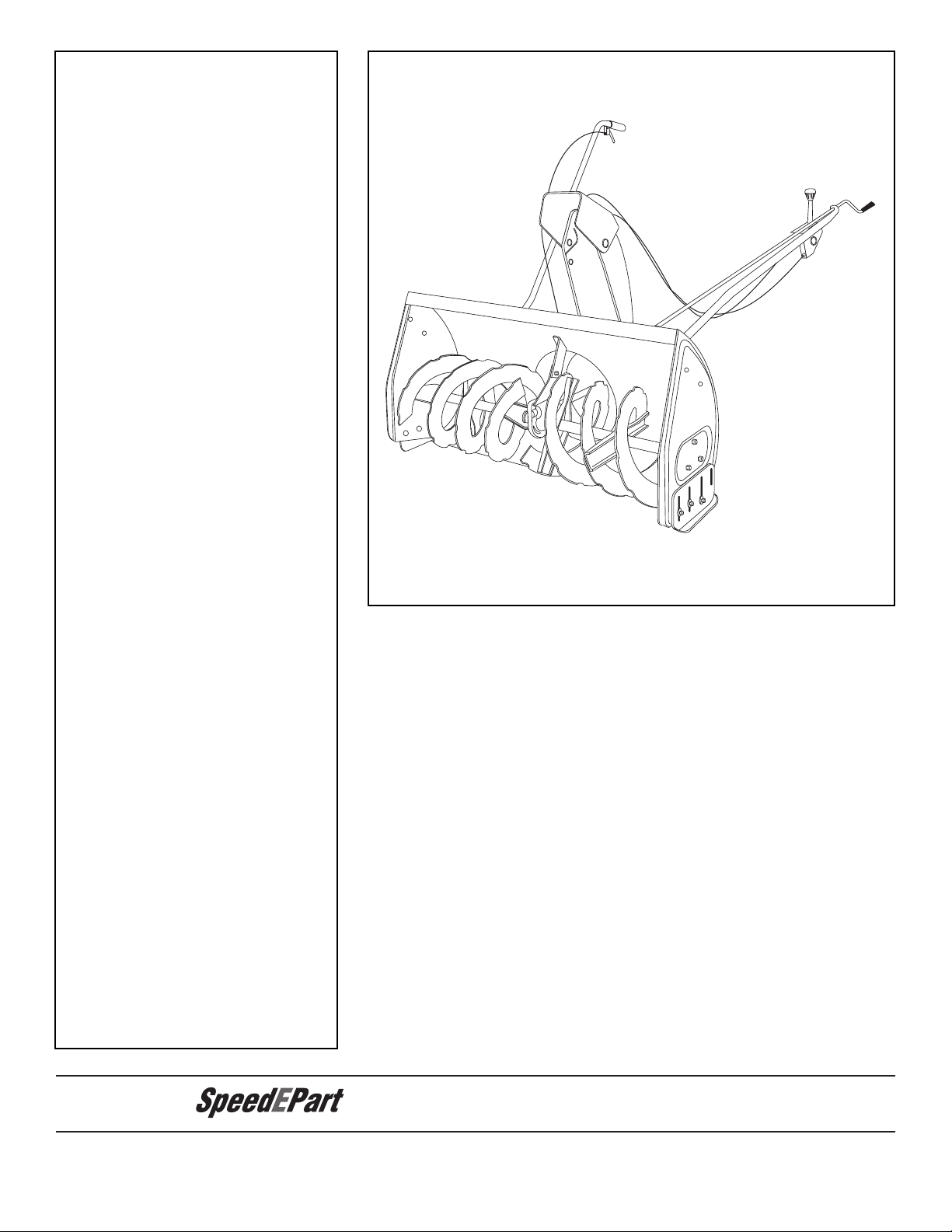
Agri-Fab LST42G User manual

Model No.
LST42G
OWNERS
MANUAL
PRINTED IN U.S.A. FORM NO. 28156 rev. (05/09/16)
42" SNOW THROWER
the fastest way to purchase parts
www.speedepart.com
CAUTION:
Read Rules for Safe
Operation and Instructions
Carefully
• Safety
• Assembly
• Operation
• Maintenance
• Parts

2
TABLE OF CONTENTS
SAFETY RULES................................................................................................................................................................... 3
FULL SIZE HARDWARE CHART......................................................................................................................................... 4
CARTON CONTENTS .......................................................................................................................................................... 6
ASSEMBLY........................................................................................................................................................................... 7
OPERATION....................................................................................................................................................................... 25
MAINTENANCE ................................................................................................................................................................. 26
SERVICE AND ADJUSTMENTS ........................................................................................................................................ 27
STORAGE .......................................................................................................................................................................... 28
TROUBLESHOOTING........................................................................................................................................................ 29
REPAIR PARTS ILLUSTRATION............................................................................................................................. 30,32,34
REPAIR PARTS LIST................................................................................................................................................ 31,33,34
SLOPE GUIDE ................................................................................................................................................................... 35
PARTS ORDERING/SERVICE ........................................................................................................................BACK COVER
IMPORTANT:
Rear wheel weights and tire chains are required to
provideextratractionandstabilitywhenusingthissnow
throwerattachment.Theseitemsareavailablewhere
you purchased your tractor.
WHEEL WEIGHTS TIRE CHAINS

3
SAFETY
Readandunderstandtheoperatinginstructionsbeforeusing.
Keeptheareaofoperationclearofallpersons,especiallysmallchildrenandpets.
Thoroughlyinspecttheareatobeclearedandremovealldoormats,sleds,boards,
wiresandotherforeignobjects.Useextremecautionwhenoperatingonorcrossing
gravelsurfaces.Neverdirectdischargeatbystandersorallowanyoneinfrontofthe
snow thrower.
Do not place hands near rotating parts. Keep clear of the
dischargeopeningatalltimes.
Do not place feet near rotating parts.
• Neverallowchildrentooperatetheequipment.
• Neverallowadultstooperatetheequipmentwithout
proper instruction.
• Disengageallclutchesandshiftintoneutralbefore
starting engine.
• Donotoperateequipmentwithoutwearingadequate
winteroutergarments.
• Wearsubstantialfootwearwhichwillprotectfeetand
improvefootingonslipperysurfaces.
• Checkfuelbeforestartingtheengine.Donotremove
thefuelcaporllthefueltankwhiletheengine
isrunningorhot.Donotllthefueltankindoors.
Gasolineisanextremelyammablefuel.
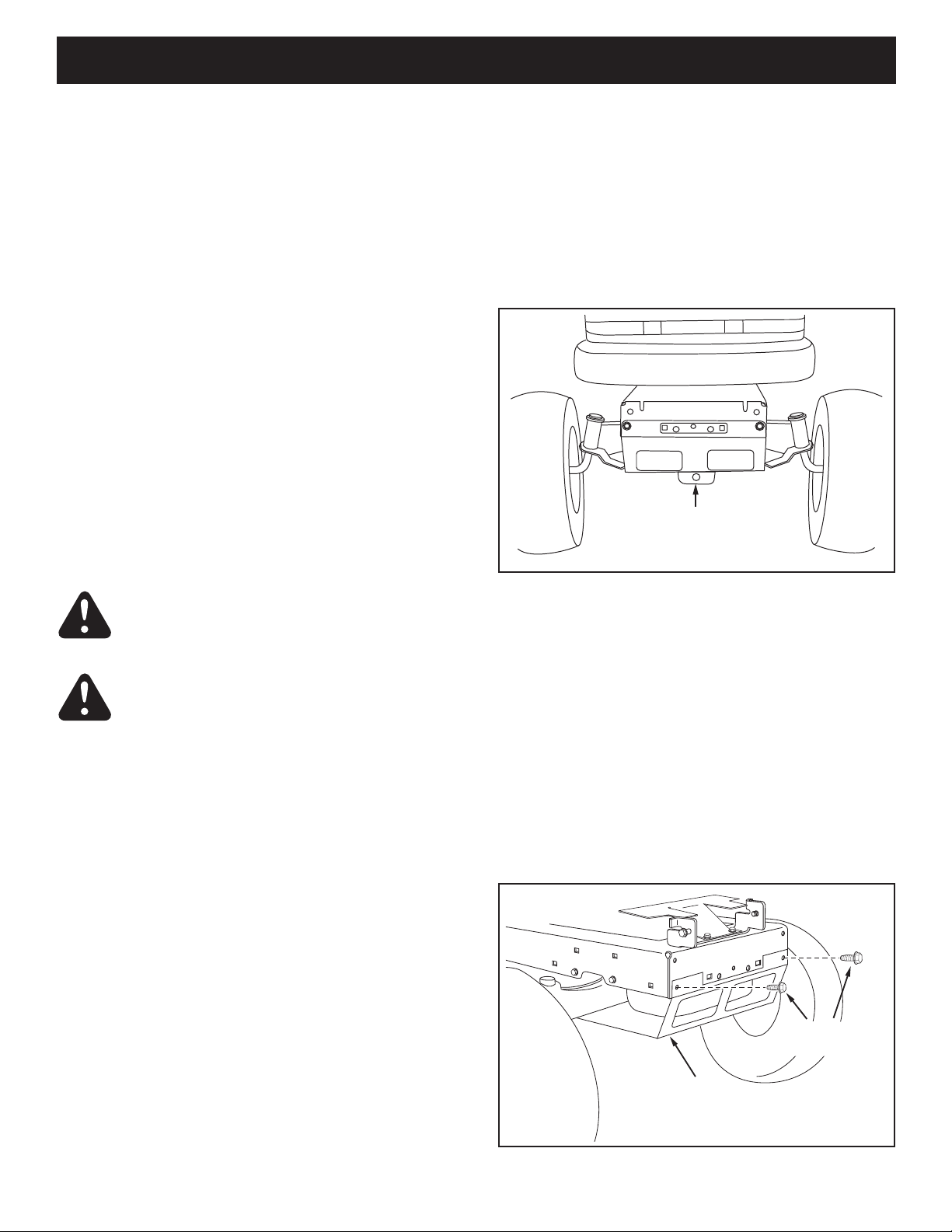
• Makesurethesnowthrowerheightisadjustedto
clearthetypesurfaceitwillbeusedon.
• Donotusethesnowthrowerwithoutwheelweights
attached to the tractor.
• Nevermakeanyadjustmentswhiletheengineis
running.
• Alwayswearsafetyglassesoreyeshieldduring
operationorwhileperformingadjustmentorrepair.
• Donotplacehandsorfeetnearrotatingparts.Keep
clearofthedischargeopeningatalltimes.
• Donotcarrypassengers.
• Afterstrikingaforeignobject,stoptheengine,remove
thewirefromthesparkplugandthenthoroughly
inspectthesnowthrowerfordamage.Repairany
damagebeforerestartingandoperatingthesnow
thrower.
• Ifthesnowthrowerstartstovibrateabnormally,stop
theengineimmediatelyandcheckforthecause.
Vibrationisgenerallyawarningoftrouble.
• Stoptheenginewheneveryouleavetheoperating
position,beforeuncloggingthesnowthroweror
makinganyadjustmentsorinspections.
• Takeallpossibleprecautionswhenleavingtheunit
unattended.Disengagetheattachmentclutchleveror
switch, lower the snow thrower, shift into neutral, set
theparkingbrake,stoptheengineandremovethekey.
• Whencleaning,repairingorinspecting,makecertain
allmovingpartshavestopped.Disconnectthespark
plugwireandkeepitawayfromtheplugtoprevent
accidental starting.
• Donotrunengineindoorsexceptwhentransporting
thesnowthrowerinoroutofthebuilding.Openthe
outsidedoors.Exhaustfumesaredangerous.
• Donotclearsnowacrossthefaceofslopes.Exercise
extremecautionwhenchangingdirectiononslopes.
Donotattempttoclearsteepslopes.Refertothe
slopeguideonpage35ofthismanual.
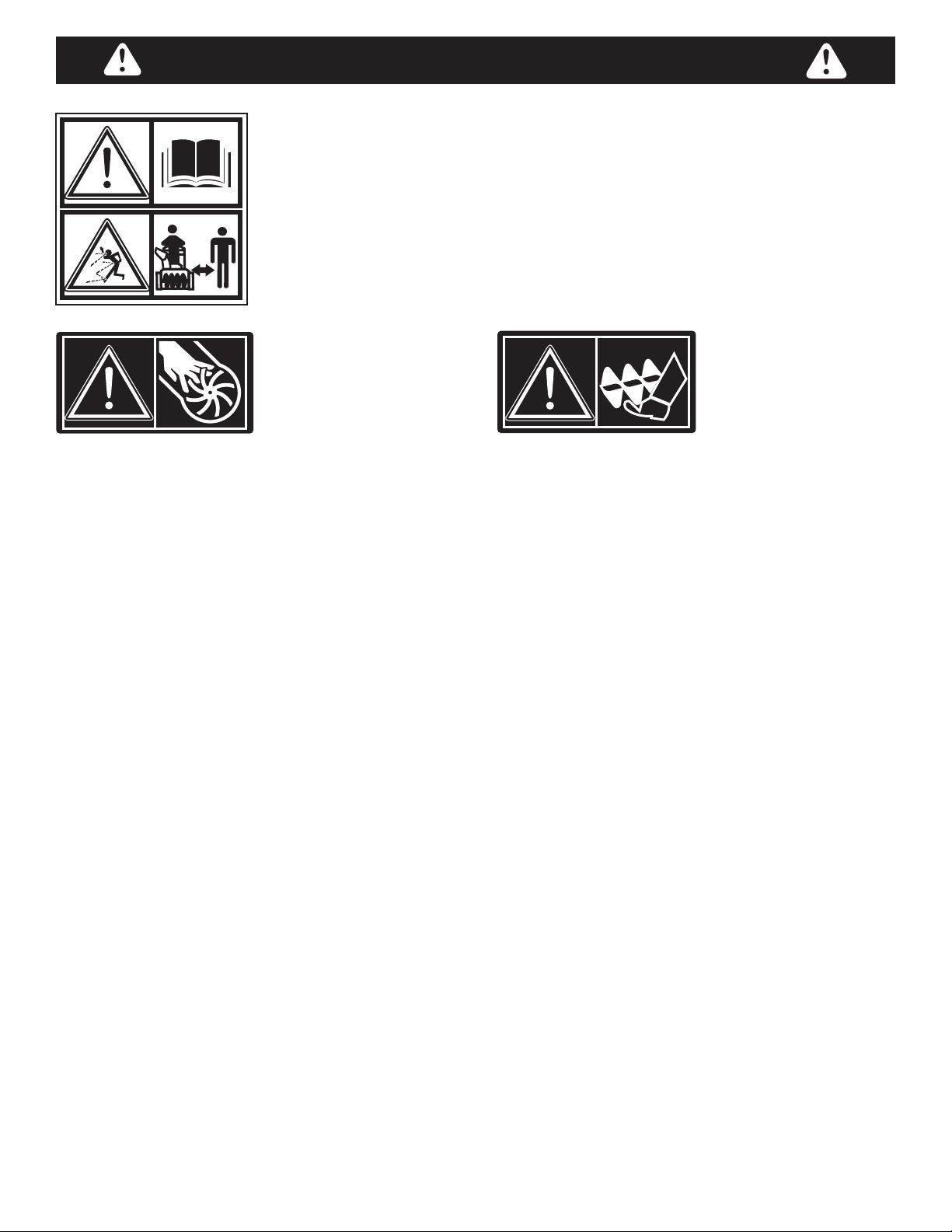
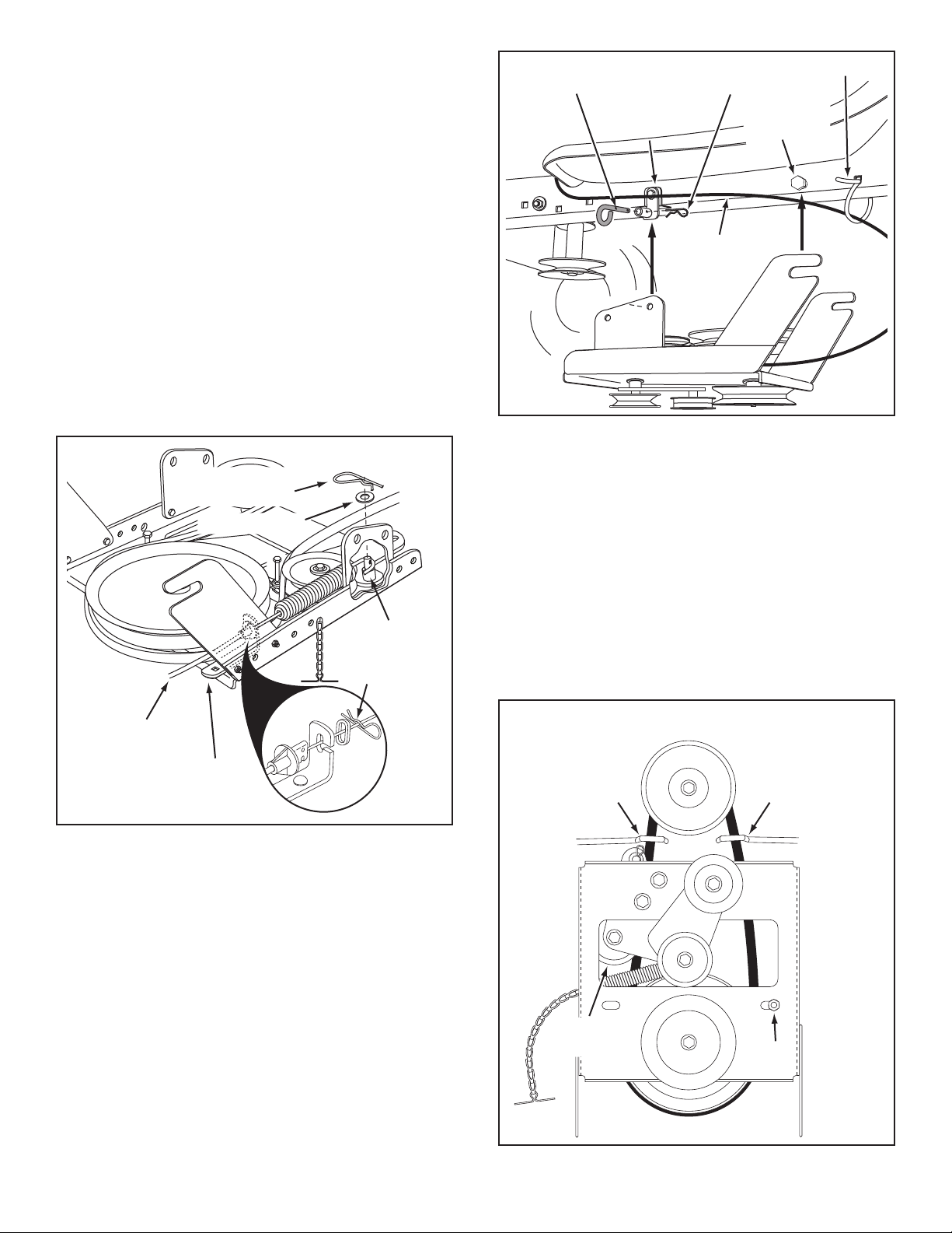
• Neveroperatethesnowthrowerwithoutguards,
plates or other safety protection devices in place.
• Neveroperatethesnowthrowernearglass
enclosures,automobiles,windowwells,dropoffs
etc.withoutproperadjustmentofthesnowthrower
discharge angle.
• Neverrunthesnowthrowerintosnowathighspeeds.
• Donotoverloadthesnowthrowercapacityby
attemptingtoclearsnowattoofastarate.
• Neveroperatethesnowthrowerathightransport
speedonslipperysurfaces.Lookbehindandusecare
whenbackingup.
• Watchfortrafficandstayalertwhencrossingor
operating near roadways.
• Disengagepowertothesnowthrowerwhen
transporting or when not in use.
• Useonlyattachmentsandaccessoriesapprovedby
themanufacturerofthesnowthrower(suchaswheel
weights,counterweights,cabsetc.)
• Neveroperatethesnowthrowerwithoutgoodvisibility.
184045
199683199682

4
HARDWARE PACKAGE CONTENTS
F
BE
H
IJL
P
G
X
V
Y
D
C
W
M
R
S,T
U
Z
O
NOT SHOWN ACTUAL SIZE
SHOWN ACTUAL SIZE
N
K
Q
A
46938
43084
43182
43661
47631
47630
43350 44215
43682
44326
43080
48106
42849
43003 43088 43081
R19172410
47605, 43070 44695
43082
47810
47572
46584
47598
43063
AA
GG
EE
DD
CC
BB
FF
LL
HH
II
JJ KK
46959 27809 27810 42848 HA3090
43343 43055 43038
46963
726-0178
47788 HA9822 42991
23727
MM NN

5
REF. QTY. DESCRIPTION
A 1 Hex Bolt, 3/8" x 3-1/4"
B 2 Hex Bolt, 5/16" x 1-3/4"
C 4 Hex Bolt, 5/16" x 1"
D 4 Hex Bolt, 5/16" x 3/4"
E 6 Hex Bolt, 1/4" x 1"
F 6 HexBolt,3/8"x1"(ThreadForming)
G 2 HexBolt,5/16"x3/4"(ThreadForming)
H 6 Carriage Bolt, 3/8" x 1"
I 2 Carriage Bolt, 5/16" x 1-3/4"
J 2 Carriage Bolt , 5/16" x 1-1/4"
K 4 Carriage Bolt, 5/16" x 1"
L 2 Carriage Bolt, 5/16" x 3/4"
M 4 Shoulder Bolt
N 2 Shear Bolt (spare parts)
O 7 LockWasher,3/8"
P 7 Washer, 1/4"
Q 22 Washer, 5/16" (Extra washers included)
R 8 Washer, 1/2"
S 1 Washer, 3/8" (Thin)
T 3 Washer, 3/8"
REF. QTY. DESCRIPTION
U 2 Bowed Washer
V 6 Flanged Nut, 1/4"
W 1 Flanged Nut, 5/16"
X10 Flanged Nut, 3/8"
Y 22 NylockNut,5/16"(2spareparts)
Z 2 HexLockNut,3/8"
AA 1 Spring
BB 3 Chute Keeper
CC 3 Chute Spacer
DD 1 Trunnion
EE 2 Hairpin Cotter, 5/64"
FF 4 Hairpin Cotter, 1/8"
GG 2 Hairpin Cotter, 3/32"
HH 2 LockPin
II 1 SmallSpacer
JJ 2 Chain, Tensioning
KK 2 TailReector
LL 2 Nylon Tie
MM 1 Grip
NN 1 Plug

6
CARTON CONTENTS
1. HousingAssembly
2. LiftHandleandCable
3. CrankRodSupportTube
4. ChuteCrankRodAssembly
5. EngagementRod(Notusedonsomemodels)
6. CableBracket
7. EnginePulleyKeeper(Notusedonsomemodels)
8. ChuteandControlCableAssembly
9. ClutchIdlerAssembly
10. RearPulleyFrameBracket(2)
11. Anti-rotationBracket.
12. FrontPulleyFrameBracket(2)
13. V-Belt, Drive 56" (#48138)
14. V-Belt, Drive 55" (#46989)
15. V-Belt,Auger(AttachedtoHousingAssembly)
16. L.H.HangerBracket(OutsideMounting)
17. R.H.HangerBracket(OutsideMounting)
18. L.H.HangerBracket(InsideMounting)
19. R.H.HangerBracket(InsideMounting)
20. Left Hand Side Plate
21. Right Hand Side Plate
22. Pulley
23. Large Spacer, 3/8"
46989
48138
42992
11
5
7
17
2
4
6
19
18
16
8
15
13
1
9
3
20 21
14
25678
25679
27509
64452
64451
65450
65367
47043
46948
25728
24558
10
12
27016
48883 25780
22 23

7
• Removeallpartsandhardwarepackagesfromthe
carton. Lay out parts and hardware and identify using
the illustrations on pages 4 and 6.
NOTE: Not all of the supplied parts and hardware will
beneededforyourparticulartractor.Unneededitems
maybediscardedafteryouhavecompletedassembly
andcheckedoperationofunit.DO NOT DISCARD the
twospareshearboltsand5/16"nylocknuts.Refertothe
ServiceandAdjustmentssectiononpage27.
REMOVAL OF PARTS FROM CARTON
TOOLS REQUIRED FOR ASSEMBLY
(2) 7/16" Wrenches
(2) 1/2" Wrenches
(2) 9/16" Wrenches
(2) 3/4" Wrenches
(1) Knife
ADDITIONAL ITEMS REQUIRED
General Purpose Grease
TRACTOR PREPARATION
Beforeperformingtheseinstructions,refertotheService
andAdjustmentssectionofyourtractorowner'smanual
for specic safety instructions.
• Allowengine,mufflerandexhaustdeectortocool
beforebeginning.
• Removeanyfrontorrearattachmentwhichis
mountedtoyourtractor.
•Removethemowerdeck.Refertoyourtractorowner's
manualforremovalinstructions.Markalllooseparts
andsaveforreassembly.
• Removethetractorhood.Refertoyourtractorowner's
manualforremovalinstructions.
FIGURE 2 RIGHT SIDE VIEW
IMPORTANT: Right hand (R.H.) and left hand (L.H.) side
ofthetractoraredeterminedfromtheoperatorsposition
while seated on the tractor.
REMOVE
FRONT SCREWS
REMOVE
BROWNING SHIELD
MOWER DECK
SUSPENSION
BRACKET
FIGURE 1
INSTRUCTIONS FOR TRACTORS WITH
SINGLE FRONT DECK SUSPENSION
BRACKET
STEP 2: (SEE FIGURE 2)
• Removethebrowningshieldfromthefrontofthe
tractorasshown.Holdontotheshieldasyouremove
thesecondscrewtopreventitfromfalling.
• Besuretoreinstallthebrowningshieldwhenso
instructed in step 3.
IDENTIFY YOU TRACTOR
STEP 1: (SEE FIGURE 1)
• Lookunderthefrontofyourtractor.Ifthereisasingle
mowerdecksuspensionbracketlocatedunderneath
themiddleofthefrontaxle,continueontostep
2. If your tractor does not have a mower deck
suspension bracket underneath the middle of the
front axle, skip to step 21 on page 13 for tractors
withdualsuspensionbrackets.
ASSEMBLY
CAUTION: Before starting to assemble the
snowthrower,removethesparkplugwire(s),
settheparkingbrakeandremovethekeyfrom
the tractor ignition.
CAUTION: Do not beginassemblinguntil
thetractorengine,mufflerandexhaust
deectorhavebeenallowedtocooloff.

8
STEP 4: (SEE FIGURE 4)
•Installashoulderbolt,a3/8"washeranda3/8"
angedlocknutintheR.H.andL.H.SidePlates.
FIGURE 4 RIGHT SIDE VIEW
FIGURE 3 RIGHT SIDE VIEW
5/16"
NYLOCK
NUT
5/16" x 1"
CARRIAGE BOLT ENGINE MOUNTING
PLATE
(4) 1/2" WASHERS
(3) 3/8" FLANGE NUTS
(3) 3/8" x 1"
CARRIAGE
BOLTS
SEE NOTE
INSTALL SIDE PLATES
STEP 3: (SEE FIGURE 3)
• FastentheR.H.SidePlate(bendfacingout)tothe
frontthreeholesinthetractorframeusingthree3/8"
x1"carriagebolts,three1/2"washers(seenote)and
three3/8"angenuts. For the rear hole, use a 5/16" x
1"carriagebolt,a1/2"washeranda5/16"nylocknut.
Placethe1/2"washersbetweenthetractorframeand
the side plate. Repeat for L.H. side plate.
• Reinstallthebrowningshieldontothetractorframe
using the original screws.
NOTE:Ifthereisanenginemountingplate(shownwith
dottedlines)leavethe1/2washerofftheboltthatgoes
through the plate.
INSTALL HANGER BRACKETS AND SHOULDER
BOLTS TO OUTSIDE OF FRAME
STEP 5: (SEE FIGURE 5)
•Removethebolt,ifpresent,intheholedirectlybehind
thebrakerodontheleftsideofthetractorframe.
• AttachtheL.H.HangerBracket(tubefacingout)tothe
holeusinga5/16"x3/4"selfthreadingbolt.
• Installashoulderboltintotheholethatis9-1/2"tothe
rearoftheboltyoujustinstalled.Secureitwitha3/8"
angenutontheinsideoftheframe.
FIGURE 5 LEFT SIDE VIEW
5/16" x 3/4" SELF
THREADING BOLT
L.H. HANGER
BRACKET
BRAKE ROD
3/8" FLANGED NUT
SHOULDER
BOLT
5/16" x 3/4" SELF
THREADING BOLT
R.H. HANGER
BRACKET
RIGHT END OF
BRAKE ROD
3/8" FLANGED
NUT
SHOULDER
BOLT
STEP 6: (SEE FIGURE 6)
•Removethebracket,ifpresent,fromtheholedirectly
behindtheendofthebrakerodontherightsideof
thetractorframe.Storethebracketandbolt.
• AttachtheR.H.HangerBrackettotheholeusinga
5/16"x3/4"selfthreadingbolt.
• Installashoulderboltintotheholethatis9-1/2"tothe
rearoftheboltyoujustinstalled.Secureitwitha3/8"
angenutontheinsideoftheframe.
FIGURE 6 RIGHT SIDE VIEW
3/8" WASHER
SHOULDER
BOLT
3/8" FLANGED
NUT

9
STEP 7: (SEE FIGURE 7)
• Attachthecablebrackettothedoubleholeinthe
clutchframeasshown,usinga5/16"x3/4"carriage
boltanda5/16"nylocknut.Placetheboltinthefront
holeofthebracketandintheendoftheholeclosest
to the pulley. Do not tighten yet.
FIGURE 7
FIGURE 9
STEP 9: (SEE FIGURE 9)
• Attacheachrearpulleyframebrackettotheinside
oftheclutchframeusingtwo5/16"x3/4"hexbolts,
5/16"washersand5/16"nylocknuts.
• Attacheachfrontpulleyframebrackettotheinsideof
theclutchframeusingtwo5/16"x1"hexbolts,four
5/16"washersandtwo5/16"nylocknuts.
THIS SECTION IS FOR TRACTORS WITH A
MANUAL ATTACHMENT CLUTCH
If your tractor has an electric attachment clutch go to
step 14 on page 11.
FIGURE 10
STOP
Didyouselectthecorrectdrivebeltforyour
tractor?Usingthewronglengthbeltmay
causeprematurebearingorbeltfailure.
STEP 10: (SEE FIGURE 10)
• Twodifferentlengthdrivebeltsareincludedwithyour
snowthrower.Usethelonger,56"drivebelt(#48138)
ontractorswithmanualattachmentclutches.
• Slightlyloosenthehexboltnexttotheatidlerpulley.
Installthedrivebeltdownbetweenthehexboltandthe
atidlerpulleywiththeatsideofthebeltagainstthe
pulley.Retightenthehexbolt.
• Loopthebeltaroundthelargev-pulley,placingit
betweenthev-pulleyandthehexboltnexttothepulley.
Placethebelttotheinsideoftheotheratidlerpulley.
FIGURE 8
STEP 8: (SEE FIGURE 8)
• Attachthepulley(longendofhubfacingdown)and
thelarge3/8"spacertotheclutchframe.Usea3/8"x
3-1/4"hexbolt,a3/8"washer,a3/8"lockwasheranda
3/8"hexlocknut.
• Installatensioningchainthroughtheholeshownand
theninserta3/32"hairpincotterintothe4thlink.
• Attachthechaintothespringontheloweridlerarm.
CABLE
BRACKET
5/16" x 3/4"
CARRIAGE BOLT
5/16" NYLOCK
NUT
5/16" x 1"
HEX BOLT
5/16" x 3/4"
HEX BOLT 5/16"
NYLOCK
NUT
5/16" WASHER
(2) 5/16"
WASHERS
HEX BOLTS
(#48138)
DRIVE BELT
FLAT IDLER
PULLEYS
LARGE 3/8" SPACER
3/8" LOCKWASHER
3/8" HEX LOCK NUT
3/8" WASHER
3/8" x 3-1/4"
HEX BOLT
TENSIONING
CHAIN
PULLEY
(long end of
hub down)
3/32" HAIRPIN COTTER
IN 4TH LINK

10
FIGURE 12 VIEWED FROM LEFT SIDE
STEP 13: (SEE FIGURE 13)
• Assemblethedrivebeltontotheenginepulleyrst
and then onto the large pulley on top of the clutch/idler
assembly.Thebeltmustbeplacedinsidetheengine
pulleybeltkeeper(s)andbetweenthelargepulleyand
thekeeperboltnexttoit.
IMPORTANT: Do Notassemblethe"V"beltoutsideof
theenginepulleykeepersoroutsideofthekeeperbolt
next to the large pulley.
• Go to step 48 on page 21.
FIGURE 13 VIEWED FROM UNDERNEATH
CLUTCH/IDLER ASSEMBLY
FIGURE 11
ATTACH CLUTCH IDLER ASSEMBLY TO TRACTOR
STEP 12: (SEE FIGURE 12)
• Hooktherearoftheclutch/idlerassemblyontothe
twoshoulderboltsassembledtothetractorframe.
LiftthefrontoftheassemblyandattachittotheR.H.
andL.H.hangerbracketsusingtwolockpinsand1/8"
hairpin cotters.
• Looselyattachthemowerclutchcabletotheleftside
ofthetractorframewithanylontie.Do not pull the
nylontiecompletelytight.Thecablemayneedtobe
removedfromthenylontiewhenusingthemower
deck.
STEP 11: (SEE FIGURE 11)
• Findthecableclipthatisattachedtotheleftside
ofthetractorframeunderneaththefootrest.Open
theclipandremovethemowerclutchcable.Do not
removetheclipfromthetractorframe.Thecable
reattachestotheclipwhenusingthemowerdeck.
• Movetheattachmentclutchleveronthedashpanelto
the disengaged position.
• Placetheclutch/idlerassemblyontheoorontheleft
side of the tractor.
• Attachthetractor'smowerclutchcabletothecable
bracketontheclutch/idlerassembly.Securethecable
housingguide(groovedown)tothecablebracket
using the original collar and a 5/64" hair cotter pin.
• Placethesmallspacerontheweldedpinontheidler
arm.Hooktheendoftheclutchcablespringoverthe
pin and secure it with a 1/4" washer and a 5/64" hair
cotter pin.
• Aligncablebracketwithweldedpinandtightenthe
nutassembledinstep7.
PIVOT LOCK PIN
(use this hole)
SHOULDER
BOLT
L.H. HANGER
BRACKET
1/8" HAIRPIN
COTTER
NYLON TIE
MOWER
CLUTCH
CABLE
5/64" HAIR
COTTER PIN
1/4" WASHER
1/4" SPACER
5/64" HAIR
COTTER PIN
TRACTOR'S
CLUTCH CABLE
CABLE
BRACKET ENGINE
PULLEY
ENGINE
PULLEY
Left Side
of Tractor
ENGINE
PULLEY
KEEPER
ENGINE
PULLEY
KEEPER
KEEPER BOLT
IDLER
PULLEY

11
THIS SECTION IS FOR TRACTORS WITH AN
ELECTRIC ATTACHMENT CLUTCH
STEP 14: (SEE FIGURE 14)
• Turntheclutchidlerassemblyupsidedown.
• Hookthelongendofthespringontotheendofthe
boltthatextendsthroughthenutonthebottomofthe
upperidlerarm.Installa3/8"hexlocknutontothe
bolt,leavingenoughspaceforthespringtopivot.
FIGURE 14
FIGURE 16
STEP 16: (SEE FIGURE 16)
• Attacheachrearpulleyframebrackettotheinsideof
theclutch/idlerassemblyusingtwo5/16"x3/4"hex
bolts,5/16"washersand5/16"nylocknuts.
• Attacheachfrontpulleyframebrackettotheinside
oftheclutch/idlerassemblyusingtwo5/16"x1"hex
bolts,four5/16"washersandtwo5/16"nylocknuts.
STEP 15: (SEE FIGURE 15)
• Inserttensioningchainsthroughtheholesshownand
attachtothespringsontheupperandloweridlerarms.
• Installa3/32"hairpincotterinthe5thlinkofthechain
attachedtotheupperidlerarm.
• Installa3/32"hairpincotterinthe4thlinkofthechain
attachedtotheloweridlerarm.
FIGURE 15
STEP 17: (SEE TABLE 1)
•Twodifferentlengthdrivebeltsareincludedwith
yoursnowthrower.Usethetablebelowtoselect
thecorrectdrivebeltforyourtypetractor.Thepart
numberisprintedontheoutsideofthebelt.
• Setasidethebeltthatisnotforyourtractortoavoid
accidentally using it.
SELECT THE CORRECT DRIVE BELT
(Electric clutch tractors with a single front deck
suspension bracket)
55" BELT (PART #46989)
TRACTOR TYPE DECK SIZE CLUTCH TYPE
(LT) Lawn Tractor 38", 42" Electric
56" BELT (PART #48138)
TRACTOR TYPE DECK SIZE CLUTCH TYPE
(LT) Lawn Tractor 48" Electric
(GT) Garden Tractor 48", 54" Electric
TABLE 1
3/8" HEX
LOCK NUT
SPRING
ATTACH
LONG
END OF
SPRING
HERE
TENSIONING CHAIN
(lower idler arm)
TENSIONING CHAIN
(upper idler arm)
3/32" HAIRPIN
COTTER IN
5th LINK
3/32" HAIRPIN COTTER
IN 4th LINK
5/16" x 1" HEX BOLT
5/16" x 3/4"
HEX BOLT
5/16" NYLOCK NUT
5/16" WASHER
5/16"
NYLOCK NUT
(2) 5/16" WASHERS

12
STEP 19: (SEE FIGURE 18)
• Hooktherearoftheclutch/idlerassemblyontothe
twoshoulderboltsassembledtotheoutsideofthe
tractorframe.Liftthefrontoftheassemblyandattach
ittotheR.H.andL.H.hangerbracketsusingtwopivot
lockpinsand1/8"hairpincotters.
FIGURE 18 VIEWED FROM LEFT SIDE
FIGURE 19 VIEWED FROM UNDERNEATH
FIGURE 17
STEP 18: (SEE FIGURE 17)
• Turntheclutch/idlerassemblyrightsideup.
• Slightlyloosenthehexboltnexttotheatidlerpulley.
Installthedrivebeltdownbetweenthehexboltandthe
atidlerpulleywiththeatsideofthebeltagainstthe
pulley.Retightenthehexbolt.
• Loopthebeltaroundthelargev-pulley,placingit
betweenthev-pulleyandthehexboltnexttothepulley.
STOP
Didyouchoosethecorrectdrivebeltfor
yourtractor?Usingthewronglengthbelt
maycauseprematurebearingorbeltfailure.
DRIVE BELT
FLAT IDLER
PULLEY
HEX BOLTS
PIVOT LOCK PIN
(use second hole)
SHOULDER
BOLT
1/8" HAIRPIN
COTTER
L.H. HANGER
BRACKET
1/8"
HAIRPIN
COTTER
ENGINE
PULLEY
HEX BOLTS
FLAT IDLER
PULLEY
TENSIONING
CHAIN
LEFT SIDE
OF TRACTOR
STEP 20: (SEE FIGURE 19)
• Assemblethedrivebeltontotheenginepulley.You
mayneedtoremovethebeltfromthelargepulleyon
theclutch/idlerassemblyinordertoassembleitonto
theenginepulley.Whenre-assemblingthebeltonto
thelargepulley,besurethebeltisbetweenthelarge
pulleyandthehexboltnexttoit.
• Placetensiononthebeltbypullingtheleftside
tensioning chain out as far as the 3/32" hairpin cotter
that was installed in the chain in step 15 will allow.
Securethechaininthispositionbyinsertinga1/8"
hairpin cotter through the chain.
NOTE;Topreventthechainfromdraggingonthe
ground,looptheendofthechainthoughthepivotlock
pin. Refer to gure 56 on page 23.
• Go to step 48 on page 21.

13
STEP 22: (SEE FIGURE 21)
• FastentheR.H.SidePlate(bendfacingout)tothe
frontthreeholesshowninthetractorframeusing
three3/8"x1"threadformingbolts,three3/8"lock
washers and one 1/2" washer. Place the washer on
thethirdboltasashimbetweenthesideplateand
theframe.Tightenallbolts.RepeatfortheL.H.side.
NOTE:Ifyouinstalledaboltinthefourthholeinstep21,
assemblea5/16"angenutontotheboltaftertheside
plate is installed.
• Go to step 25 on this page.
(3) 3/8" x 1"
THREAD FORMING
BOLTS
5/16" FLANGED
NUT
(SEE NOTE) (3) 3/8" LOCK
WASHERS
1/2" WASHER
5/16" x 1"
CARRIAGE BOLT
(SEE NOTE)
FIGURE 21 RIGHT SIDE VIEW
FRONT SUSPENSION
BRACKET
REMOVE BOLTS
IF PRESENT
FIGURE 22 RIGHT SIDE VIEW
STEP 23: (SEE FIGURE 22)
•Removeanyboltsfoundintheholesshown.
STEP 21: (SEE FIGURE 20)
•Removeboltsfromfrontthreeholesshown.
• Ifaboltispresentinthefourthhole,replaceitwith
a5/16"x1"carriageboltwithoutanut.Thebracket
fastenedtoinsideofframemustremaininplace.
FRONT
SUSPENSION
BRACKET
REPLACE BOLT
(IF PRESENT)
REMOVE BOLTS
(IF PRESENT)
FIGURE 20 RIGHT SIDE VIEW
INSTRUCTIONS FOR TRACTORS WITH DUAL
FRONT DECK SUSPENSION BRACKETS
FASTEN SIDE PLATES TO TRACTOR
Ifyourtractorresemblesgure20,startwithstep21.
Ifyourtractorresemblesgure22,startwithstep23.
STEP 25: (SEE FIGURE 24)
•Installahexheadshoulderbolt,a3/8"washeranda
3/8"angedlocknutintheR.H.andL.H.SidePlates.
FIGURE 24 RIGHT SIDE VIEW
3/8" WASHER
SHOULDER
BOLT 3/8" FLANGED
NUT
STEP 24: (SEE FIGURE 23)
•FastentheR.H.SidePlate(bendfacingout)tothe
threeholesshowninthetractorframe.Usethree3/8"
x1"threadformingbolts,3/8"lockwashersand1/2"
washers.Usethe1/2"washersasshimsbetweenthe
SidePlateandthetractorframe.Tightenallboltsand
repeat for the L.H. side.
NOTE:Iftheboltinsertsfreelyintothefronthole,assemble
a3/8"angednutontothebolt.
(3) 3/8" x 1"
THREAD FORMING
BOLTS
(3) 3/8" LOCK
WASHERS
3/8" FLANGED NUT
(SEE NOTE)
(3) 1/2" WASHERS
FIGURE 23 RIGHT SIDE VIEW

14
FIGURE 28 RIGHT SIDE VIEW
INSTALLING HANGER BRACKETS
Forbetterclearance,lowerthetractor'ssuspensionarms
usingtheattachmentliftlever.
STEP 26: (SEE FIGURE 25 or 26)
On Tractors With Foot Rest Brackets
•RemovetheboltandnutthatfastentheL.H.andR.H.
footrestbracketstotheframe.
• AttachtheL.H.HangerBracket(marked"L")tothe
insideofthetractorframeusingtwo3/8"x1"carriage
boltsand3/8"angednuts.Boltheadsgooninsideof
tractorframe.RepeatfortheR.H.side.
FIGURE 26 LEFT SIDE VIEW
FIGURE 25 LEFT SIDE VIEW
On Tractors Without Foot Rest Brackets
• Findtheemptyholebeneaththefootrest.Attachthe
L.H.HangerBracket(marked"L")totheinsideof
theframeusinga3/8"x1"carriageboltanda3/8"
angednut.Boltheadgoesoninsideoftractorframe.
Repeat for the R.H. side.
STEP 28: (SEE FIGURE 28)
• Assembleashoulderboltand3/8"angednuttothe
R.H.sideofthetractorframe,usingtherstempty
holetotherearoftheR.H.hangerbracket.Boltgoes
oninsideofframe.
FIGURE 27 LEFT SIDE VIEW
INSTALLING SHOULDER BOLTS
STEP 27: (SEE FIGURE 27)
• Removethebolt,washerandnutwhichfastenthe
swaybarbrackettotheL.H.sideofthetractorframe.
Replacewithashoulderboltanda3/8"angednut.
Boltgoesoninsideofframe.
BOLT REMOVED
FROM THIS HOLE
SWAY BAR
BRACKET
SHOULDER BOLT
3/8"
FLANGED
NUT
3/8" x 1"
CARRIAGE
BOLT
3/8" FLANGED NUT
L.H. HANGER
BRACKET
SUSPENSION ARM
SHOULDER BOLT
3/8"
FLANGED
NUT
R.H. HANGER BRACKET
BOLT REMOVED
FROM THIS HOLE
3/8" x 1"
CARRIAGE
BOLT
3/8" FLANGED
NUT
L.H. HANGER
BRACKET
SUSPENSION ARM

15
INSTALLING CLUTCH/IDLER ASSEMBLY
This section covers the installation of the Clutch/Idler
assemblytotractorswithattachmentclutchesthatare
eitherrodoperated(p.15),cableoperated(p.17)or
electric (p. 19). Use the appropriate instructions for your
tractor.
ROD OPERATED MANUAL ATTACHMENT CLUTCH
STEP 29: (SEE FIGURE 29)
• Movetheattachmentclutchleveronthedashpanelto
the disengaged (down) position.
• Screwthetrunnionontotheendofthesnowthrower
engagementrod.
• Locatetheclutcharm(wherethemowerclutchrod
was connected) underneath the right hand side the
tractor,justtotheinsideofthesuspensionarm.If
there is an extension attached to the clutch lever, the
extension,boltandnutmustberemovedandstored
withthemowerdeck.
IMPORTANT: Re-attach the extension to the clutch
leverbeforereinstallingthemowerdeck.
• Positiontheengagementrodtotheinsideoftheclutch
armandinsertthedrilledendoftherodthroughthe
arm.Securewitha5/64"hairpincotter.
FIGURE 29 RIGHT SIDE VIEW
ENGAGEMENT ROD
5/64" HAIRPIN
COTTER
TRACTOR'S CLUTCH ARM
SUSPENSION ARM
TRUNNION
REMOVE EXTENSION,
BOLT AND NUT
(IF PRESENT)
STEP 30: (SEE FIGURE 30)
• Attachthetworearpulleyframebracketstotheinside
oftheclutch/idlerassemblyusingtwo5/16"x1"hex
bolts,eight5/16"washersandtwo5/16"nylocknutsfor
eachbracket.
• Attachthetwofrontpulleyframebracketstotheinside
oftheclutch/idlerassemblyusingtwo5/16"x3/4"hex
bolts,5/16"washersand5/16"nylocknutsforeach
bracket.Addextrawashersifneeded.
FIGURE 30
FIGURE 31
STOP
Didyouchoosethecorrectdrivebeltfor
yourtractor?Usingthewronglengthbelt
maycauseprematurebearingorbeltfailure.
STEP 31: (SEE FIGURE 31)
• Twodifferentlengthdrivebeltsareincludedwith
yoursnowthrower.Tractorswithmanualattachment
clutchesanddualfrontdecksuspensionbracketsuse
the55"drivebeltwith#46989 printed on the outside
ofthebelt.DO NOT USEtheotherbelt.
• Slightlyloosenthehexboltnexttotheatidlerpulley.
Installthedrivebeltdownbetweenthehexboltandthe
atidlerpulleywiththeatsideofthebeltagainstthe
pulley.Retightenthehexbolt.
• Loopthebeltaroundthelargev-pulley,placingit
betweenthev-pulleyandthehexboltnexttothepulley.
TENSIONING CHAIN
(lower idler arm)
5/16" x 3/4"
HEX BOLT
5/16" x 1"
HEX BOLT
5/16" NYLOCK NUT
5/16"
WASHER
(4) 5/16" WASHERS
3/32" HAIRPIN
COTTER IN
4th LINK
#46989
DRIVE BELT
FLAT IDLER
PULLEY
HEX BOLTS
• Insertatensioningchainthroughtheholeshownand
attachittothespringontheloweridlerarm.
• Installa3/32"hairpincotterinthe4thlinkofthechain.

16
FIGURE 33 RIGHT SIDE VIEW
FIGURE 32 RIGHT SIDE VIEW
STEP 33: (SEE FIGURE 33)
• Makesuretheattachmentclutchleveronthedash
panel is in the disengaged (down) position.
• Pivottheupperidlerarmsothatitrestsagainst
thestopboltandispointingtowardthefrontas
shown. Screw the trunnion along the threads of the
engagementroduntilitisalignedatthefrontendof
theidlerarmslot.Attachthetrunniontotheslotusing
the 3/8" thin washer and a 5/64" hairpin cotter.
• Removetheenginepulleykeeperfromthesideof
thetractorframebyremovingthewasherandnut
thatsecurethekeeper.Attachthenewpulleykeeper
supplied with the snow thrower, reusing the original
bolt,washerandnut.
NOTE:Sometractorsmayalreadybeequippedwitha
pulleykeeperthatisidenticaltothenewonesupplied.
IDLER ARM
5/64" HAIRPIN
COTTER
TRUNNION
STOP BOLT
3/8" THIN
WASHER
NEW ENGINE PULLEY KEEPER WITH
ORIGINAL BOLT, NUT AND WASHER
STEP 34: (SEE FIGURE 34)
• Assembletheshort"V"beltontotheenginepulley
and then onto the large pulley on top of the clutch/idler
assembly.Thebeltmustbeplacedtotheinsideofthe
enginepulleykeeper,theidlerpulleyandthekeeper
boltlocatedbesidethelargepulley.
IMPORTANT: Do Notassemblethe"V"beltaroundthe
outsideoftheenginepulleykeeperorthekeeperbolt.
• Go to step 48 on page 21.
FIGURE 34 VIEWED FROM UNDERNEATH
CLUTCH/IDLER ASSEMBLY
STEP 32: (SEE FIGURE 32)
• Besuretoliftupthefrontendoftheengagementrod
asshownwhenperformingthenextoperation.You
cantemporarilysupporttherodusingarubberband
tiedtotheenginepulleykeeper.
• Attachtheclutch/idlerassemblytothetractorframe
asfollows.Hooktheassembly'snotchedrearpulley
framebracketsontothetwoshoulderboltsyou
assembledtotheinsideofthetractorframe.Liftthe
frontoftheassemblyandattachittotheR.H.andL.H.
hangerbracketsusingtwopivotlockpinsand1/8"
hairpin cotters.
PIVOT LOCK PIN (MM)
(use second hole)
1/8" HAIRPIN COTTER
ENGAGEMENT
ROD
ENGINE
PULLEY
KEEPER BOLT
IDLER
PULLEY
ENGINE
PULLEY
KEEPER
Left Side
of Tractor

17
FIGURE 36
STEP 35: (SEE FIGURE 35)
• Assemblethecablebrackettoinnerpartofthedouble
holesintheclutch/idlerassemblyusingtwo5/16"x
3/4"carriageboltsand5/16"nylocknuts.Usethetwo
frontholesinthecablebracketfor42"mowerdecks.
Usethetworearholesfor46"mowerdecks.
STEP 36: (SEE FIGURE 36)
• Attachthetworearpulleyframebracketstotheinsideof
theclutch/idlerassemblyusingtwo5/16"x1"hexbolts,
eight5/16"washersandtwo5/16"nylocknutsforeach
bracket.
• Attachthetwofrontpulleyframebracketstotheinside
oftheclutch/idlerassemblyusingtwo5/16"x3/4"hex
bolts,5/16"washersand5/16"nylocknutsforeach
bracket.Addextrawashersifneededinstep39.
• Insertatensioningchainthroughtheholeshownand
attachtheendlinktothespringontheloweridlerarm.
• Installa3/32"hairpincotterinthe4thlinkofthechain.
FIGURE 35
CABLE OPERATED MANUAL ATTACHMENT CLUTCH
FIGURE 37
HEX BOLTS
DRIVE BELT
FLAT IDLER
PULLEY
(#46989)
STEP 37: (SEE FIGURE 37)
• Twodifferentlengthdrivebeltsareincludedwith
yoursnowthrower.Tractorswithmanualattachment
clutchesanddualfrontdecksuspensionbracketsuse
the55"drivebeltwith#46989 printed on the outside
ofthebelt.DO NOT USEtheotherbelt.
• Slightlyloosenthehexboltnexttotheatidlerpulley.
Installthedrivebeltdownbetweenthehexboltandthe
atidlerpulleywiththeatsideofthebeltagainstthe
pulley.Retightenthehexbolt.
• Loopthebeltaroundthelargev-pulley,placingit
betweenthev-pulleyandthehexboltnexttothepulley.
STOP
Didyouchoosethecorrectdrivebeltfor
yourtractor?Usingthewronglengthbelt
maycauseprematurebearingorbeltfailure.
CABLE
BRACKET
5/16" x 3/4"
CARRIAGE BOLT
5/16" NYLOCK
NUT
42"
DECKS
46"
DECKS
TENSIONING CHAIN
(lower idler arm)
5/16" x 3/4"
HEX BOLT
5/16" x 1"
HEX BOLT
5/16" NYLOCK NUT
5/16"
WASHER
(4) 5/16" WASHERS
3/32" HAIRPIN
COTTER IN
4th LINK

18
FIGURE 40 VIEWED FROM UNDERNEATH
FIGURE 39
STEP 40: (SEE FIGURE 40)
• Assembletheshort"V"beltontotheenginepulley
and then onto the large pulley on top of the clutch/idler
assembly.Thebeltmustbeplacedtotheinsideofthe
enginepulleykeeper,theidlerpulleyandthekeeper
boltlocatedbesidethelargepulley.
IMPORTANT: Do Notassemblethe"V"beltaroundthe
outsideoftheenginepulleykeeperorthekeeperbolt.
• Go to step 48 on page 21.
STEP 39: (SEE FIGURE 39)
• Removetheenginepulleykeeperfromthesideof
thetractorframebyremovingthewasherandnut
thatsecurethekeeper.Attachthenewpulleykeeper
supplied with the snow thrower, reusing the original
bolt,washerandnut.
NOTE:Sometractorsmayalreadybeequippedwitha
pulleykeeperthatisidenticaltothenewonesupplied.
• Attachtheclutch/idlerassemblytothetractorframe
asfollows.Hooktherearoftheassemblyontothetwo
shoulderboltsyouinstalledonthetractorframe.Lift
thefrontoftheassemblyandattachittothehanger
bracketsyouinstalledusingtwopivotlockpinsand
1/8" hairpin cotters.
FIGURE 38
STEP 38: (SEE FIGURE 38)
• Movetheattachmentclutchleveronthedashpanelto
the disengaged (down) position.
• Placetheclutch/idlerassemblyontheoorontheright
side of the tractor.
• Attachthetractor'sclutchcabletothecablebracket.
Securethecablehousingguide(groovedown)tothe
cablebracketusingtheoriginalcollaranda5/64"hair
cotter pin.
• Placeaspacerontheweldedpinontheidlerarm.
Hooktheendoftheclutchspringoverthepinand
secure it with a 1/4" washer and a 5/64" hair cotter pin.
5/64" HAIR
COTTER PIN
1/4" WASHER
TRACTOR'S
CLUTCH CABLE
5/64" HAIR
COTTER PIN
SPACER
NEW ENGINE PULLEY KEEPER WITH
ORIGINAL BOLT, NUT AND WASHER
PIVOT LOCK PIN
(use second hole)
1/8" HAIRPIN COTTER
ENGINE
PULLEY
KEEPER BOLT
IDLER
PULLEY
ENGINE
PULLEY
KEEPER
Left Side
of Tractor

19
ELECTRIC ATTACHMENT CLUTCHES
FIGURE 42
FIGURE 43 VIEW OF BOTTOM
STEP 43: (SEE FIGURE 43)
• Attachthetworearpulleyframebracketstotheinside
oftheclutch/idlerassemblyusingtwo5/16"x1"hex
bolts,eight5/16"washersandtwo5/16"nylocknuts
foreachbracket.
• Attachthetwofrontpulleyframebracketstotheinside
oftheclutch/idlerassemblyusingtwo5/16"x3/4"hex
bolts,5/16"washersand5/16"nylocknutsforeach
bracket.
STEP 44: (SEE TABLE 2)
•Twodifferentlengthdrivebeltsareincludedwith
yoursnowthrower.Usethetablebelowtoselect
thecorrectdrivebeltforyourtypetractor.Thepart
numberisprintedontheoutsideofthebelt.
• Setasidethebeltthatisnotforyourtractortoavoid
accidentally using it.
55" BELT (PART #46989)
TRACTOR TYPE DECK SIZE CLUTCH TYPE
56" BELT (PART #48138)
TRACTOR TYPE DECK SIZE CLUTCH TYPE
(LT) Lawn Tractor 48" Electric
(LT) Lawn Tractor 38", 42", 46" Electric
TABLE 2
STEP 41: (SEE FIGURE 41)
• Turntheclutchidlerassemblyupsidedown.
• Hookthelongendofthespringontotheendofthe
boltthatextendsthroughthenutonthebottomofthe
upperidlerarm.Installa3/8"hexlocknutontothebolt,
leaving enough space for the spring to pivot.
FIGURE 41
STEP 42: (SEE FIGURE 42)
• Inserttensioningchainsthroughtheholesshownand
attachtothespringsontheupperandloweridlerarms.
• Installa3/32"hairpincotterinthe5thlinkofthechain
attachedtotheupperidlerarm.
• Installa3/32"hairpincotterinthe4thlinkofthechain
attachedtotheloweridlerarm.
3/8" HEX
LOCK NUT
SPRING
ATTACH
LONG
END OF
SPRING
HERE
TENSIONING CHAIN
(lower idler arm)
TENSIONING CHAIN
(upper idler arm)
3/32" HAIRPIN
COTTER IN
5th LINK
3/32" HAIRPIN COTTER
IN 4th LINK
5/16" x 3/4" HEX BOLT
5/16" x 1"
HEX BOLT
5/16" NYLOCK NUT
5/16"
WASHER
(4) 5/16" WASHERS

20
FIGURE 46 VIEWED FROM UNDERNEATH
STEP 47: (SEE FIGURE 46)
• Assemblethedrivebeltontotheenginepulleyand
then onto the large pulley on top of the clutch/idler
assembly.Thebeltmustbeplacedtotheinsideof
theidlerpulleyandthekeeperboltlocatedbesidethe
large pulley.
• Placetensiononthebeltbypullingtheleftside
tensioning chain out as far as the 3/32" hairpin cotter
willallow.Securethechaininthispositionbyinserting
a 1/8" hairpin cotter through the chain.
IMPORTANT: Do Notassemblethe"V"beltaroundthe
outsideoftheenginepulleykeeperorthekeeperbolt.
STEP 46: (SEE FIGURE 45)
• Attachtheclutch/idlerassemblytothetractorframeas
follows.Hooktheassembly'snotchedarmsontothe
twoshoulderboltsyouassembledtotheinsideofthe
tractorframe.Liftthefrontoftheassemblyandattach
ittotheR.H.andL.H.hangerbracketsusingtwopivot
lockpinsand1/8"hairpincotters.
FIGURE 45 RIGHT SIDE VIEW
CLUTCH/IDLER ASSEMBLY
FIGURE 44
STOP
Didyouchoosethecorrectdrivebeltfor
yourtractor?Usingthewronglengthbelt
maycauseprematurebearingorbeltfailure.
STEP 45: (SEE FIGURE 44)
• Turntheclutch/idlerassemblyrightsideup.
• Slightlyloosenthehexboltnexttotheatidlerpulley.
Installthedrivebeltdownbetweenthehexboltandthe
atidlerpulleywiththeatsideofthebeltagainstthe
pulley.Retightenthehexbolt.
• Loopthebeltaroundthelargev-pulley,placingit
betweenthev-pulleyandthehexboltnexttothepulley.
DRIVE BELT
FLAT IDLER
PULLEY
HEX BOLTS
PIVOT LOCK PIN
(use second hole)
1/8" HAIRPIN COTTER
1/8" HAIRPIN
COTTER
ENGINE
PULLEY
ENGINE
PULLEY
Left Side
of Tractor
KEEPER
BOLT
IDLER
PULLEY
Table of contents
Other Agri-Fab Snow Blower manuals

Agri-Fab
Agri-Fab LST42B User manual

Agri-Fab
Agri-Fab LST42D User manual

Agri-Fab
Agri-Fab 45-0418 User manual

Agri-Fab
Agri-Fab LST 42A User manual

Agri-Fab
Agri-Fab HUSQVARNA 966 41 60-01 User manual

Agri-Fab
Agri-Fab 45-0418 Use and care manual

Agri-Fab
Agri-Fab 45-0491 User manual

Agri-Fab
Agri-Fab 45-0491 User manual

Agri-Fab
Agri-Fab 45-0418 User manual

Agri-Fab
Agri-Fab LST42E User manual