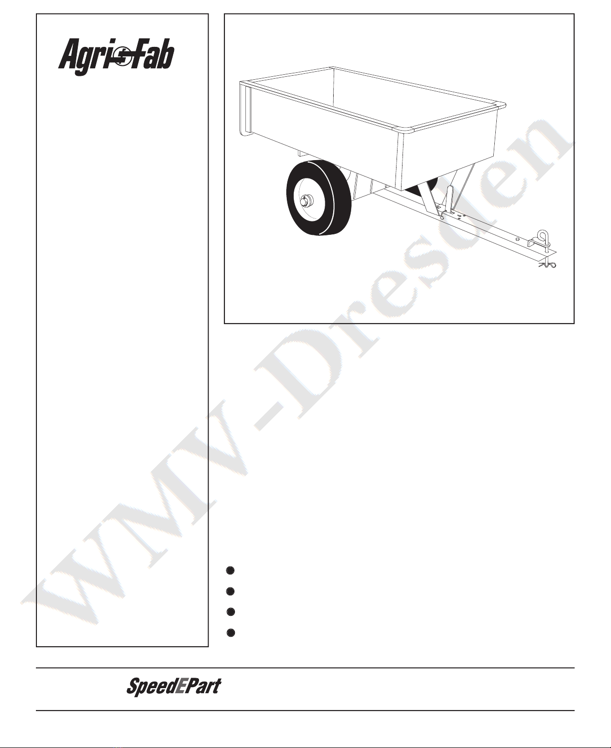
REPAIR PARTS LIST FOR 45-01003 UTILITY CART
3 62458 1 Tailgate Reinforcement Bracket
3 62458 1 Tailgate Reinforcement Bracket
3 62458 1 Tailgate Reinforcement Bracket
4 23548 2 Guide, Tailgate
4 23548 2 Guide, Tailgate
4 23548 2 Guide, Tailgate
7 24497 1 Latch Stand Bracket
7 24497 1 Latch Stand Bracket
7 24497 1 Latch Stand Bracket
8 24498 1 Latch Lock Lever
8 24498 1 Latch Lock Lever
8 24498 1 Latch Lock Lever
10 24499 1 Draw Bar Tongue
10 24499 1 Draw Bar Tongue
10 24499 1 Draw Bar Tongue
11 24896 1 Axle, Wheel 3/4" Dia.
11 24896 1 Axle, Wheel 3/4" Dia.
11 24896 1 Axle, Wheel 3/4" Dia.
12 23484 2 Cap, Front Corner
12 23484 2 Cap, Front Corner
12 23484 2 Cap, Front Corner
14 43010 2 Cotter Pin, 1/8" Dia. x 1" *
14 43010 2 Cotter Pin, 1/8" Dia. x 1" *
14 43010 2 Cotter Pin, 1/8" Dia. x 1" *
15 43009 4 Washer, Flat 3/4" *
15 43009 4 Washer, Flat 3/4" *
15 43009 4 Washer, Flat 3/4" *
16 47407 1 Hex Bolt, 5/16-18 x 3-3/4"
16 47407 1 Hex Bolt, 5/16-18 x 3-3/4"
16 47407 1 Hex Bolt, 5/16-18 x 3-3/4"
17 47810 13 Nylock Nut, 5/16-18 Thread*
17 47810 13 Nylock Nut, 5/16-18 Thread*
17 47810 13 Nylock Nut, 5/16-18 Thread*
18 43866 20 Hex Bolt, 1/4-20 x 5/8" *
18 43866 20 Hex Bolt, 1/4-20 x 5/8" *
18 43866 20 Hex Bolt, 1/4-20 x 5/8" *
19 47189 20 Nylock Nut, 1/4-20 Thread
19 47189 20 Nylock Nut, 1/4-20 Thread
19 47189 20 Nylock Nut, 1/4-20 Thread
20 43814 12 Slt. Truss Hd. Bolt, 5/16-18 x 3/4" Lg.*
20 43814 12 Slt. Truss Hd. Bolt, 5/16-18 x 3/4" Lg.*
20 43814 12 Slt. Truss Hd. Bolt, 5/16-18 x 3/4" Lg.*
21 46980 2 Hex Nut, 5/16-18 Thread (SEMS)
21 46980 2 Hex Nut, 5/16-18 Thread (SEMS)
21 46980 2 Hex Nut, 5/16-18 Thread (SEMS)
22 43001 1 Hex Bolt, 3/8-16 x 1" Lg. *
22 43001 1 Hex Bolt, 3/8-16 x 1" Lg. *
22 43001 1 Hex Bolt, 3/8-16 x 1" Lg. *
24 HA21362 1 Nylock Nut, 3/8-16 Thread *
24 HA21362 1 Nylock Nut, 3/8-16 Thread *
24 HA21362 1 Nylock Nut, 3/8-16 Thread *
25 47408 1 Extension Spring
25 47408 1 Extension Spring
25 47408 1 Extension Spring
26 47622 1 Spring Puller Tool
26 47622 1 Spring Puller Tool
26 47622 1 Spring Puller Tool
28 43343 1 Hair Cotter Pin, 1/8" (#4) *
28 43343 1 Hair Cotter Pin, 1/8" (#4) *
28 43343 1 Hair Cotter Pin, 1/8" (#4) *
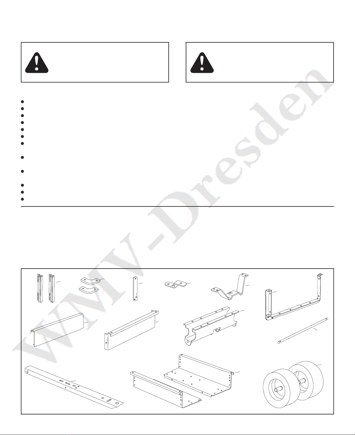
3 62458 1 Tailgate Reinforcement Bracket
4 23548 2 Guide, Tailgate
7 24497 1 Latch Stand Bracket
8 24498 1 Latch Lock Lever
10 24499 1 Draw Bar Tongue
11 24896 1 Axle, Wheel 3/4" Dia.
12 23484 2 Cap, Front Corner
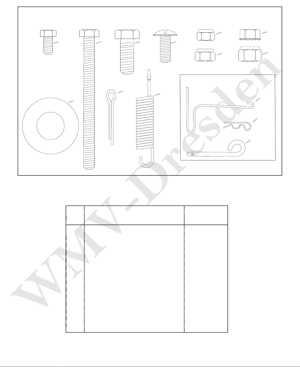
14 43010 2 Cotter Pin, 1/8" Dia. x 1" *
15 43009 4 Washer, Flat 3/4" *
16 47407 1 Hex Bolt, 5/16-18 x 3-3/4"
17 47810 13 Nylock Nut, 5/16-18 Thread*
18 43866 20 Hex Bolt, 1/4-20 x 5/8" *
19 47189 20 Nylock Nut, 1/4-20 Thread
20 43814 12 Slt. Truss Hd. Bolt, 5/16-18 x 3/4" Lg.*
21 46980 2 Hex Nut, 5/16-18 Thread (SEMS)
22 43001 1 Hex Bolt, 3/8-16 x 1" Lg. *
24 HA21362 1 Nylock Nut, 3/8-16 Thread *
25 47408 1 Extension Spring
26 47622 1 Spring Puller Tool
28 43343 1 Hair Cotter Pin, 1/8" (#4) *
* Purchase Common Hardware Locally
the fastest way to purchase parts
www.speedepart.com