AHCON BBRT 700 User manual

OPERATOR’s MANUAL
BBRT 700 / 900

2
INDEX
Page
Manufacturer’s Information 3
Warnings 4
Risks and Labelling 5
Safety Precautions 6
Warranty 7
Dimensions and Weight 8
Shipping Dimensions 8
Transport and Handling 9
Unpacking 9
Connection of the Machine 10
Operation 11-13
Noise 14
Special Functions and Accessories 14
Standards for Built-in Parts 14
Maintenance 15
Repair 15
Charts 16
Declaration of Conformity and CE-labelling 17

3
Manufacturer’s Information
Art. No.: 610 12 100 / 610 12 140
Type: AHCON BBRT 700 / 900 Bead Breaker
Use: Semi-automatic Bead Breaker for passenger, van and light truck
tyres.
Max. tyre diameter: 950 mm
Max. width of rim: 12“
Field Operation: To be used as an independent Bead Breaker or as a built-in part
of an AHCON Speed Line System.
Manufacturer: AHCON WHEEL SERVICE EQUIPMENT
Danmarksvej 25
DK - 8660 Skanderborg
+45 76152150
Distributor:

4
WARNINGS !
Safety Precautions
AHCON BBRT 700 / 900 must only be used by trained personnel.
AHCON BBRT 700 / 900 must only be used for bead breaking of passenger tyres, van
tyres and light truck tyres.
Tyre service should only be performed by persons trained properly.
AHCON disclaim all responsibility for failures occurring by working procedures, which do
not comply with procedures recommended by AHCON and /or tyre and rim manufacturers
(STRO).

5
Risks and Labelling
Danger of Squeezing!
Pictograms and warning labels placed on the machine by the manufacturer must
not be removed!
If warning labels are removed the responsibility of the manufacturer will be
renounced.

6
Safety Precautions
Safety Distance
None for the operator.
1 meter for the outsider.
No special precautions are needed.
Safety Devices
The control valve for the cylinder is equipped with a return spring.
A protection shield is built-in above the foot pedal to secure that the operator does not
activate the bead breaker by mistake.
The machine is constructed in such a way that the operator cannot be harmed by normal
use of the machine as long as the instructions are closely followed.

7
Warranty
AHCON guarantees that the product will live up to the specifications at the time of delivery
and will be faultless as regards materials and workmanship for a period of 12 months after
the product has been invoiced to the end user.
Components and parts related to normal wear and tear are not included in the warranty.
AHCON will not be responsible for damages occurring by negligence, improper use,
incorrect installation, etc.
All products and parts returned to AHCON for repair and replacement must be forwarded
carriage paid.

8
Dimensions and Weight
Shipping Dimensions
Height: 1350 mm Weight: 157 kg
Length: 1200 mm
Width: 800 mm Shipping weight: 170 kg

9
Transport and Handling
This machine has to be transported with a pallet stacker or a fork-lift truck according to the
below instructions.
Place the machine close to the place of use.
Remove the bolts holding the machine to the pallet.
Unpacking
Remove the wrap folio and cut the tape holding the Bead Breaker’s arm down.
Check that the contents correspond to the order.
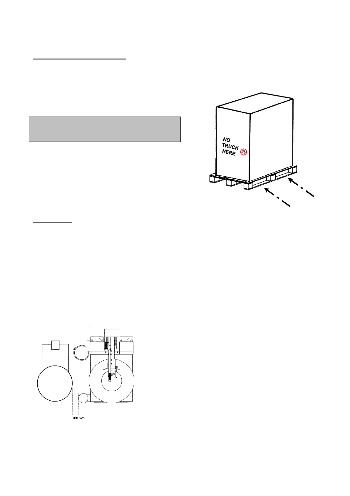
Place the machine on an even floor at a distance of approx. 100 mm from the wheel
turning plate and the Bead Breaker’s rotation plate. Please see the below illustration.
If the Bead Breaker is equipped with a wheel turning plate with swinging support arm the
distance should be approx. 400 mm.
Tyre Changer Bead Breaker BBRT 700 / 900
Fasten the machine to the floor with 4 expansion bolts.
K
EEP A SAFETY DISTANCE OF MIN
.
2
M WHEN
THE FORK
-
LIFT TRUCK IS LOWERED
!

10
Connection
Compressed Air connection
Compression pressure: 8 – 10 bar.
Power connection
This machine needs no electric power connection.

11
OPERATION
Remove the core in the wheel’s valve.
Place the wheel on the Bead Breaker’s
rubber plate.
There must under no circumstances
be air pressure in the tyre during bead
breaking.
The Bead Breaker can be equipped with
an AHCON BB 700 Wheel Lift.
The wheel is lifted by a BB 700 Wheel
Lift.
Ensures ergonomically correct handling.
Centre the wheel on the Bead Breaker.
For better control and handling of rims
with ”soft” front design, use the lower
handle on the ”Magic Arm”.
(Option on BBRT 700).
For better control and handling of rims
with a standard design, use the upper
handle on the ”Magic Arm”.
The pressing plate from the ”Magic
Arm” ensures that bead breaking
takes place in the correct area on the
tyre.

12
The patented locking system locks the
bead breaker ”shovel”, until it is under the
edge of the rim.
The right handle is used, when the Bead
Breaker is not equipped with a “Magic
Arm”.
Activate the bead breaking function with
the stepless foot pedal.
The “shovel” of the Bead Breaker in
correct position.
The Bead Breaker’s arm can be adjusted
to two heights.
By adjustment the Bead Breaker’s arm
must be in horizontal position.
The Bead Breaker’s ”shovel” lowered in
position ”low”.

13
The Bead Breaker ”shovel” lowered in
position “high”. To be used by bead
breaking of UHP and RUNFLAT tyres.
Break the bead from the “hump” of the
rim, begin with the front side. Avoid
squeezing the tyre flat.
Turn the wheel using the wheel turning
plate.
Break the bead from the ”hump” of the
rim on the rear side.
By bead breaking it is recommended
to use a sprayable dismounting lubri-
cant.

14
Noise
The noise level for this machine is less than 70 dB.
Special Functions and Accessories
BBRT 700 / 900 Bead Breaker can be equipped with the following:
610 70 100 BB 700 Wheel Lift
900 61 016 Wheel Turning Plate with swinging support arm
900 52 032 Spring Holder for air tools
900 61 013 Extra tool box for the right or left side
900 61 100 Holder for mounting paste
Standards for Built-In Parts
Fastening Parts
Machine Elements
Air Accessories
Handles
All the above parts are produced in strengths according to the DIN, ISO, DS and BS
standards in force.

15
Maintenance
It is recommended to add approx. 20 drops of thin, acid-free oil (CRC 556/ WD40) in the
air inlet after each approx. 300 to 400 bead breaks.
WARNING !
Must
NOT be cleaned with a pressure blower!
Adjustment:
Adjustment of the “Magic Arm”.
The distance between the Bead Breaker “shovel” in
forced position (with handle to the rear) and the
polyurethane layer on the ”Magic Arm” must not exceed
2 mm.
Loosen the front lock nuts and bolts.
Adjust the distance with the adjustment bolt (back).
Remember to retighten !
Repair
Do only use trained personnel for maintenance and repair of this machine.
WARNING !
The machine must not be connected to compressed air during maintenance and
repair.

16
Chart

17
This manual suits for next models
1
Table of contents
Other AHCON Industrial Equipment manuals
Popular Industrial Equipment manuals by other brands

Rodix
Rodix FEEDER CUBE FC-90 Plus Series quick start guide

Wilo
Wilo DrainLift SANI-M Installation and operating instructions

Mod-U-Blast
Mod-U-Blast MBM Series owner's manual

Zimmer
Zimmer SPN Installation and operating instructions

SUHNER MACHINING
SUHNER MACHINING MAX40R Technical document

Axminster
Axminster NV 750s Owner's instructions