Ahlborn Almemo KA 7531 User manual
____________________________
Operating instruction
English
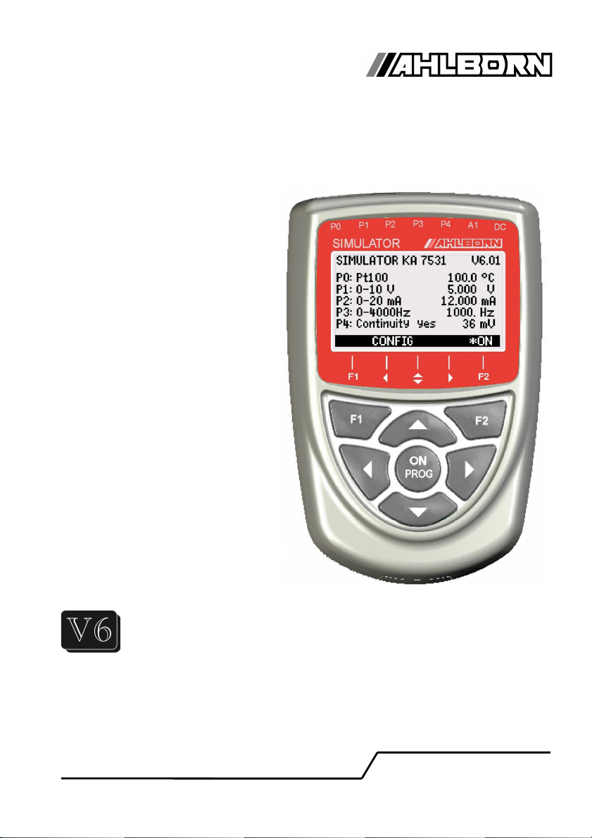
Simulator
ALMEMO® KA 7531
V1.4
03.12.2012
www.ahlborn.com

1. Operating Controls
1. OPERAT NG CONTROLS
(1) Signal sockets P0 to P4
for AL E O® clamp connectors
P0 Pt100
P1 10V, 60mV, thermocouples
P2 20mA
P3 Digital signals
P4 Continuity check
(2) Output socket A1
A1 V24 Interface (ZA 1909-DK5)
USB (ZA 1919-DKU)
LWL (ZA 1909-DKL)
Ethernet (ZA 1945-DK)
(3) DC socket
DC ains adapter (ZA 1312NA1, 12V)
12V and RS422 (ZA 5099-FSV)
9V and USB (ZA 1919-DKUV)
(4) LCD, graphics display
7 rows for functions
1 row for softkeys F1,◄,▲,►, F2
Shown in brackets: <SET>
(5) Operating keys
<CONFIG> Device configuration
< ENU> ain menu, simulator
<☼ON> Display illumination ON
PROG Programming
▲, ▼, ►F: Function selection
<SET> To change the function
▲, ▼S: To set the steps
PROG Programming
▲, ▼, ►P: Data entry
<ESC> To cancel the function
Accessories
(7) Pt100 test connector
(8) ALMEMO® test cable
2 AL E O® KA7531
Rear of device:
(6) Battery compartment
3 AA alkaline-manganese batteries
7
8

Table of Contents
2. TABLE OF CONTENTS
1. OPERAT NG CONTROLS............................................................................2
3. GENERAL..................................................................................................... 4
3.1 Warranty...............................................................................................4
3.2 Standard delivery................................................................................4
3.3 Waste disposal....................................................................................5
4. SAFETY NSTRUCT ONS............................................................................5
4.1 Special notes on use...........................................................................5
4.2 Handling batteries / rechargeable batteries correctly......................5
5. THE S MULATOR FUNCT ONS...................................................................6
6. CONNECT NG THE S MULATOR................................................................6
7. POWER SUPPLY.........................................................................................7
7.1 Battery operation and supply voltage monitoring............................7
7.2 External power supply........................................................................7
7.3 Switching ON / OFF, reinitialization...................................................7
8. D SPLAY AND OPERAT NG CONTROLS...................................................8
8.1 Function keys......................................................................................8
8.2 Data entry.............................................................................................8
9. MENUS......................................................................................................... 9
9.1 Main menu...........................................................................................9
9.2 Submenus............................................................................................9
9.2.1 Pt100 output.................................................................................9
9.2.2 Voltage output, thermocouples...................................................10
9.2.3 Current output............................................................................10
9.2.4 Digital signal output....................................................................11
9.2.5 Continuity check.........................................................................11
9.3 Simulator functions...........................................................................12
9.3.1 Steps, manual............................................................................12
9.3.2 Steps, automatic.........................................................................12
9.3.3 Ramp, automatic........................................................................12
9.4 Device configuration.........................................................................13
9.4.1 Language...................................................................................13
9.4.2 Illumination and contrast.............................................................13
9.4.3 Battery voltage............................................................................13
9.4.4 Baud rate, data format................................................................13
10. SER AL NTERFACE................................................................................14
10.1 Programming via the interface.......................................................15
11. ELECTROMAGNET C COMPAT B L TY.................................................16
12. APPEND X................................................................................................17
12.1 Technical data.................................................................................17
12.2 Product overview............................................................................17
12.3 ndex................................................................................................. 18
13. YOUR CONTACT PARTNER...................................................................20
AL E O® KA7531 3

3. general
3. GENERAL
Congratulations on your purchase of this new and innovative AL E O® simu-
lator. It will allow you to perform a wide range of simulation runs on sensors
and transmitters and put data acquisition and automation systems into service
quickly and easily. It also accepts signals from Pt100 and thermocouple sen-
sors, e.g. 0-10 V, 0-20 mA, and pulses and frequencies, 0-100 kHz. With its
range of softkeys and its clear and readily understandable graphics display the
device is easy and convenient to operate. You are nonetheless advised to
properly familiarize yourself with the way the device functions and with its nu-
merous possibilities and to carefully read these operating instructions and the
basic information on sensors in the AL E O® anual. This is the best way to
avoid operating errors and prevent damage to the device. To help you find an-
swers to your questions as quickly and easily as possible an index is provided
at the end of these instructions and at the end of the anual.
3.1 Warranty
Each and every device, before leaving our factory, undergoes numerous qual-
ity tests. We provide a guarantee, lasting two years from delivery date, that
your device will function trouble-free. In the unlikely event that the device
proves defective and you need to return it please wherever possible use the
original packaging material for dispatch and enclose a clear and informative
description of the fault and of the conditions in which it occurs.
This guarantee will not apply in the following circumstances :
- The user attempts any form of unauthorized tampering and alteration inside the device.
- The device is used in environments or conditions for which it is not suited.
- The device is used with an unsuitable power supply and / or in conjunction
with unsuitable peripheral equipment.
- The device is used for any purpose other than that for which it is intended.
- The device is damaged by electrostatic discharge or lightning.
- The user fails to observe these operating instructions
The manufacturer reserves the right to change the product's characteristics in
the light of technical progress or to benefit from the introduction of new compo-
nents.
3.2 Standard delivery
When you unpack the device check carefully for any signs of transport damage
and ensure that delivery is complete:
Simulator AL E O® KA 7531, AL E O® clamp connector, test cable with
test probes, These operating instructions, AL E O® anual,
CD with A R-Control software and various useful accessories
In the event of transport damage please retain the packaging material and in-
form your supplier immediately.
4 AL E O® KA7531
Waste disposal
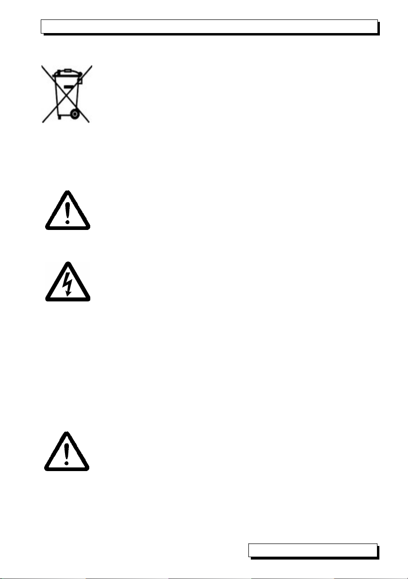
3.3 Waste disposal
This symbol means that the product is subject to European
Union regulations on segregated waste disposal. This applies
both to the product itself and to any accessories marked with
the same symbol. Disposal of any such item as unsorted do-
mestic waste is strictly forbidden. Batteries and rechargeable
battery packs are special waste and must not be discarded as
normal domestic waste. Please dispose of packaging materials,
plastics, and electronic components separately and in the
proper manner.
4. SAFETY NSTRUCT ONS
CAUT ON! This sign is intended to warn the user of a situation
that risks damaging the device. The user should carefully read
the operating instructions in order to avoid possible errors, dam-
age to equipment, and even the risk of personal injury. The de-
vice may only be opened by duly authorized and qualified service
technicians.
WARN NG! This sign is intended to warn the user of a possibly
life-threatening situation with risk of fatal injury through high volt-
age. Before connecting any equipment to the power supply al-
ways ensure that the operating voltage is correct. Please note
that the device may be susceptible to damage by electrostatic
discharge or lightning. Do not run wires in the vicinity of high-volt-
age power cables!
4.1 Special notes on use
If the device is brought into the work-room from a cold environ-
ment there is a risk that condensation might form on the electron-
ics. You are advised therefore to wait until the device has ad-
justed to the ambient temperature before starting to use it.
4.2 Handling batteries / rechargeable batteries correctly
When inserting batteries / rechargeable batteries ensure that
these are correctly polarized. If the device will probably not be
needed for a relatively long period of time or if the batteries are
empty remove the batteries; this will prevent battery acid leaking
onto the device and damaging it. Rechargeable batteries should
be recharged as and when necessary. You should never attempt
to recharge an ordinary (non-rechargeable) battery; it may ex-
plode ! Batteries / rechargeable batteries must never be short-cir-
cuited or thrown on the fire.
AL E O® KA7531 5

5. The simulator functions
5. THE S MULATOR FUNCT ONS
Simulator AL E O® KA7531 is a universal generator of sensor and transmit-
ter variables. For Pt100 sensors it incorporates 5 precision resistors in 4-con-
ductor circuitry. Voltage signals from 7 different thermocouple types with set-
table cold junction temperature are calculated and output via a 16-bit D/A con-
verter. Transmitter signals 0-10 V and 0-20 mA are generated in exactly the
same way. Pt100, voltage, and current signals are electrically isolated from
one another. The output values can be specified digit-by-digit or set manually
in selectable steps or automatically. It even provides continuous ramp genera-
tion with settable limit values. Digital signals of 0.01 Hz to 500 kHz can be
used as frequency with selectable pulse width or pulse / pause duration. A
continuity check is also provided; this measures the voltage drop and, in the
event of the result exceeding a settable threshold, issues an acoustic signal.
The simulator can also, via the interface, be controlled from a PC or operated
in an AL E O® network.
6. CONNECT NG THE S MULATOR
To supply simulator variables to the appropriate devices the simulator incor-
porates 5 AL E O® sockets P0 to P4 (1). The accessories include one
AL E O® test connector (7) with 6 terminals for connecting the Pt100 resis-
tors in 4-conductor circuitry. For all other signals there is the connector with
two-pole cable and banana plugs. For the continuity check test probes are
also provided.
Connection of Pt100 simulator with AL E O® test connector ZA 100-TS in 4-
conductor circuitry (terminals A, B, C, D):
Connection of voltage signals, current signals, digital signals, and continuity
check via 2-contact AL E O® test cable ZA 1000-TK fitted with banana plugs,
(terminals A = +, B = -):
6 AL E O® KA7531

Power supply
7. POWER SUPPLY
Power can be supplied to the simulator in any of the following ways :
3 AA alkaline batteries, in the device
ains adapter 12 V, 0.2 A, with AL E O® connector ZA1312NA1
External DC voltage, 10 to 30 V via AL E O® connector ZA1000FSV
Supply and RS422 network connection via AL E O® connector ZA5099FSV
Supply and USB connection via AL E O® data cable ZA1919DKUV
7.1 Battery operation and supply voltage monitoring
The measuring instrument is powered by 3 AA alkaline batteries. Basic current
consumption is approx. 30 mA; this will give an operating time of approx. 70
hours. If the display illumination is left switched on, this operating time will be
reduced to approx. 30 hours. If the current output is often used the batteries
may last as little as 15 hours. The available operating voltage is displayed in
the device configuration (see 9.4), thus allowing you to assess the remaining
operating time. As soon as the remaining battery capacity drops to approx.
10%, the battery symbol ´´µµµµµµµµµ¶ in the softkey bar of the displays will start to
flash and display illumination is switched off. If the batteries are completely dis-
charged the device itself will switch off. To replace old batteries unscrew the
battery compartment cover (6) on the rear of the device.
To save on battery use when in battery mode the electrically isolated
current / voltage signals P1 and P2, so long as they are not selected,
are switched off.
7.2 External power supply
Via the simulator it is also possible to draw power from an external source -
preferably using mains adapter ZA1312NA1 (12 V / 0.2 A) connected via the DC
socket (3). Please ensure that the mains voltage is correct. At this socket it is
also possible, via an AL E O® connector (ZA1000FSV) to connect a DC volt-
age from 9 to 12 V (minimum 0.2 A). Another interesting possibility is the com-
bined connection of power supply and interface to the AL E O® network via
AL E O® connector ZA5099FSV or to a USB interface via AL E O® cable ZA
1919-DKUV.
With an external supply all outputs can be used simultaneously.
7.3 Switching ON / OFF, reinitialization
To switch the device ON briefly press and release the key ON (5) in the middle
of the keypad; to switch the device OFF press the key ON and hold down. If
interference (e.g. electrostatic) or a malfunction (e.g. battery failure) causes the
device to behave abnormally, it can be reinitialized; to do so press key F2 .
when switching on. This will restore all settings to the factory default status.
AL E O® KA7531 7

8. Display and operating controls
8. D SPLAY AND OPERAT NG CONTROLS
The simulator incorporates a keypad (4) and a
graphic display (5) for the purposes of configur-
ing the device and operating all signals. The
main menu shows the associated ports P0 to P4
and the variables set.
8.1 Function keys
The way in which the function keys F1 , F2 (5)
and the cursor keys ◄ , ► , ▲ , ▼ operate
may vary from menu to menu. The function is in-
dicated as an abbreviation in the bottom line of
the display (softkeys).
In the instructions and documentation these soft-
key abbreviations are shown in angle brackets.
e.g.
To select device configuration <CONFIG>
To return to main menu < ENU>
To switch display illumination ON / OFF <*
ON> , <*
OFF>
To switch device OFF press and hold down ON
To select a function press any of keys PROG , ▲ oder ▼ ...
Symbol lights up in the middle indicating function
selection.
<F> für Funktionswahl
The function is highlighted in inverse font. 100.0 °C
To access the next submenu press ►F
Depending on the function the keys are assigned
an abbreviation.
To set a parameter directly <SET>
To cancel the function <ESC>
8.2 Data entry
If a programmable function is selected you can clear or reprogram the current
value directly.
To program press PROG
Symbol lights up in the middle indicating pro-
gramming mode.
<P>
The cursor blinks below the first input position. P1: 0-10V:
00.000
V
To clear the programmed values < CLR >
To increment the selected digit ▲ ...
To decrement the selected digit ▼ ...
8 AL E O® KA7531
SIMULATOR KA 7531 V6.01
P0: Pt100 100.0 °C
P1: 0-10 V 5.000 V
P2: 0-20 mA 12.000 mA
P3: 0- 000Hz 1000. Hz
P : Continuity yes 36 mV
CONFIG *ON
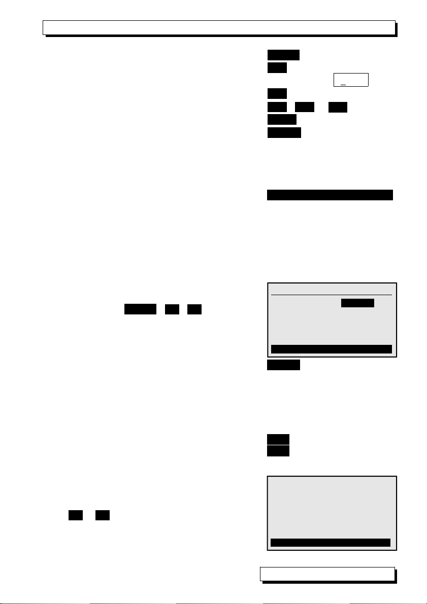
Data entry
To change the arithmetic sign < +/- >
To select the next position ►
The cursor blinks below the second digit. P1: 0-10V:
10.000
V
To move back to the previous digit ◄
Each position is programmed like the first.
▲ / ▼ ..., ► ...
To complete data input PROG
To cancel programming <ESC>
If a data cable or interface connector is plugged in at socket A1 or
DC, key operation on the simulator is - for safety reasons - automati-
cally blocked.
The following should appear in the softkey bar:
Remote Control ! *ON
9. MENUS
The simulator is operated via the main menu and a series of associated sub-
menus in which its operating parameters can be individually set.
9.1 Main menu
In the main menu all parameters for output
ports P0 to P3 can be selected and set directly
by means of keys PROG , ▲ / ▼ . see 8.2.
The threshold for the continuity check can be
programmed via port P4. The ports can be
configured in detail via the appropriate sub-
menus.
The 5 Pt100 values can also be selected by
means of.
<SET>
9.2 Submenus
Passing via the main menu to the submenus all ports P0 to P4 can be config-
ured in detail and simulation functions can be activated.
To call up these submenus press F►
To return to the main menu press F◄
9.2.1 Pt100 output
At socket P0 there are 5 resistors in 4-conduc-
tor circuitry for simulating Pt100 sensors. (see 6.)
In submenu P0 Pt100 you can by means of
keys ▲ / ▼ (abbreviation S for steps) scroll up
and down between the 5 temperature values 0,
50, 100, 200, and 300 °C.
AL E O® KA7531 9
P0: Output Pt100
Function: steps individually
100.0 °C
Fª S *ON
SIMULATOR KA 7531 V6.01
P0: Pt100 100.0 °C
P1: 0-10 V 5.000 V
P2: 0-20 mA 12.000 mA
P3: 0- 000Hz 1000. Hz
P : Continuity yes 36 mV
ESC F ©F SET

9. enus
9.2.2 Voltage output, thermocouples
The voltage output is present at socket P1. see6.
In associated submenu P1 the following voltage
ranges can be selected:
-3 to 10V,
-10 to 60mV
plus 7 thermocouple ranges:
TC NiCr type K 0.1°C
TC Nisil type N 0.1°C
TC FeCo type J 0.1°C
TC CoCo type T 0.1°C
TC Pt10 type S 1 °C
TC Pt13 type R 1 °C
TC El18 type B 1 °C
To select function ´
P1: Output
´ press (see 9.3)
:
PROG , ▲ / ▼ see
To choose the output range P1: Output -10...60mV
press: <SET> or see
To choose simulator functions Function: Stes individually
press: <SET> oder see
Display of temperature value in mV U: 20.6 mV
To simulate real temperatures the cold junction
temperature (socket temperature of test item)
must either be disabled in the test item or im-
aged in the simulator.
To select the cold junction temperature press <VK>
Enter the cold junction temperature
in the function press VK: 20.6°C see
To enable / disable the cold junction temperature PROG , <OFF> / <ON>
Display of temperature value in mV <mV>
To return to simulator’s main menu F◄
9.2.3 Current output
The current output is present at socket P2. see6.
In submenu P2 the current range is fixed per-
manently at 0 to 20 mA.
To choose simulator functions (see 9.3) Funktion: Steps individually
To return to simulator’s main menu F◄
10 AL E O® KA7531
P1: Output 0 - 10V
Function steps automatically
5.000 V
Step: 01.000 V
Fª S *ON
P1: Output TC NiCr type K
Function: steps individually
500.0 °C
Step: 0100.0°C U: 20.6 mV
ESC F SET
P2: Output 0...20 mA
Function: steps individually
5.000 mA
Step: 01.000 mA
Fª S *ON

Submenus
9.2.4 Digital signal output
Frequencies
For frequencies and pulses socket P3 is pro-
vided. In submenu P3 the following can be se-
lected : 4 frequency ranges
1 to 4000 Hz,
1 to 10.00 kHz
1 to 40.0 kHz
1 to 100 kHz
Within these ranges the pulse width and the
pulse / pause ratio can be set in %.
pulse width: 50.0 %
Pulses
There are also two pulse ranges for which the
period duration is specified :
2 µs to 99.999 ms
2 ms to 99.999 s
The pulse duration can also be set here. Pulse duration: 01.000 ms
Pulse variables, an overview
For a clear and easy-to-understand overview of
these variables (frequency, pulse width, pulse
duration, pause duration) there is a further sub-
menu; this can be accessed by pressing the
►F key again.
To return to the 1st submenu press: F◄
9.2.5 Continuity check
The test cable connected at socket P4 provides
a continuity check. The threshold above which
continuity is reported (by visual and acoustic
signals) can be set between 1 and 1000 mV.
The displayed measured value indicates the
voltage drop, e.g. the voltage flowing through a
diode.
AL E O® KA7531 11
P3: Output Frequency 000Hz
Function: steps individually
1000 Hz
Pulse width: 50.0 %
Step: 00100 Hz
Fª S ©F *ON
P3:Outp. Period duration 99ms
Function: steps individually
10.000 ms
Pulse duration: 01.000 ms
Step: 02.000 ms
Fª S ©F *ON
P : Continuity jes
650 mV
Threshold: 1000 mV
Fª *ON
P3:Outp. Period duration 99ms
Frequency: 100 Hz
Period duration: 10.000 ms
pulse width: 10.0 %
Pulse duration: 01.000 ms
Step: 02.000 ms
Fª S *ON
9. enus
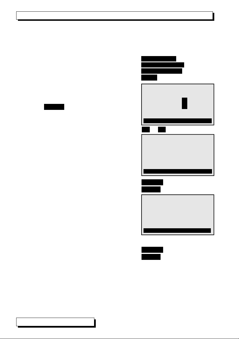
9.3 Simulator functions
To run a quick and easy check on a control process or a control element vari-
ous values can be systematically specified either in steps or automatically in
ramp form. To do this select the ´Function´ line (see 8.1).
Program one of the available functions Steps manual
Steps automatic
Ramp automatic
or by means of key (see 8.2) <SET>
9.3.1 Steps, manual
In this function the output value can be selected
and modified manually digit-by-digit; to termi-
nate press <PROG> . (see 8.2)
To specify a step percentage select the function
´Steps´ (see 8.1) and enter the desired value.
To change the control variable step-by-step press ▲ or ▼ (softkey abbreviation S)
9.3.2 Steps, automatic
In this function ´Steps automatically´modifica-
tion of the control variable can be automated.
In the function ´Time´ the waiting period per
step can be entered.
To start step-by-step output press: <START>
To stop step-by-step output press: <STOP>
9.3.3 Ramp, automatic
In this function the control variable is simulated
automatically and continuously from a start
value up to a stop value or for a certain period
of time. One can enter a start value; one can
also enter a stop value in the ´Stop´ function
and the period of time from start to stop in the
´Time´ function.
To start continuous output press: <START>
To start continuous output press: <STOP>
12 AL E O® KA7531
P3: Outp.Period duration 99ms
Function: Ramp automatically
Start: 10.000 ms
Pulse duration:: 99.999 ms
Stop: 50.000 ms Time: 999 s
START Fª S ©F *ON
P1: Output 0...10 V
Function: Steps manual
5.000 V
Step: 01.000 V
D
P1: Output 0...10 V
Function: Steps automatically
5.000 V
Step: 01.000 V Time: 10 s
START Fª S *ON

Device configuration
9.4 Device configuration
In the menu ´DEVICE CONFIGURATION´ certain
basic settings for the adapter can be made.
namely the operating parameters ´Device ad-
dress´ and ´Baud rate´ for the serial interface,
the menu language, and the display illumination
mode.
To select ´Device configuration´ in the main menu <CONFIG>
To return to the main menu: < ENU>
9.4.1 Language
As menu language the user can choose between ´Deutsch´ / ´English´ /
´Français´; (other languages are available on request).
The softkeys are international; these cannot be changed.
To select the ´Language´ function: Language: English
To change the language <SET>
9.4.2 llumination and contrast
The display can be illuminated but this consumes more power. In battery
mode therefore backlighting switches off automatically on expiry of a settable
period of time during which no key is touched.
To switch display illumination ON <* ON> Illumination:
To switch display illumination OFF <* OFF> Illumination: -
To enter a duration for display illumination ON Duration: 20 sec
To switch illumination ON permanently Duration: - -
To switch back ON again without this function ON or ◄
Set the contrast (5 to 100 %) in the function Contrast: 50%
9.4.3 Battery voltage
View current operating voltage UBat: .5 V
As soon as battery voltage drops below 3.5 V dis-
play illumination is switched OFF automatically.
Symbol ´´µµµµµµµµµ¶ in place of <* ON>
As soon as battery voltage drops below 3.0 V the
device itself is switched OFF automatically
9.4.4 Baud rate, data format
On leaving the factory the baud rate for all interface modules is programmed to
9600 baud. In order to avoid unnecessary problems when networking several
devices together the baud rate should not be altered; instead, the computer
should be set to match. If for some reason this proves impossible you can, in
the ´Baud rate´ function, choose a value from 1200 / 2400 / 4800 / 9600 baud
or 57.6 / 115.2 kilobaud. Set the baud rate in the function (s. 8.2):Baud rate: 9600 bd
Data format 8 data bits, 1 stop bit, no parity (cannot be changed)
AL E O® KA7531 13
* DEVICE CONFIGURATION *
Device address: 00
Baud rate: 9600 Bd
Language: English
Illumination: Øduration: 20sec
Contrast: 50 % UBat: .5 V
MENU *ON
9. enus
9.4.5 Device address
To communicate with networked devices it is absolutely essential that all the
devices concerned should have the same baud rate setting but that each
should have its own dedicated address; this is because only one device should
respond per command. Before starting network operation ensure therefore that
all the measuring instruments and modules involved are assigned different de-
vice addresses. On leaving the factory address 00 is normally set.
Set the device address in the function (see 8.2): Device address: 00
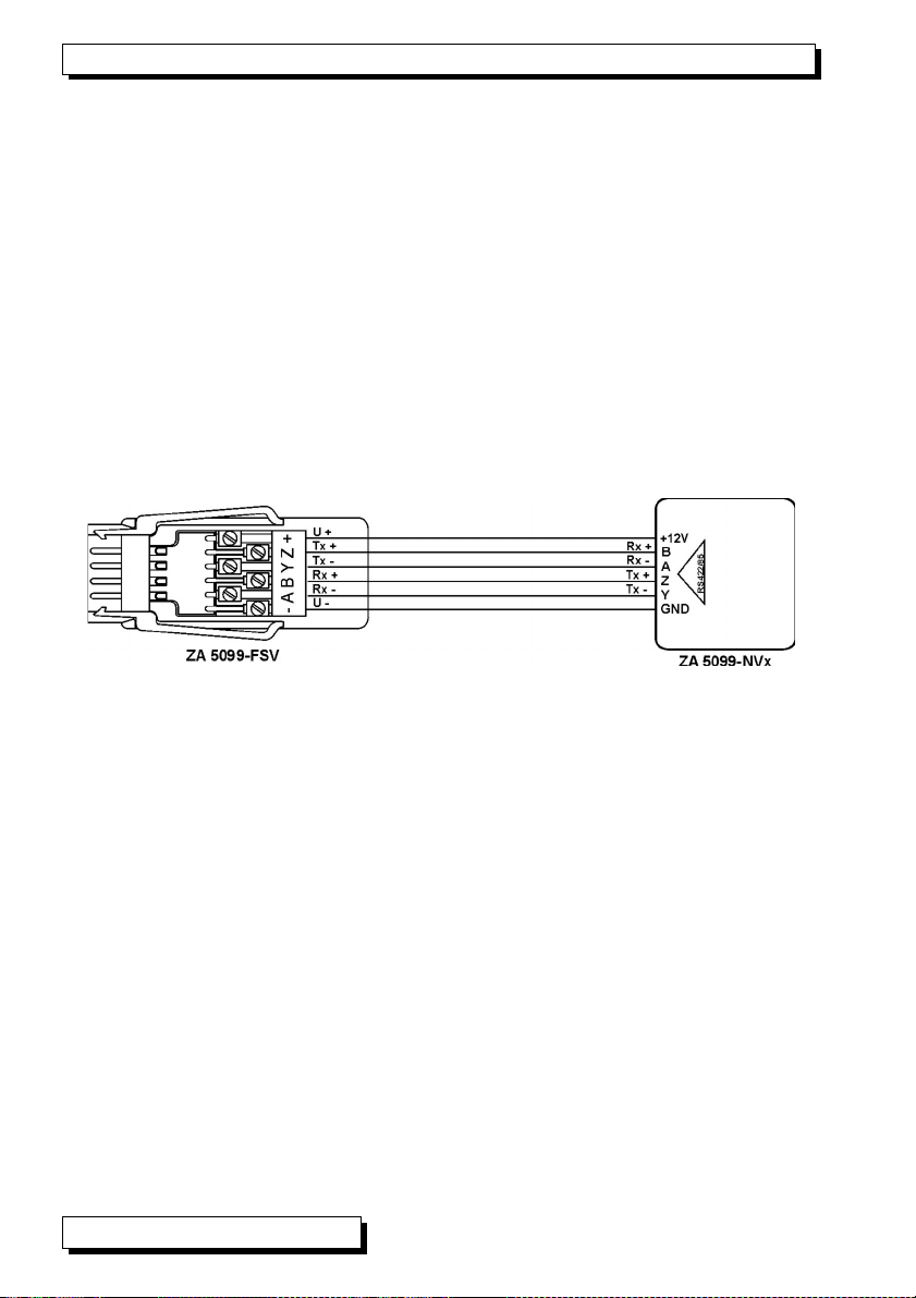
10. SER AL NTERFACE
All ports can be controlled not only by pressing the appropriate keys but also,
with option I, via the serial interface; (see anual, Chapter 6). For connecting
to socket A1 (2) various data cables are available; (see anual 5.2). The best
way of connecting to a network distributor is on a 6-wire basis via connector ZA
5099-FSV in the DC socket leading to a free RS422 output; (see anual 5.3).
This combines power supply and data transmission.
The same combined connection is also implemented with the new USB data
supply cable ZA 1919-DKUV.
If a data cable or interface connector is plugged in at socket A1 or
DC, key operation on the simulator is - for safety reasons - automati-
cally blocked.
The following should appear in the softkey bar:
Remote Control ! *ON
The ´Device address´ can be modified as and when necessary in the menu
´DEVICE Configuration´. (see 9.4.5)
14 AL E O® KA7531

Programming via the interface
10.1 Programming via the interface
To program a function Command
Port 01 range V i01 B11
Port 01 range mV i01 B10
Port 01 range TC type K i01 B04
Port 01 range TC type N i01 B34
Port 01 range TC type J i01 B35
Port 01 range TC type T i01 B36
Port 01 range TC type S i01 B07
Port 01 range TC type R i01 B37
Port 01 range TC type B i01 B08
Port 03 range 4000Hz i03 B29
Port 03 range 10kHz i03 f1 B29
Port 03 range 40kHz i03 f2 B29
Port 03 range 100kHz i03 f3 B29
Port 03 range 99ms i03 B54
Port 03 range 99s i03 f1 B54
Cold junction temperature in digits (e.g. 23.4°C) f1 g00234
Value of simulator port pp to 5 digits ipp f9 ayyyyy Aufl. s.u.
Output programming and status
f3 P19
Response Simulator
Px nterface element Variant P0.KA7531
00 Pt100 output Controlled 00:TO0 COM +0300.0°C
01 Analog output, 10 V Controlled 01:DA1 COM +10.000 V
01 Analog output, 60 mV Controlled 01:DA7 COM +60.000 V
01 Analog output, TC type K Controlled 01:TC0 COM +1370.0°C VK:+025.1°C
01 Analog output, TC type N Controlled 01:TC1 COM +1300.0°C VK: - - -°C
01 Analog output, TC type J Controlled 01:TC2 COM +1000.0°C VK: - - -°C
01 Analog output, TC type T Controlled 01:TC3 COM +0400.0°C VK: - - -°C
01 Analog output, TC type S Controlled 01:TC4 COM +01760.°C VK:+0025.°C
01 Analog output, TC type R Controlled 01:TC5 COM +01760.°C VK: - - -°C
01 Analog output, TC type B Controlled 01:TC6 COM +01800.°C VK: - - -°C
02 Analog output, 20 mA Controlled 02:DA2 COM +20.000 A
03 Frequency output, 0.4 kHz Controlled 03:FO0 COM +04000.Hz
03 Frequency output, 10 kHz Controlled 03:FO1 COM +010.00kH
03 Frequency output, 40 kHz Controlled 03:FO2 COM +0040.0kH
03 Frequency output, 100 kHz Controlled 03:FO2 COM +00100.kH
03 Pulse output, 99 ms Controlled 03:PO0 COM +99.999 s
03 Pulse output, 99 s Controlled 03:PO1 COM +99.999 s
04 Continuity voltage 04:IN0 +01000. V DS:+0500. V
AL E O® KA7531 15

11. Electromagnetic compatibility
11. ELECTROMAGNET C COMPAT B L TY
Ahlborn ess- und Regelungstechnik GmbH declares herewith that measuring
instrument AL E O® KA 7531 carries the CE label and complies in full with
the requirements of EU directives relating to low voltage and to electromag-
netic compatibility (E C) (89/336/EWG).
The following standards have been applied in evaluating the product.
Safety / security: EN 61010-1:2001
E C: EN 61326-1: 2013
If a product is modified in any manner not agreed with us
in advance, this declaration becomes void.
16 AL E O® KA7531

Appendix
12. APPEND X
12.1 Technical data
Pt100 5 resistors in 4-conductor circuitry, electr. isolated
Temperature values 0, 50, 100, 200, 300 °C
Accuracy ±0.1 °C Temperature drift 0.01 °C/K
Analog outputs Electr. isolated Resolution 15 bits
-4.0 to +10.000 V Load >100 kΩ
-10.0 to +60 000 mV Load >1 Ω
0.0 to +20 000 mA Load <500 Ω
Accuracy ±0.05% ±0.05% of final val. Temp. drift 20 ppm / K
Time constant 100 µs
Thermocouple ranges Types K, N, T, J (ITS90) Resolution 0.1 K
Types S, R, B (ITS90) Resolution 1 K
Accuracy ±0.05% ±0.05% of final value
Temp. range for cold junction compensation -30 to +100 °C
Frequency ranges 1 to 4000 Hz; 0.01 to 10.00 kHz; 0.1 to 40.0 kHz; 1 to 100 kHz
Accuracy as per resolution
Pulse ranges Period duration Pulse duration
2 µs to 99.999 ms 1 µs to 99.998 ms
2 ms to 99.999 s 1 ms to 99.998 s
Accuracy 0.01%
Continuity check Current appr. 1 mA Threshold 0 to 1000 mV
Power supply 10 to 12 VDC
Current consumption Standard approx. 30 mA
From battery 4.5 V With voltage / current output approx. 80mA + 4x IOUT
Illumination approx. 40 mA extra
Standard equipment Graphics display 126 x 64 (55x30 mm) 7 silicone keys
Housing (LxWxH) 127x83x42mm, ABS, Weight approx. 260g
Suitable conditions
Operating temperature -10 to +50 °C Storage temperature -20 to +60 °C
Ambient relative humidity 10 to 90 % RH (non-condensing)
12.2 Product overview
ALMEMO®-Simulator
Pt100, 7 thermocouples -10 to +60 mV, -3 to +10 V, 0 to 20 mA, 0 to 500 kHz
Continuity check, graphics display, keypad, AL E O® clamp connector,
AL E O® test cable, test probes KA 7531
Option I Interface for control via PC OA 7531-I
Accessories
AL E O® test cable with test probes ZA 1000-TK
ains adapter with AL E O® connector, 12 V, 0.2 A ZA 1312-NA1
AL E O® supply connector ZA 1000-FSV
AL E O® data cable, V24 interface, el. isol., max. 115.2 kilobaud ZA 1909-DK5
AL E O® data supply cable, USB interface, 9 V, 200 mA ZA 1919-DKU
AL E O® data supply connector with RS422 interface ZA 5099-FSV
AL E O® KA7531 17
Order No.

12. Appendix
12.3 ndex
4-conductor circuitry 6 6
Accessories 12.2 17
Accuracy 12.1 17
Analog outputs 12.1 17
available operating voltage 7.1 7
Battery operation 7.1 7
Battery voltage 9.4.3 13
Baud rate 9.4.4 13
cold junction temperature 9.2.2 10
Connecting the simulator 6 6
Continuity check 12.1 11, 17
contrast 9.4.2 13
current consumption 7.1 7
Current consumption 12.1 17
Current output 9.2.3 10
Data entry 8.2 8
data format 9.4.4 13
data supply cable 12.2 14, 17
Device address 9.4.5 14
Device configuration 9.4 13
Digital signal output 9.2.4 11
Display and operating controls 8 8
duration for display illumination 9.4.2 13
Electromagnetic compatibility 11 16
External power supply 7.2 7
factory default status 7.3 7
frequency ranges 9.2.4 11
Frequency ranges 12.1 17
Function keys 8.1 8
Handling batteries 4.2 5
illumination 8.1 8
Illumination 9.4.2 13
Language 9.4.1 13
ain menu 9.1 9
ains adapter 7 7
menu language 9.4 13
enus 9 9
network distributor 10 14
network operation 9.4.5 14
Operating Controls 1 2
operating time 7.1 7
Order No. 12.2 17
period duration 9.2.4 11
18 AL E O® KA7531

Index
Power supply 12.1 7, 17
Programming via the interface 10.1 15
Pt100 12.1 17
Pt100 output 9.2.1 9
pulse / pause ratio 9.2.4 11
pulse duration 9.2.4 11
pulse range 9.2.4 11
Pulse ranges 12.1 17
pulse width 9.2.4 11
Ramp 9.3.3 12
reinitialization 7.3 7
Remote Control 10 14
replace old batteries 7.1 7
Safety instructions 4 5
select a function 8.1 8
Serial interface 10 14
Signal sockets 1 2
simulator functions 5 6
Simulator functions 9.3 12
softkey 8.1 8
Special notes on use 4.1 5
Standard delivery 3.2 4
Standard equipment 12.1 17
start 9.3.2 12
start value 9.3.3 12
step percentage 9.3.1 12
Steps 9.3.1 12
stop 9.3.2 12
stop value 9.3.3 12
Submenus 9.2 9
Suitable conditions 12.1 17
supply voltage monitoring 7.1 7
Switching ON / OFF 7.3 7
Temp. range for cold junction compensation 12.1 17
test cable 6 6
test connector 6 6
thermocouple ranges 9.2.2 10
Thermocouple ranges 12.1 17
threshold 9.2.5 11
Time constant 12.1 17
voltage flowing 9.2.5 11
Voltage output, thermocouples 9.2.2 10
waiting period 9.3.2 12
Warranty 3.1 4
Waste disposal 3.3 5
AL E O® KA7531 19

13. Your contact partner
13. YOUR CONTACT PARTNER
AHLBORN ess- und Regelungstechnik GmbH
Eichenfeldstraße 1
83607 Holzkirchen
Germany
internet : http://www.ahlborn.com
e-mail : [email protected]
Even the greatest possible care cannot exclude the possibility of inaccuracies.
We reserve the right to make technical changes without advance notice.
20 AL E O® KA7531
Table of contents
Popular Test Equipment manuals by other brands


Redtech
Redtech TRAILERteck T05 user manual

Venmar
Venmar AVS Constructo 1.0 HRV user guide

Test Instrument Solutions
Test Instrument Solutions SafetyPAT operating manual

Hanna Instruments
Hanna Instruments HI 38078 instruction manual

Kistler
Kistler 5495C Series instruction manual

Waygate Technologies
Waygate Technologies DM5E Basic quick start guide

StoneL
StoneL DeviceNet CK464002A manual

Seica
Seica RAPID 220 Site preparation guide

Kingfisher
Kingfisher KI7400 Series Training manual

Kurth Electronic
Kurth Electronic CCTS-03 operating manual

SMART
SMART KANAAD SBT XTREME 3G Series user manual

Agilent Technologies
Agilent Technologies BERT Serial Getting started