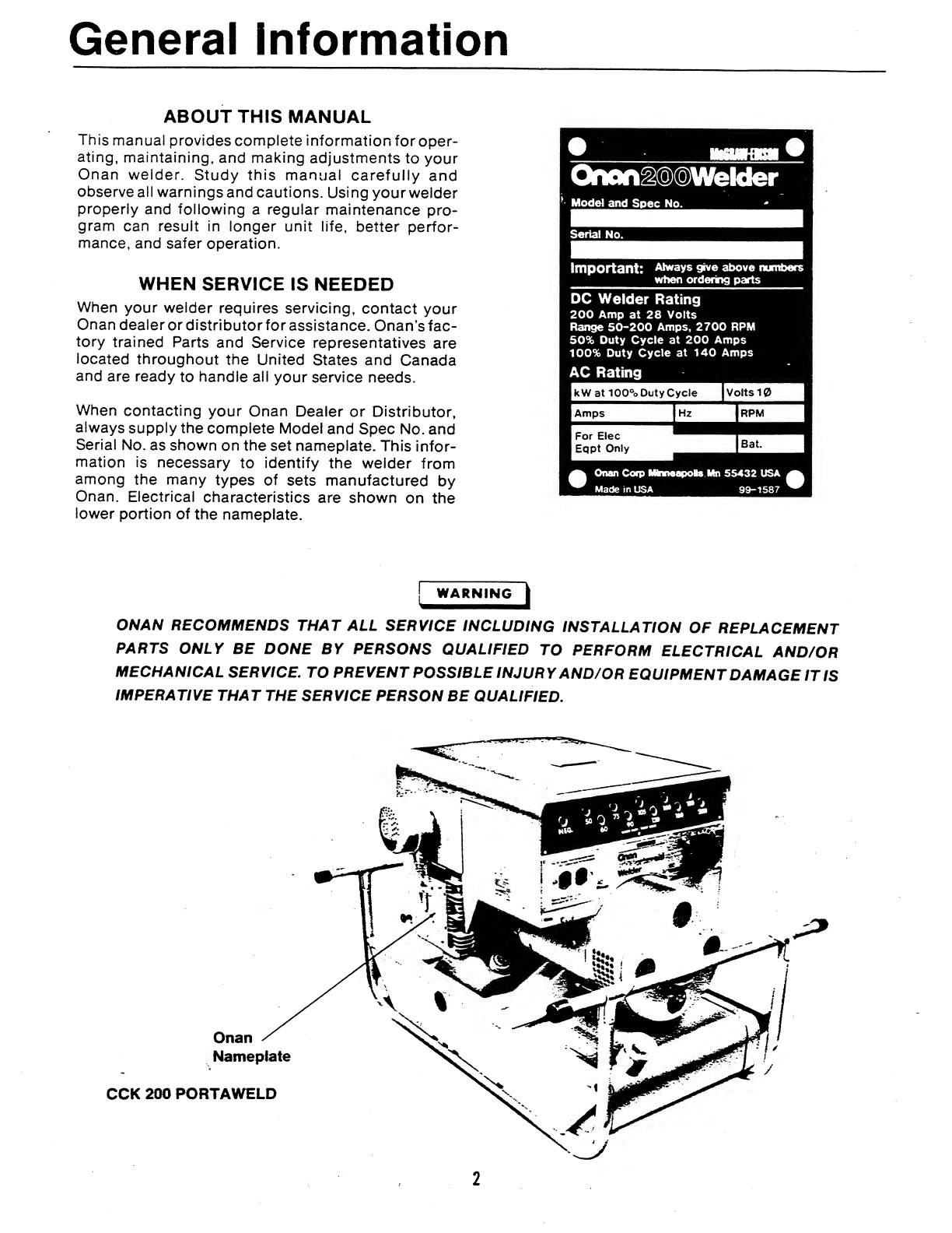
Onan 200 Portaweld CCK User manual

MC6RAUHDIS0IU
Operators
Manual
200
Portaweld®
Welder
•
Gasoline
Driven
Welder
•
Two
Cylinder
Air
Cooled
927-0155
SPEC
T
1-82

Important
Safety
Precautions
Read
and
observe
these
safety
precautions
when
using
or
working
on
electric
generators,
engines
and
related
equipment.
Also
read
and
follow
the
literature
provided
with
the
equipment.
Proper
operation
and
maintenance
are
critical
to
perfor¬
mance
and
safety.
Electricity,
fuel,
exhaust,
moving
parts
and
batteries
present
hazards
that
can
cause
severe
personal
injury
or
death.
FUEL,
ENGINE
OIL,
AND
FUMES
ARE
FLAMMABLE
AND
TOXIC
Fire,
explosion,
and
personal
injury
can
result
from
im¬
proper
practices.
•
Used
engine
oil,
and
benzene
and
lead,
found
in
some
gasoline,
have
been
identified
by
government
agencies
as
causing
cancer
or
reproductive
toxicity.
When
checking,
draining
or
adding
fuel
or
oil,
do
not
ingest,
breathe
the
fumes,
or
contact
gasoline
or
used
oil.
•
Do
not
fill
tanks
with
engine
running.
Do
not
smoke
around
the
area.
Wipe
up
oil
or
fuel
spills.
Do
not
leave
rags
in
engine
compartment
or
on
equipment.
Keep
this
and
surrounding
area
clean.
•
Inspect
fuel
system
before
each
operation
and
peri¬
odically
while
running.
•
Equip
fuel
supply
with
a
positive
fuel
shutoff.
•
Do
not
store
or
transport
equipment
with
fuel
in
tank.
•
Keep
an
ABC-rated
fire
extinguisher
available
near
equipment
and
adjacent
areas
for
use
on
all
types
of
fires
except
alcohol.
•
Unless
provided
with
equipment
or
noted
otherwise
in
installation
manual,
fuel
lines
must
be
copper
or
steel,
secured,
free
of
leaks
and
separated
or
shielded
from
electrical
wiring.
•
Use
approved,
non-conductive
flexible
fuel
hose
for
fuel
connections.
Do
not
use
copper
tubing
as
a
flex¬
ible
connection.
It
will
work-harden
and
break.
EXHAUST
GAS
IS
DEADLY
•
Engine
exhaust
contains
carbon
monoxide
(CO),
an
odorless,
invisible,
poisonous
gas.
Learn
the
symptoms
of
CO
poisoning.
•
Never
sleep
in
a
vessel,
vehicle,
or
room
with
a
gen-
set
or
engine
running
unless
the
area
is
equipped
with
an
operating
CO
detector
with
an
audible
alarm.
•
Each
time
the
engine
or
genset
is
started,
or
at
least
every
day,
thoroughly
inspect
the
exhaust
system.
Shut
down
the
unit
and
repair
leaks
immediately;
•
Warning:
Engine
exhaust
is
known
to
the
State
of
California
to
cause
cancer,
birth
defects
and
other
reproductive
harm.
Make
sure
exhaust
is
properly
ventilated.
•
Vessel
bilge
must
have
an
operating
power
exhaust.
•
Vehicle
exhaust
system
must
extend
beyond
ve¬
hicle
perimeter
and
not
near
windows,
doors
or
vents.
•
Do
not
use
engine
or
genset
cooling
air
to
heat
an
area.
•
Do
not
operate
engine/genset
in
enclosed
area
without
ample
fresh
air
ventilation.
•
Expel
exhaust
away
from
enclosed,
sheltered,
or
occupied
areas.
•
Make
sure
exhaust
system
components
are
se¬
curely
fastened
and
not
warped.
MOVING
PARTS
CAN
CAUSE
SEVERE
PERSONAL
INJURY
OR
DEATH
•
Do
not
remove
any
guards
or
covers
with
the
equip¬
ment
running.
•
Keep
hands,
clothing,
hair,
and
jewelry
away
from
moving
parts.
•
Before
performing
any
maintenance,
disconnect
battery
(negative
[-]
cable
first)
to
prevent
acciden¬
tal
starting.
•
Make
sure
fasteners
and
joints
are
secure.
Tighten
supports
and
clamps,
keep
guards
in
position
over
fans,
drive
belts,
etc.
•
If
adjustments
must
be
made
while
equipment
is
running,
use
extreme
caution
around
hot
manifolds
and
moving
parts,
etc.
Wear
safety
glasses
and
pro¬
tective
clothing.
BATTERY
GAS
IS
EXPLOSIVE
•
Wear
safety
glasses
and
do
not
smoke
while
servic¬
ing
batteries.
•
Always
disconnect
battery
negative
(-)
lead
first
and
reconnect
it
last.
Make
sure
you
connect
battery
correctly.
A
direct
short
across
battery
terminals
can
cause
an
explosion.
Do
not
smoke
while
servicing
batteries.
Hydrogen
gas
given
off
during
charging
is
explosive.
•
Do
not
disconnect
or
connect
battery
cables
if
fuel
vapors
are
present.
Ventilate
the
area
thoroughly.
GSP-i
1
of
2

DO
NOT
OPERATE
IN
FLAMMABLE
AND
EXPLOSIVE
ENVIRONMENTS
Flammable
vapor
can
be
ignited
by
equipment
operation
or
cause
a
diesel
engine
to
overspeed
and
become
diffi¬
cult
to
stop,
resulting
in
possible
fire,
explosion,
severe
personal
injury
and
death.
Do
not
operate
diesel
equip¬
ment
where
a
flammable
vapor
environment
can
be
created
by
fuel
spill,
leak,
etc.,
unless
equipped
with
an
automatic
safety
device
to
block
the
air
intake
and
stop
the
engine.
HOT
COOLANT
CAN
CAUSE
SEVERE
PERSONAL
INJURY
•
Hot
coolant
is
under
pressure.
Do
not
loosen
the
coolant
pressure
cap
while
the
engine
is
hot.
Let
the
engine
cool
before
opening
the
pressure
cap.
ELECTRICAL
SHOCK
CAN
CAUSE
SEVERE
PERSONAL
INJURY
OR
DEATH
•
Do
not
service
control
panel
or
engine
with
unit
run¬
ning.
High
voltages
are
present.
Work
that
must
be
done
while
unit
is
running
should
be
done
only
by
qualified
service
personnel.
•
Do
not
connect
the
generator
set
to
the
public
utility
or
to
any
other
electrical
power
system.
Electrocu¬
tion
can
occur
at
a
remote
site
where
line
or
equip¬
ment
repairs
are
being
made.
An
approved
transfer
switch
must
be
used
if
more
than
one
power
source
is
connected.
•
Disconnect
starting
battery
(negative
[-]
cable
first)
before
removing
protective
shields
or
touching
elec¬
trical
equipment.
Use
insulative
mats
placed
on
dry
wood
platforms.
Do
not
wear
jewelry,
damp
clothing
or
allow
skin
surface
to
be
damp
when
handling
electrical
equipment.
•
Use
insulated
tools.
Do
not
tamper
with
interlocks.
•
Follow
all
applicable
state
and
local
electrical
codes.
Have
all
electrical
installations
performed
by
a
qualified
licensed
electrician.
Tag
open
switches
to
avoid
accidental
closure.
•
With
transfer
switches,
keep
cabinet
closed
and
locked.
Only
authorized
personnel
should
have
cabinet
or
operational
keys.
Due
to
serious
shock
hazard
from
high
voltages
within
cabinet,
all
service
and
adjustments
must
be
performed
by
an
electri¬
cian
or
authorized
service
representative.
If
the
cabinet
must
be
opened
for
any
reason:
1.
Move
genset
operation
switch
or
Stop/Auto/
Handcrank
switch
(whichever
applies)
to
Stop.
2.
Disconnect
genset
batteries
(negative
[-]
lead
first).
3.
Remove
AC
power
to
automatic
transfer
switch.
If
instructions
require
otherwise,
use
extreme
caution
due
to
shock
hazard.
MEDIUM
VOLTAGE
GENERATOR
SETS
(601V
TO
15kV)
•
Medium
voltage
acts
differently
than
low
voltage.
Special
equipment
and
training
are
required
to
work
on
or
around
medium
voltage
equipment.
Operation
and
maintenance
must
be
done
only
by
persons
trained
and
qualified
to
work
on
such
devices.
Im¬
proper
use
or
procedures
will
result
in
severe
per¬
sonal
injury
or
death.
•
Do
not
work
on
energized
equipment.
Unauthorized
personnel
must
not
be
permitted
near
energized
equipment.
Induced
voltage
remains
even
after
equipment
is
disconnected
from
the
power
source.
Plan
maintenance
with
authorized
personnel
so
equipment
can
be
de-energized
and
safely
grounded.
GENERAL
SAFETY
PRECAUTIONS
•
Do
not
work
on
equipment
when
mentally
or
physi¬
cally
fatigued
or
after
consuming
alcohol
or
drugs.
•
Carefully
follow
all
applicable
local,
state
and
feder¬
al
codes.
•
Never
step
on
equipment
(as
when
entering
or
leav¬
ing
the
engine
compartment).
It
can
stress
and
break
unit
components,
possibly
resulting
in
dan¬
gerous
operating
conditions
from
leaking
fuel,
leak¬
ing
exhaust
fumes,
etc.
•
Keep
equipment
and
area
clean.
Oil,
grease,
dirt,
or
stowed
gear
can
cause
fire
or
damage
equipment
by
restricting
airflow.
•
Equipment
owners
and
operators
are
solely
re¬
sponsible
for
operating
equipment
safely.
Contact
your
authorized
Onan/Cummins
dealer
or
distribu¬
tor
for
more
information.
KEEP
THIS
DOCUMENT
NEAR
EQUIPMENT
FOR
EASY
REFERENCE.
GSP-1
2
of
2

Safety
Precautions
ALWAYS
USE
PRECAUTIONARY
MEASURES
DUR¬
ING
ARC
WELDING
OPERATIONS
TO
ENSURE
MAXIMUM
PERSONAL
SAFETY
AND
THE
SAFETY
OF
NEARBY
PERSONNEL.
[
WARNING
|
This
symbol
is
used
through¬
out
this
manual
to
warn
of
possible
serious
personal
injury.
This
symbol
refers
to
possible
l—
e
quipment
damage.
•
Operate
and
Maintain
The
Machine
And
Its
Equipment
Properly.
Do
not
overload
the
cables.
Do
not
use
worn
or
poorly
connecting
cables.
Do
not
allow
the
welding
cables
to
contact
hot
metal,
water,
oil
or
grease.
Prevent
cables
from
becoming
a
stum¬
bling
hazard
by
keeping
them
in
order
and
out
of
the
way.
Use
electrode
holders
that
are
completely
in¬
sulated.
Do
not
use
holders
with
defective
jaws.
Do
not
use
the
welder
without
grounding
the
frame
or
the
case.
Do
not
ground
to
pipelines
carrying
gases
of
flammable
liquids.
Be
sure
the
conductors
can
safely
carry
the
grounding
current.
Keep
all
connections
clean
and
tight.
Do
not
use
an
electric
welder
on
an
engine
unless
both
the
engine’s
battery
cables
and
alternator
wires
are
disconnected.
•
Take
Precautions
Against
Electric
Shock.
NEVER
work
in
a
damp
area
without
suitable
insulation
against
shock.
NEVER
stand
in
water
or
on
a
wet
floor
or
use
wet
„
gloves
when
welding.
ALWAYS
dry
out
the
work
pieces
or
bench
if
there
is
any
evidence
of
moisture.
OPEN
power
circuits
before
inspecting
machines.
ALWAYS
turn
off
the
machine
when
leaving
the
work.
•
Do
Not
Weld
Near
Flammable
Materials.
NEVER
weld
in
or
near
EXPLOSIVE
AT¬
MOSPHERES.
Clean
any
container
that
has
heid
combustible
or
flammable
materials
by
approved
or
prescribed
methods.
A
very
small
amount
of
residual
gas
cr
liquid
can
cause
a
serious
explosion.
When
the
contacts
of
the
container
is
unknown,
use
an
explosimeter.
Use
carbon
dioxide
or
nitrogen
to
ventilate
a
container.
NEVER
USE
OXYGEN.
When
the
container
has
held
a
gas
or
liquid
that
readily
dissolves
in
water,
perform
the
following:
1.
Flush
the
container
several
times
with
water
and
a
wetting
agent
(e.g.,
a
low
powered
detergent).
Then,
fill
with
as
much
wateras
the
work
permits.
2.
Provide
a
vent
or
opening
in
the
container
to
allow
the
release
of
air
pressure.
When
the
container
has
held
a
gas
or
liquid
that
does
not
readily
dissolve
in
water,
proceed
as
follows:
1.
Clean
the
container
with
steam
or
a
cleaning
agent
and
purge
all
air
with
a
gas
such
as
carbon
dioxide
or
nitrogen.
2.
Use
steam
to
clean
out
light
material.
3.
To
clean
out
heavy
grease
or
oil,
use
a
strong
caustic
soda
solution.
4.
Before
welding
on
the
container,
PURGE
ALL
AIR
with
a
gas
such
as
carbon
dioxide
or
nitrogen.
Wear
goggles
and
gloves
when
cleaning
with
steam
or
caustic
soda.
Always
clean
the
container
in
a
well
ventilated
area,
away
from,any
open
flame.
When
scraping
or
hammering
heavy
sludge
or
scale,
use
a
WET,
spark
resistant
tool.
Always
keep
head
and
arms
as
far
awav
from
the
work
as
possible.

Never
Weld
On
Hollow
(Cored)
Castings
That
Have
Not
Been
Properly
Vented.
Never
Pick
Up
Hot
Metal
With
Bare
Hands.
Do
Not
Weld
In
Confined
Areas
Without
Ade¬
quate
Ventilation.
Never
Wear
Frayed,
Flammable
Or
Otherwise
Inadequate
Clothing
When
Welding.
Keep
Clothing
Dry.
Avoid
wearing
light
colored
or
open
shirts
that
allow
arc
rays
to
penetrate
and
expose
parts
of
the
body
to
ultra-violet
rays.
Do
not
wear
flammable
cotton
fabrics
when
arc
welding.
Wear
heavy
shoes,
tightly
laced.
To
prevent
severe
burns
from
splatter
and
molten
metal,
wear
leather
or
asbestos
gloves
at
all
times
protecting
the
hand
and
wrists.
When
welding
in
vertical
and
overhead
positions,
wear
ear
shields
under
helmet
and
leather
sleevelets,
apron,
and
leggings.
•
Use
Eye
Protection
At
All
Times.
ALWAYS
wear
safety
goggles
under
the
welding
helmet.
Keep
the
helmet,
hand
shields,
and
face
shield
in
good
condition.
Replace
defective
equipment.
All
arc
welding
produces
intense
ultra-violet
and
infra-red
radiation.
When
welding
in
open
areas,
provide
portable
nonreflecting
screens
to
protect
nearby
personnel
from
arc
rays.
•
Do
Not
Work
On
This
Equipment
When
Mentally
Or
Physically
Fatigued.
•
If
the
unit
is
mounted
with
wheels
and
is
portable,
chock
the
wheels
before
use
to
prevent
move¬
ment
from
vibration.
|
WARNING
I
ENGINE
EXHAUST
GAS
(CARBON
MONOXIDE)
IS
DEADLY!
Carbon
monoxide
is
an
odorless,
colorless
gas
formed
by
incomplete
combustion
of
hydrocarbon
fuels.
Carbon
monoxide
is
a
dangerous
gas
that
can
cause
unconsciousness
and
is
potentially
lethal.
Some
of
the
symptoms
or
signs
of
carbon
monoxide
inhalation
are:
•
Dizziness
•
Vomiting
•
Intense
Headache
•
Muscular
Twitching
•
Weakness
and
Sleepiness
•
Throbbing
in
Temples
If
you
experience
any
of
the
above
symptoms,
get
out
into
fresh
air
immediately.
The
best
protection
against
carbon
monoxide
inhalation
is
proper
installation
and
regular,
frequent
inspections
of
the
complete
exhaust
system.
If
you
notice
a
change
in
the
sound
or
appearance
of
exhaust
system,
shut
the
unit
down
immediately
and
have
it
inspected
and
repaired
by
a
competent
mechanic.

Table
of
Contents
TITLE
PAGE
SAFETY
PRECAUTIONS
TABLE
OF
CONTENTS
.
GENERAL
INFORMATION
...
About
This
Manual
.
When
Service
Is
Needed
....
SPECIFICATIONS
.
INSTALLATION
.
General
.
Ventilation
.
Exhaust
.
Mobile
Mounting
.
Battery
Connections
.
OPERATION
..
Initial
Start
.
Starting
.
Stopping
.
Welder
Operation
.
AC
Operation
.
Battery
Charger
Operation
..
Operating
Recommendations
Micro
Switch
Troubleshooting
MAINTENANCE
.
Periodic
Maintenance
Table
.
Lubrication
System
.
Fuel
Recommendations
.
Battery
.
Safe
Operation
Inspection
..
Air
Cleaner
.
Crankcase
Breather
.
Governor
Linkage
.
Spark
Plugs
.
ADJUSTMENTS
..
Carburator
Adjustments
....
Governor
Adjustments
.
Breaker
Point
Adjustment
...
Ignition
Timing
Adjustment
.
Troubleshooting
__
INSIDE
FRONT
COVER
.
1
..
2
.
2
.
2
.
3
.
4
.
4
.
4
.
4
.
4
.
4
.
5
.
5
.
5
.
6
.
6
.
9
.
9
.
9
...
10
.
11
.
11
.
12
.
12
.
12
.
13
.
13
.
13
.
14
.
14
.
15
.
15
..
15
.
17
.
17
.
18
1

General
Information
ABOUT
THIS
MANUAL
This
manual
provides
complete
information
for
oper¬
ating,
maintaining,
and
making
adjustments
to
your
Onan
welder.
Study
this
manual
carefully
and
observe
all
warnings
and
cautions.
Using
your
welder
properly
and
following
a
regular
maintenance
pro¬
gram
can
result
in
longer
unit
life,
better
perfor¬
mance,
and
safer
operation.
WHEN
SERVICE
IS
NEEDED
When
your
welder
requires
servicing,
contact
your
Onan
dealer
or
distributorforassistance.
Onan’sfac-
tory
trained
Parts
and
Service
representatives
are
located
throughout
the
United
States
and
Canada
and
are
ready
to
handle
all
your
service
needs.
When
contacting
your
Onan
Dealer
or
Distributor,
always
supply
the
complete
Model
and
Spec
No.
and
Serial
No.
as
shown
on
the
set
nameplate.
This
infor¬
mation
is
necessary
to
identify
the
welder
from
among
the
many
types
of
sets
manufactured
by
Onan.
Electrical
characteristics
are
shown
on
the
lower
portion
of
the
nameplate.
Qnoft§(fi)®Welder
Model
and
Spec
No.
Serial
No.
Important:
Always
give
above
numbers
when
ordering
parts
DC
Welder
Rating
200
Amp
at
28
Volts
Range
50-200
Amps,
2700
RPM
50%
Duty
Cycle
at
200
Amps
100%
Duty
Cycle
at
140
Amps
AC
Rating
Onan
Corp
MinneapoVs
Mn
55432
USA
Made
in
USA
99-1587
j^WARNING^
ONAN
RECOMMENDS
THAT
ALL
SERVICE
INCLUDING
INSTALLATION
OF
REPLACEMENT
PARTS
ONLY
BE
DONE
BY
PERSONS
QUALIFIED
TO
PERFORM
ELECTRICAL
AND/OR
MECHANICAL
SERVICE.
TO
PREVENT
POSSIBLE
INJURY
AND/OR
EQUIPMENT
DAMAGE
IT
IS
IMPERATIVE
THAT
THE
SERVICE
PERSON
BE
QUALIFIED.
2

Specifications
GENERAL
Height
.
Width
.
Length
.
Weight
.
ENGINE
DETAILS
Number
of
Cylinders
(horizontal
opposed)
Displacement
.
Compression
Ratio
.
Engine
Speed
Welder
Operation
.
AC
Operation
(60
Hz)
.
GENERATOR
DETAILS
Welding
Range
at
28
Volts
.
AC
Output
50
Hertz
.
60
Hertz
.
CAPACITIES
AND
REQUIREMENTS
Fuel
.
Fuel
Tank
Capacity
.
Oil
Capacity
.
Starting
System
Voltage
.
Battery
Requirements
BCI
Group
Size
.
Cranking
Perf.
at
0°
F
.
Amp
Hour
Cap
(20
hour
rate)
.
Battery
Voltage
.
Quantity
Required
.
TUNE-UP
SPECIFICATIONS
Spark
Plug
Gap
...
Ignition
Timing
.
Breaker
Point
Gap
.
CCK
200
PORTA
WELD
.
27.25
inches
(692
mm)
.
29.00
inches
(737
mm)
.
36.00
inches
(914
mm)
.
430
pounds
(195
Kg.)
.
2
.
49.8
in
3
(816
cm
3
)
.
7
to
1
.
2600
r/min
.
1800
r/min
.
50-200
Amperes
.
2.5
kW
.
3.5
kW
Regular
or
Unleaded
Gasoline
.
7.3
gallons
(27.8
litre)
.
4
quarts
(3.8
litre)
.
12
.
U1
.
220
Amperes
.
32
.
12
.
1
.025
inches
(0.64
mm)
.
20°
BTC
.020
inches
(0.51
mm)
3

Installation
GENERAL
The
Onan
200
Portaweld
welder
is
primarily
designed
for
outdoor
applications
where
the
exhaust
gases
and
engine
waste
heat
can
be
discharged
directly
into
the
open
air.
Do
not
operate
the
welder
near
an
open
window,
door,
air
intake,
or
any
other
place
where
exhaust
gases
may
enter
the
interior
of
a
build¬
ing.
If
it
is
necessary
to
install
the
welder
in
an
enclo¬
sure
or
a
mobile
application,
refer
to
the
following
sections
for
general
installation
recommendations.
Proper
installation
increases
welder
life,
decreases
operating
costs,
and
reduces
the
frequency
of
neces¬
sary
repairs.
Plan
installations
carefully
to
ensure
best
welder
performance
and
safety.
VENTILATION
Welders
generate
considerable
heat
during
opera¬
tion.
If
operating
welder
in
any
small
enclosure,
pro¬
vide
separate,
unobstructed
air
inlet
and
outlet
open¬
ings
(minimum
area
of
3-1/2
square
feet
[3252
cm
2
]
each).
Locate
the
inlet
opening
as
close
to
the
front
of
the
engine
as
possible
and
provide
an
outlet
opening
toward
the
generator
end
somewhat
higher
than
the
inlet
opening.
EXHAUST
Pipe
all
exhaust
gases
to
the
outside
if
installing
the
generator
in
an
enclosure.
When
mounting
an
exten¬
sion
exhaust
pipe
to
the
engine,
use
a
piece
of
flexible
tubing
between
the
extension
and
the
engine.
Fit
the
muffler
to
the
outer
end
of
the
exhaust
pipe.
WARNING
\
Check
exhaust
system
frequently
for
leaks.
Be
sure
poisonous
exhaust
gases
are
piped
to
outside.
Inhalation
of
exhaust
gases
can
result
in
serious
personal
injury
or
death.
Never
operate
the
welder
inside
a
building
or
con¬
fined
area
without
piping
exhaust
gases
outside
the
enclosure.
MOBILE
MOUNTING
When
the
welder
is
mobile
mounted,
extra
vehicle
floor
support
may
be
necessary
to
prevent
the
welder
mounting
bolts
from
disengaging
because
of
rough
roads,
turning
sharp
corners,
etc.
Use
pipe
clamps
or
U-bolts
to
secure
the
welder
frame
to
the
floor.
For
servicing
convenience
(especially
when
draining
the
oil),
elevate
the
welder
above
the
vehicle
floor.
Maxi¬
mum
operation
angle
of
the
unit
is
15
degrees
side¬
ways,
30
degrees
front-to-rear.
BATTERY
CONNECTIONS
(Optional)
Connect
battery
cable
marked
POS.
to
the
battery
positive
(+)
terminal.
Connect
unmarked
cable
to
the
battery
negative
(-)
terminal.
Always
keep
cable
con¬
nections
tight
and
clean.
4

Operation
INITIAL
START
STARTING
Fill
the
engine
crankcase
with
oil
and
the
fuel
tank
with
fuel
before
attempting
to
operate
the
welder.
Refer
to
the
MAINTENANCE
section
for
the
lubricat¬
ing
oil
and
fuel
recommendations.
In
addition,
inspect
new
units
for
loose,
missing,
or
damaged
parts
and
correct
as
required.
|
WARNING
k
To
P
rev
ent
hazardous
gasoline
spil-
lage,
never
fill
the
tank
when
the
engine
is
running
and
leave
some
fuel
expansion
space.
Observe
safety
precautions
when
handling
gasoline
to
prevent
an
explosion
which
may
result
in
personal
injury.
After
filling
the
fuel
tank,
prime
the
fuel
system
on
manual
start
models
as
follows:
1.
Remove
the
engine
and
control
cover.
2.
Operate
the
fuel
pump
primer
rod
(Figure
1)
approximately
15
complete
strokes
to
fill
the
car¬
buretor.
Primer
rod
is
not
furnished
on
electric
start
models.
If
the
camshaft
pump
lobe
is
up,
crank
the
engine
one
revolu¬
tion
to
permit
hand
priming.
3.
Return
the
priming
rod
to
the
downward
position
after
priming
and
replace
the
engine
and
control
cover.
The
fuel
system
may
also
have
to
be
primed
if
the
welder
has
been
idle
long
enough
for
the
gasoline
to
evaporate
from
the
carburetor.
The
CCK
200
Portaweld
welder
is
equipped
with
either
a
Readi-Pull
manual
starter
or
with
an
electric
starter.
Electric
start
models
can
be
started
manually
with
a
pull
rope
when
necessary.
If
the
first
attempt
at
starting
the
engine
fails,
the
inhibitor
oil
used
at
the
factory
may
have
fouled
the
spark
plugs—remove
the
plugs,
clean
in
solvent,
dry
thoroughly
and
reinstall.
When
the
engine
is
first
started,
heavy
exhaust
smoke
is
normal
and
is
caused
by
the
inhibitor
oil.
Manual
Start
Refer
to
Figure
2
for
the
location
of
the
choke
control
and
ignition
switch.
No
loads
should
be
connected
during
starting.
1.
Pull
the
choke
control
knob
fully
out
if
starting
in
cold
temperatures.
Partially
choke
the
engine
if
the
ambient
temperature
is
high
or
if
the
engine
is
warm
from
previous
operation.
2.
Place
the
ignition
switch
in
the
ON
position
on
electric
start
models
and
wind
the
starting
rope
on
the
flywheel
sheave.
Wind
in
a
clockwise
direc¬
tion
and
leave
about
6
inches
(152
mm)
of
the
rope
end
free
for
pulling.
FIGURE
1.
PRIMING
FUEL
PUMP
FIGURE
2.
STARTING/STOPPING
5

3.
Crank
the
unit
with
a
rapid
pull
on
the
starting
rope.
DO
NOT
JERK
the
rope.
If
the
unit
does
not
start
immediately,
change
the
choke
setting.
Avoid
over-choking
as
this
can
cause
oil
dilution
that
can
result
in
excessive
wear
of
the
internal
engine
parts.
4.
Adjust
the
choke
control
to
the
best
running
posi¬
tion
as
soon
as
the
engine
starts.
Gradually
push
the
choke
all
the
way
in
as
the
engine
warms
up.
Setting
the
throttle
control
lever
in
the
POWER
position
(1800
rpm)
aids
starting,
especially
in
cold
weather.
Electric
Start
On
initial
start
(or
if
the
unit
has
run
out
of
fuel),
it
will
be
necessary
to
pump
fuel
to
the
carburetor.
It
usu¬
ally
takes
about
30
revolutions
to
properly
fill
the
carburetor.
Refer
to
Figure
2
for
the
location
of
the
choke
control,
ignition
switch,
and
Start
switch.
1.
Move
ignition
switch
located
on
control
panel
to
ON
position.
(The
battery
must
be
connected.)
2.
Pull
the
choke
control
knob
fully
out
if
starting
in
cold
temperatures.
Partially
choke
the
engine
if
the
ambient
temperature
is
high
or
if
the
engine
is
warm
from
previous
operation.
3.
Push
START
switch
firmly.
If
unit
does
not
start
within
a
few
seconds,
release
START
switch
and
wait
a
few
seconds
before
re-attempting.
If
unit
does
not
start
after
second
attempt,
open
choke
and
repeat
starting
sequence.
4.
After
unit
starts,
adjust
choke
to
best
running
position.
Gradually
push
choke
control
in
as
unit
warms
up.
Oil
Pressure
Check
the
engine
oil
pressure
following
start-up.
Normal
operating
oil
pressure
is
20-35
psi
(138-242
kPa).
Pressure
is
higher
until
the
engine
warms
up.
STOPPING
Before
stopping
the
engine,
place
the
speed
control
lever
in
the
POWER
position
and
allow
the
engine
to
run
at
the
lower
speed
for
at
least
30
seconds.
If
the
engine
speed
control
lever
remains
in
the
WELD
posi¬
tion
when
the
engine
is
stopped,
restarting
the
engine
may
be
difficult.
To
stop
a
MANUAL
START
unit,
press
firmly
on
the
STOP
button
(located
on
the
engine
blower
housing)
until
the
engine
has
come
to
a
complete
stop.
If
the
STOP
button
is
released
too
soon,
the
engine
picks
up
speed
again
and
continues
to
run.
.
_
.
To
stop
an
ELECTRIC
START
unit,
move
the
ignition
switch
(located
on
the
control
panel)
to
OFF.
WELDER
OPERATION
The
following
sections
cover
operation
of
the
welder.
The
operator
must
be
familiar
with
standard
welding
practices
and
procedures
before
attempting
to
use
the
welder.
Duty
Cycle
If
the
welder
is
operated
at
current
levels
greater
than
140
amperes,
it
must
be
run
at
no-load
for
short
peri¬
ods
of
time
to
allow
for
cooling.
The
amount
of
no-
load
time
required
is
dependent
on
the
current
being
used.
Figure
3
shows
the
percentage
of
no-load
time
required
for
each
10
minutes
of
operation
at
various
current
levels.
At
200
amperes
rated
load,
the
no-welding
time
must
be
at
least
one-half
(50%)
of
each
10-minute
operat¬
ing
period.
As
the
welding
load
is
reduced,
longer
welding
time
is
permissible
because
less
no-welding
load
time
is
required
for
the
welder
to
cool.
Any
extreme
ambient
temperatures
must
also
be
taken
into
consideration.
Continuous
welding
is
permissi¬
ble
at
140
amperes
or
less.
Duty
cycle
equals
one
10
minute
period.
FIGURE
3.
DUTY
CYCLE
CHART
Welding
Cable
Connections
Insert
welding
cables
into
the
main
current
amperage
jack
receptacles
(Figure
4)
according
to
the
welding
requirements.
Some
welding
jobs
may
require
fre¬
quent
polarity
changing
to
permit
using
various
types
of
welding
rod.
Straight
Polarity
Welding:
Connect
the
electrode
cable
to
the
negative
(NEG.)
jack
receptacle.
Con¬
nect
the
ground
cable
to
the
desired
amperage
jack
receptacle.
Reverse
Polarity
Welding:
Connect
the
ground
cable
to
the
negative
(NEG.)
jack
receptacle.
Connect
the
electrode
cable
to
the
desired
amperage
jack
receptacle.
6

~cPX
■
o
;
o
FOR
STRAIGHT
POLAR
t
T
Y
Use
as
electrode
cable
Use
as
ground
cable
—
F
O
R
REVERSE
POLARITY
Use
as
electrode
cable
Use
as
ground
cable
FIGURE
4.
MAIN
CURRENT
WELDING
JACK
RECEPTACLES
Electrodes
All
1/16-inch
through
5/32-inch
electrodes
can
be
used.
Positive
and
negative
3/16-inch
elec¬
trodes
which
do
not
exceed
the
welder
capacity
can
also
be
used.
Welders
In
Parallel
Two
welders
can
be
connected
in
parallel
if
the
weld¬
ing
amperage
requirements
are
greater
than
those
provided
by
one
welder
(see
Figure
5).
1.
Start
both
engines
before
connecting
the
cables
to
parallel
the
welders.
a.
Adjust
engines
to
same
no-load
speed.
Use
a
tachometer
or
voltmeter
for
this
adjustment.
If
the
welders
are
not
adjusted
to
the
same
speed,
the
output
will
not
double
the
current
jack
rating.
b.
After
engines
are
operating
at
the
same
speed,
connect
the
paralleling
cables
to
the
proper
jacks.
2.
Determine
welding
current
requirements.
Select
IDENTICAL
current
jack
receptacles
on
each
welder
which
total
the
ampere
requirement.
EXAMPLE:
If
300
amperes
are
required,
select
the
160
ampere
receptacle
on
each
welder.
It
may
be
necessary
to
select
currents
which
total
slightly
higher
than
the
welding
requirements
to
obtain
proper
welding
characteristics.
This
is
due
to
volt¬
age
and
current
differences
which
occur
when
welders
are
connected
in
parallel
and
not
running
at
the
same
speed.
Proper
current
can
be
obtained
using
the
fine
current
control
adjustment.
Adjust
to
approxi¬
mately
the
same
setting
on
both
welders.
FIGURE
5.
CONNECTIONS
FOR
WELDING
IN
PARALLEL
7

3.
Large
welding
cables
must
be
used
because
of
the
higher
current.
Consult
your
dealer,
if
in
doubt,
as
to
the
welding
cable
size
required.
a.
Connect
a
cable
between
the
preselected
IDENTICAL
current
jack
receptacles
of
the
welders.
This
cable
(Figure
5)
must
have
some
means
of
attaching
a
second
cable
by
splicing,
clamping,
etc.,
which
will
ensure
a
tight
connection.
b.
Connect
another
cable
(equal
size
and
length)
to
the
Negative
jack
receptacle
of
only
one
welder.
DO
NOT
complete
connection
to
NEG
jack
receptacle
of
second
welder
until
both
welders
are
running.
T~^Jt«on^1
Do
not
attempt
to
parallel
the
_
w
elder’s
AC
output.
Serious
control
and
welder
damage
will
result.
Welding
Current
Adjustment
Welders
have
an
engine
speed
control
lever
and
a
fine
current
adjustment
control
(Figure
6).
When
the
engine
speed
control
lever
is
in
the
WELD
position,
AC
output
is
cut
off
and
only
welding
cur¬
rent
is
available.
When
the
lever
is
in
the
POWER
position,
welding
current
is
by-passed
and
only
AC
output
is
available.
The
jack
receptacle
type
main
current
control
con¬
nects
various
resistance
units
into
the
welding
cir¬
cuit,
limiting
the
amount
of
current
at
each
jack
receptacle.
The
fine
current
control
provides
for
further
adjustment
between
the
jack
receptacles
of
the
main
control.
✓
-
MAIN
CURRENT
-*
NEGATIVE
AMPERAGE
[
CAUTION
]
NEVER
WELD
WITH
ENGINE
AND
CONTROL
COVER
REMOVED!
Considerable
heat
is
generated
by
the
resistance
units
inside
the
welder
control
box.
Always
keep
the
engine
and
control
cover
installed
on
the
unit
to
properly
direct
cooling
air
to
the
control
box.
1.
Plug
cables
into
proper
jack
receptacles
to
obtain
the
amperage
recommended
for
the
electrode
used.
2.
Set
fine
current
control
at
its
approximate
center
position
(midway
between
minimum
and
maxi¬
mum).
Try
the
welding
characteristics,
making
fine
current
adjustments
as
necessary.
Fine
current
control
range
is
greater
than
the
current
spread
of
the
main
current
control
jack
receptacles.
If
perfect
arc
conditions
are
not
obtained
by
normal
procedure,
try
the
next
higher
or
lower
jack
receptacle
connections
and
re-adjust
the
fine
current
control
to
compensate.
3.
W
h
e
n
operating
welders
in
parallel
(see
WELDERS
IN
PARALLEL),
always
have
both
ends
of
the
connection
cables
plugged
into
iden¬
tical
jack
receptacles
on
each
welder.
If
an
amperage
connection
change
is
made
on
one
welder,
immediately
connect
the
other
end
of
the
connecting
cable
to
the
same
jack
receptacle
on
the
second
welder.
If
welding
current
cannot
be
adjusted
satisfactorily,
check
for
poor
electrical
contact
of
cable
connections
at
welder,
ground
clamp,
or
electrode
clamp.
FIGURE
6.
WELDER
CONTROL
8

AC
OPERATION
Move
the
speed
control
lever
to
the
POWER
position
(1800
rpm
on
60
hertz
models
or
1500
rpm
on
50
hertz
models).
This
bypasses
welding
current
control
and
supplies
120
(or
240)
volts
to
the
output
receptacles.
Limit
AC
loads
to
not
more
than
3500
watts,
60
hertz,
or
2500
watts,
50
hertz.
Grounding
For
AC
operation,
the
Onan
200
Portaweld
welder
has
all
non-current
carrying
metal
parts
electrically
bonded
and
solidly
connected
to
the
generator
neu¬
tral
to
meet
National
Electric
Code
require¬
ments
for
AC
generator
sets.
Local
officials
enforcing
codes
may
require
that
the
welder
frame
be
electrically
connected
to
a
grounding
electrode
(water
pipe,
earth-driven
grounding
rod,
etc.)
during
AC
operation.
Onan
has
provided
a
lug
(Figure
6)
for
connecting
the
welder
to
a
grounding
electrode
con¬
ductor
if
required.
warning
I
A
potentially
lethal
electric
shock
hazard
exists
if
faulty
electrical
equipment
is
connected
to
the
generator
set.
Check
all
electrical
equipment
for
frayed
cords
or
breaks
in
the
insulation
before
using.
Properly
maintain
all
AC
equipment
used
with
the
Onan
welder.
As
a
minimum
measure
of
protection,
use
only
3-wire
or
double
insulated
equipment.
All
3-wire
equipment
must
be
used
only
with
properly
maintained
3-wire
extension
cords.
Additional
backup
protection
(in
case
of
a
faulty
equipment
grounding
wireorflawed
insulation)
can
be
provided
by
Ground
Fault
Circuit
Interrupters
(GFCI’s).
Onan
recommends
that
where
moisture
or
faulty
cord-and-
plug
equipment
may
represent
a
hazard,
GFCI’s
be
used
in
addition
to
(but
not
instead
of)
the
protection
provided
by
3-wire
equipment
or
double
insulation.
BATTERY
CHARGER
OPERATION
When
the
welder
is
used
infrequently,
keep
the
Hi-Lo
toggle
switch
in
the
Hi
position
to
provide
approxi¬
mately
a
2
ampere
charge
rate.
Under
normal
opera¬
tion,
keep
the
switch
in
the
Lo
position—this
provides
a
1.5
ampere
charge.
OPERATING
RECOMMENDATIONS
The
following
sections
provide
guidelines
for
break-
in,
severe
environment
operation,
and
extended
storage.
Break-In
A
disciplined
break-in
procedure
using
the
properoil
and
employing
a
routine
maintenance
schedule
helps
to
ensure
satisfactory
welder
service.
Initial
welder
operation
should
be
as
follows:
1.
One-half
hour
at
1/2
load
(100
amps).
2.
One-half
hour
at
3/4
load
(150
amps).
3.
Change
crankcase
oil
after
the
first
50
hours
of
operation.
Following
the
recommended
break-in
procedure
helps
seat
piston
rings
and
brings
oil
consumption
to
normal
in
the
shortest
time.
Refer
to
Duty
Cycle
sec¬
tion
for
loading
intervals.
Drain
the
oil
while
the
engine
is
still
hot
after
the
first
50
hours
of
operation
and
replace
with
the
recommended
oil.
The
welder
is
designed
to
operate
with
a
load
applied.
When
possible,
avoid
running
the
welder
for
ex¬
tended
periods
of
time
without
a
load,
especially
dur¬
ing
the
first
50
hours
of
operation.
The
valve
lash
should
be
adjusted
after
the
first
50
hours
of
operation
on
new
engines.
Contact
an
auth¬
orized
service
center
for
assistance.
Exercise
Periods
Infrequent
use
results
in
hard
starting.
Operate
welder
for
at
least
a
half
hour
each
week.
Run
longer
if
battery
needs
charging.
High/Low
Operating
Temperatures
The
welder
has
been
designed
to
operate
satisfactor¬
ily
in
both
high
(above
100°F/38
o
C
)
and
low
(below
0°
F/-18°C)
temperatures.
Use
the
oil
recommended
in
the
MAINTENANCE
section
for
the
expected
temperature
conditions.
High
Temperatures:
1.
See
that
nothing
obstructs
air
flow
to
and
from
the
set.
2.
Keep
cooling
fins
clean.
Cylinder
air
housings
should
be
properly
installed
and
undamaged.
Low
Temperatures:
1.
Use
correct
oil
for
temperature
conditions.
Change
oil
only
when
engine
is
warm.
If
an
unex¬
pected
temperature
drop
causes
an
emergency,
move
the
welder
to
a
warm
location
or
apply
flameless
heat
externally
until
oil
flows
freely.
2.
Use
fresh,
regular
grade
(not
premium)
gasoline.
Protect
against
moisture
condensation.
Below
0°
F,
adjust
the
carburetor
main
jet
for
slightly
richer
fuel
mixture.
3.
Keep
ignition
system
clean,
properly
adjusted,
and
batteries
well-charged.
9

Dusty
or
Dirty
Conditions
1.
Keep
welder
clean.
Keep
cooling
fins
free
of
dirt,
etc.
2.
Service
air
cleaner
as
frequently
as
necessary.
3.
Change
crankcase
oil
every
50
operating
hours
or
less.
4.
Keep
oil
and
fuel
in
approved
dust-tight
containers.
5.
Keep
governor
linkage
clean.
High
Altitude
Operation
When
operating
the
welder
at
altitudes
of
2500
feet
(775
m)
above
sea
level,
slightly
closing
the
carbure¬
tor
main
adjustment
maintains
proper
air-to-fuel
ratio
(refer
to
the
ADJUSTMENTS
section).
Maximum
power
reduces
about
4
percent
for
each
1000
feet
(310
m)
above
sea
level
after
the
first
1000
feet.
Thus,
at
an
altitude
of
5000
feet
(1550
m),
the
welder
deliv¬
ers
about
160
amperes
with
proper
carburetor
adjust¬
ment.
Out-Of-Service
Protection
Protect
a
welder
that
will
be
out-of-service
for
more
than
30
days
as
follows:
1.
Run
until
thoroughly
warm
and
then
shut
down.
2.
Disconnect
battery
and
follow
standard
battery
storage
procedure.
3.
Drain
oil
from
oil
base
while
still
warm.
Refill
and
attach
a
tag
stating
oil
viscosity
used.
4.
Remove
each
spark
plug.
Pour
one
ounce
(two
tablespoons)
of
rust
inhibitor
(or
SAE
#30
oil)
into
each
cylinder.
Crank
engine
slowly
(by
hand)
several
times.
Install
spark
plugs.
5.
Service
air
cleaner.
See
MAINTENANCE
section.
6.
Clean
governor
linkage
and
protect
by
wrapping
with
a
clean
cloth.
7.
Plug
exhaust
outlet
to
prevent
entrance
of
mois¬
ture,
dirt,
bugs,
etc.
8.
Remove
access
panels
and
clean
all
cooling
surfaces.
9.
Wipe
entire
unit.
Coat
rustable
parts
with
a
light
film
of
grease
or
oil.
10.
P
r
ovide
a
suitable
cover
for
the
entire
unit.
Returning
Unit
to
Service:
1.
Remove
cover
from
unit
and
all
protective
wrapping.
2.
Check
tag
on
oil
base
and
verify
that
oil
viscosity
is
still
correct
for
existing
ambient
temperatures.
3.
Clean
and
check
battery.
Measure
specific
grav¬
ity
(1.260
at
77°
F
[25°
C]
and
verify
level
to
be
at
split
ring.
If
specific
gravity
is
low.
charge
until
correct
value
is
obtained.
If
the
level
is
low,
add
distilled
water
and
charge
until
specific
gravity
is
correct.
DO
NOT
OVERCHARGE.
j
warning
|
Do
not
smoke
while
servicing
batteries.
Explosive
gases
are
emitted
from
batteries
in
operation.
Ignition
of
gases
can
cause
severe
personal
injury.
4.
Check
that
fuel
filter
and
fuel
lines
are
secure,
with
no
leaks.
5.
Connect
battery.
Connect
ground
lead
last.
6.
Be
sure
no
load
is
connected
to
the
welder.
7.
Start
engine.
MICRO
SWITCH
TROUBLESHOOTING
The
engine
speed
control
lever
governs
micro
switch
operation.
If
the
micro
switch
becomes
stuck
or
otherwise
inoperative,
welder
operation
is
vitally
affected.
If
the
welder
develops
any
of
the
following
problems,
the
micro
switch
is
probably
defective
and
should
be
replaced.
Contact
an
Onan
Dealer
or
Dis¬
tributor
for
service.
1.
If
the
micro
switch
DC
contacts
remain
closed
when
the
speed
control
lever
is
in
the
WELD
posi¬
tion,
welder
voltage
at
no-load
increases
from
a
normal
60
volts
(approximate)
to
80
volts.
At
heavy
welding
load,
speed
drops
excessively
and
appears
to
lack
power.
2.
If
the
micro
switch
DC
contacts
remain
open
when
the
speed
control
lever
is
in
the
POWER
position,
AC
voltage
is
low,
with
similar
low
power
performance.
3.
If
the
micro
switch
AC
contacts
fail
to
close
with
the
speed
control
lever
in
the
POWER
position,
no
AC
output
is
available.
4.
If
the
micro
switch
AC
contacts
remain
closed
with
the
speed
control
lever
in
the
WELD
position,
AC
output
voltage
is
excessively
high,
and
any
AC
load
connected
is
damaged.
n

Regularly
scheduled
maintenance
is
the
key
to
lower
operating
costs
and
longer
service
life
for
the
welder.
The
time
intervals
shown
in
the
Periodic
Maintenance
Schedule
should
be
used
as
a
guide
for
regular
maintenance
However,
actual
operating
conditons
should
be
the
determining
factor
in
establishing
a
maintenance
schedule
When
operating
in
very
dusty
or
dirty
conditions
or
hot
and
cold
temperature
extremes,
the
maintenance
time
intervals
must
be
reduced.
PERIODIC
MAINTENANCE
SCHEDULE
warning
1
Always
allow
welder
to
cool
oft
be-
Working
on
a
hot
unit
could
cause
severe
burns.
SERVICE
THESE
ITEMS
SERVICE
TIME
8
Hours
50
Hours
100
Hours
200
Hours
500
Hours
1000
Hours
Inspect
Welder
X’
Check
Fuel
Level
X
Check
Oil
Level
X
Service
Air
Cleaner
X
2
Clean
Governor
Linkage
X
2
Service
Spark
Plugs
X
Change
Crankcase
Oil
X
2
Check
Battery
Water
Level
X
Clean
Crankcase
Breather
X
Clean
Fuel
Sediment
Bowl
X
Inspect
Breaker
Points
X
Remove
Carbon
From
Cylinder
Heads
!---
X
3
Check
Valve
Lash
X
3
Clean
Welder
X
1.
See
Safe
Operation
Inspection
section
for
procedure.
2.
Perform
more
often
in
extremely
dusty
conditions.
3.
This
service
should
be
performed
by
an
Onan
Dealer
or
Distributor.

LUBRICATION
SYSTEM
The
following
sections
cover
crankcase
oil
recom¬
mendations,
checking
the
oil
level,
and
changing
the
oil.
Crankcase
Oil
Use
an
oil
with
the
API
(American
Petroleum
Insti¬
tute)
classification
SE,
SE/CB,
or
SE/CC.
Oil
should
be
labeled
as
having
passed
MS
Sequence
Tests
(also
known
as
having
passed
ASTMG-IV
Sequence
Tests).
Refer
to
oil
chart
below
for
recommended
viscosity
according
to
temperature.
Oil
consumption
may
be
higher
with
a
multigrade
oil
than
with
a
single-grade
oil
if
both
oils
have
compar¬
able
viscosities
at
210°F
(99°
C).
Therefore,
single
grade
oils
are
generally
more
desirable
unless
antici¬
pating
a
wide
range
of
temperatures.
When
adding
oil
between
oil
changes,
it
is
preferable
to
use
the
same
brand
as
various
brands
of
oil
may
not
be
compatible
together.
Refer
to
the
Periodic
Maintenance
Schedule
for
recommended
oil
change
intervals.
Oil
Level
Check
Check
the
oil
level
indicator
after
every
8
hours
of
operation
and
maintain
the
oil
level
at
the
full
mark
(Figure
7).
Refer
to
the
SPECIFICATIONS
section
for
crankcase
capacity.
!
warning
k
0°
not
remove
the
dipstick
while
the
engine
is
running.
Oil
may
blow
out
the
oil
fill
tube
causing
injury.
CAP
AND
OIL
LEVEL
INDICATOR
KEEP
OIL
AT
THIS
LEVEL
DO
NOT
OVERFILL
NEVER
OPERATE
ENGINE
WITH
OIL
BELOW
THIS
LEVEI_
ALWAYS
REPLACE
CAP
TIGHTLY.
OR
OIL
LEAKAGE
MAY
OCCUR.
FIGURE
7.
CHECKING
OIL
LEVEL
Oil
Change
Stop
the
engine
and
drain
the
crankcase
oil
while
the
engine
is
still
hot.
Place
a
pan
under
the
drain
outlet
and
remove
the
oil
drain
plug
or
open
the
oil
drain
valve.
After
the
oil
is
completely
drained,
replace
the
drain
plug
or
close
the
drain
valve.
Refill
with
oil
of
the
correct
API
designation
and
the
appropriate
SAE
vis¬
cosity
grade
for
the
temperature
conditions.
FUEL
RECOMMENDATIONS
Use
clean,
fresh,
regular
grade,
automotive
gasoline.
Do
not
use
highly
leaded
premium
types.
For
new
engines,
most
satisfactory
results
can
be
obtained
by
using
unleaded
gasoline.
Forolderenginesthathave
previously
used
leaded
gasoline,
the
heads
must
be
taken
off
and
all
lead
deposits
removed
from
the
engine
before
switching
to
unleaded
gasoline.
T
caijtTon^
-
^
M
*
eac
*
deposits
are
not
removed
—__
f
rom
engine
before
switching
from
leaded
to
unleaded
gasoline,
pre-ignition
could
occur
causing
severe
damage
to
the
engine.
warning
I
To
prevent
hazardous
gasoline
spil-
l
——
l
age,
never
fill
the
tank
when
the
engine
is
running
and
leave
some
fuel
expansion
space.
Observe
safety
precautions
when
handling
gasoline
to
prevent
an
explosion
which
may
result
in
personal
injury.
BATTERY
(Electric
Start
Model)
Check
the
condition
of
the
starting
battery
at
speci¬
fied
intervals.
See
that
connections
are
clean
and
tight.
A
light
coating
of
non-conductive
grease
will
retard
corrosion
at
terminals.
Keep
the
electrolyte
at
the
proper
level
above
the
plates
by
adding
distilled
water.
12

SAFE
OPERATION
INSPECTION
Be
alert
for
mechanical
problems
that
could
create
unsafe
or
hazardous
conditions.
The
following
sec¬
tions
cover
several
areas
that
should
be
frequently
inspected
to
insure
continued
safe
operation.
Exhaust
System:
With
the
welder
operating,
inspect
the
entire
exhaust
system
including
the
exhaust
manifold
and
muffler.
Check
for
leaks
at
all
connec¬
tions,
welds,
gaskets,
and
joints
and
also
make
sure
that
exhaust
pipes
are
not
heating
surrounding
areas
excessively.
If
any
leaks
are
detected,
have
them
cor¬
rected
immediately.
warning
}
Check
exhaust
system
frequently
*'
■
.
"
■
for
leaks.
Be
sure
poisonous
exhaust
gases
are
piped
to
outside.
Inhalation
of
exhaust
gases
can
result
in
serious
personal
injury.
Fuel
System:
With
the
welder
operating,
inspect
the
fuel
supply
lines
and
fittings
for
leaks.
Check
any
flexible
sections
for
cuts,
cracks
and
abrasions
and
make
sure
they
are
not
rubbing
against
anything
that
could
cause
breakage.
If
any
leaks
are
detected,
have
them
corrected
immediately.
DC
Electrical
System:
Check
the
terminals
on
the
battery
for
clean
and
tight
connections.
Loose
or
corroded
connections
create
resistance
which
can
hinder
starting.
Clean
and
reconnect
the
battery
cables
if
loose.
Always
connect
the
negative
battery
cable
last
to
reduce
the
possibility
of
arcing.
!
warning
I
Batteries
emit
hydrogen,
a
highly
l
I
explosive
gas.
Do
not
smoke
or
create
electrical
sparks
while
servicing
a
battery
to
prevent
a
possible
explosion.
Mechanical:
With
the
welder
stopped,
check
for
loose
fittings,
leaking
gaskets,
or
any
signs
of
mechanical
damage.
If
any
problems
are
found,
have
them
cor¬
rected
immediately.
With
the
set
running,
listen
for
any
unusual
noises
that
may
indicate
mechanical
problems
and
check
the
oil
pressure
frequently.
Investigate
anything
that
indicates
possible
mechan¬
ical
problems.
AIR
CLEANER
The
CCK
welder
engine
has
a
replaceable
air
cleaner
cartridge.
Remove
the
cartridge
and
shake
out
every
50
hours.
After
200
hours
of
operation,
remove
the
air
cleaner
cartridge
element
and
replace
with
a
new
one
(Figure
8).
FIGURE
8.
AIR
CLEANER
CRANKCASE
BREATHER
Lift
off
the
rubber
breather
cap
and
carefully
pry
valve
from
cap
(Figure
9).
Wash
and
rinse
the
whole
valve
in
a
suitable
solvent.
Dry
the
valve
and
re-insert.
Be
sure
the
valve
flapper
is
toward
the
engine.
FIGURE
9.
CRANKCASE
BREATHER
13

GOVERNOR
LINKAGE
The
linkage
must
be
able
to
move
freely
through
its
entire
travel.
Every
50
hours
of
operation,
clean
the
joints
and
lubricate
as
shown
in
Figure
10.
Also
inspect
the
linkage
for
binding,
excessive
slack
and
wear.
LUBRICATED
FIGURE
10.
GOVERNOR
LINKAGE
SPARK
PLUGS
Check,
clean
and
reset
spark
plugs
every
100
hours
of
operation.
See
Figure
11.
Replace
spark
plugs
that
show
signs
of
fouling
or
electrode
erosion.
Spark
plug
gap
is
0.025
inch
(0.64
mm).
Replace
plugs
at
least
every
200
hours
of
operation.
The
use
of
unleaded
gasoline
will
extend
spark
plug
life.
FIGURE
11.
SPARK
PLUG
SERVICE
14

Adjustments
CARBURETOR
ADJUSTMENTS
Before
adjusting
the
carburetor,
be
sure
the
ignition
system
is
working
properly
and
the
governor
is
adjusted.
Allow
the
engine
to
warm
up
before
starting
carburetor
adjustments.
If
carburetor
is
completely
out
of
adjustment
so
the
engine
will
not
start,
open
both
adjustment
screws
counterclockwise
1
to
1-1/2
turns
off
their
seats
to
permit
starting.
Do
not
force
the
needles
against
their
seats.
This
can
bend
the
needle.
Adjusting
the
carburetor
means
obtaining
the
correct
fuel-to-air
mixture
for
smooth,
efficient
operation.
Always
adjust
in
two
steps,
first
the
load
adjustment
and
then
the
idle
adjustment.
Load
Adjustment
1.
Apply
a
full
load
to
the
welder.
2.
Loosen
packing
nut
as
shown
in
Figure
12.
Turn
the
main
adjustment
screw
in
(clockwise)
until
engine
speed
drops
and
then
out
(counterclock¬
wise)
until
engine
speed
returns
to
normal.
Loosen
the
packing
nut
before
making
main
fuel
adjustment
and
then
tighten
the
nut
to
a
snug
fit
after
adjustment
has
been
made.
This
procedure
pre¬
vents
fuel
leaks
around
the
packing
nut.
Fuel
leaks
cause
hard
starting
because
the
float
level
becomes
lower
than
normal.
3.
Check
the
main
mixture
adjustment
by
removing
and
adding
a
heavy
load.
The
engine
should
operate
smoothly
and
without
hesitation.
If
it
does
not,
turn
the
main
adjustment
screw
out
in
1/8
turn
increments
until
the
engine
operates
smooth
ly
but
do
not
turn
it
out
more
than
1
/2
turn
beyond
the
original
setting.
4.
Remove
load
from
welder
and
tighten
the
packing
nut.
T
Forcing
the
mixture
adjustment
screws
tight
will
damage
the
needle
and
seat.
Turn
in
only
until
light
tension
can
be
felt.
FIGURE
12.
CARBURETOR
ADJUSTMENTS
Throttle
Stop
Screw
Adjustment
Set
the
throttle
stop/screw
(on
the
throttle
shaft
lever)to
clear
the
manifold
surface
by
1/32
inch
when
the
engine
is
operating
at
1800
rpm
with
no
electrical
load
connected
(see
Figure
13).
STARTING
POSITION
IDLING
POSITION
THROTTLE
STOP
SCREW
THROTTLE
PLATE
'
■
i
-
1
SET
THIS
DISTANCE
AT
1/32"
(0.79
min)
WHEN
GENERATOR
SET
IS
RUNNING
AT
NO
LOAD
Idle
Adjustment
1.
Remove
alt
loads
from
the
welder.
2.
Turn
the
idle
adjustment
screw
in
(clockwise)
until
engine
speed
drops
and
then
out
(counter¬
clockwise)
until
engine
speed
returns
to
normal
and
engine
runs
smoothly.
FIGURE
13.
THROTTLE
STOP
SCREW
ADJUSTMENTS
GOVERNOR
ADJUSTMENTS
The
governor
keeps
engine
speed
nearly
constant,
regardless
of
the
load.
Nominal
welding
speed
is
2500
rpm.
When
the
engine
speed
control
lever
is
in
the
POWER
position
for
AC
output,
engine
speed
is
about
1800
(60
hertz)
or
1500
rpm
(50
hertz)
depend¬
ing
on
the
particular
unit.
15
Table of contents
Other Onan Welding System manuals
Popular Welding System manuals by other brands

Masterweld
Masterweld MW2040 Instructions for use and maintenance

Magmaweld
Magmaweld MONOSTICK 200i PFC user manual

widos
widos 2500 / OD 160 Working Instructions Translation

Miller
Miller Trailblazer 251 owner's manual

ESAB
ESAB Heliarc SR-9 Instruction manual and spare parts list

INNO Instrument
INNO Instrument VIEW 12R Pro user manual

Lincoln Electric
Lincoln Electric 10023 Operator's manual

Miller Electric
Miller Electric MPS-10T owner's manual

Magneti Marelli
Magneti Marelli Clima-Tech Plus user manual

Kemppi
Kemppi MASTERTIG AC/DC 3500W operating manual

Lincoln Electric
Lincoln Electric BURNY KALIBURN Spirit II 275 user manual

Kaer
Kaer JS Series user manual