™
© 2012 AIC WAIKATO LLC 608-526-6882
5
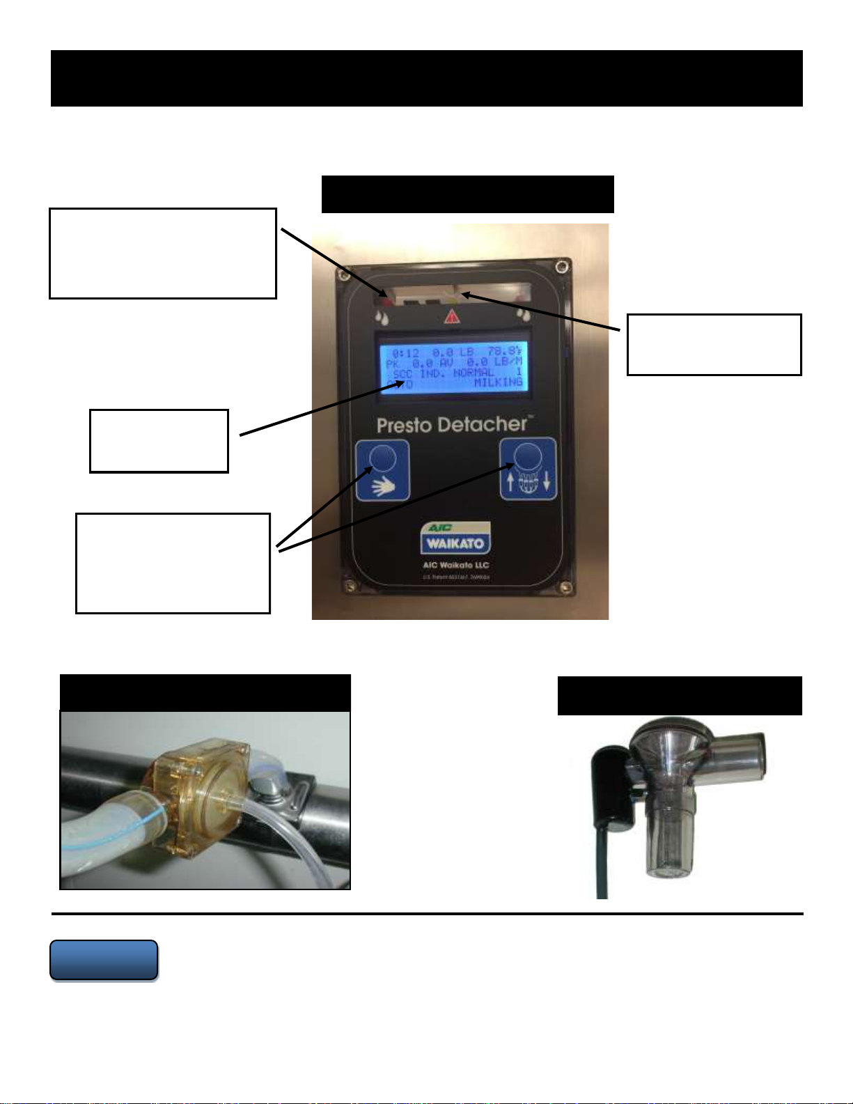
Presto Control Outputs:
‘’
‘’
Power Requirement Calculation:
WARNING
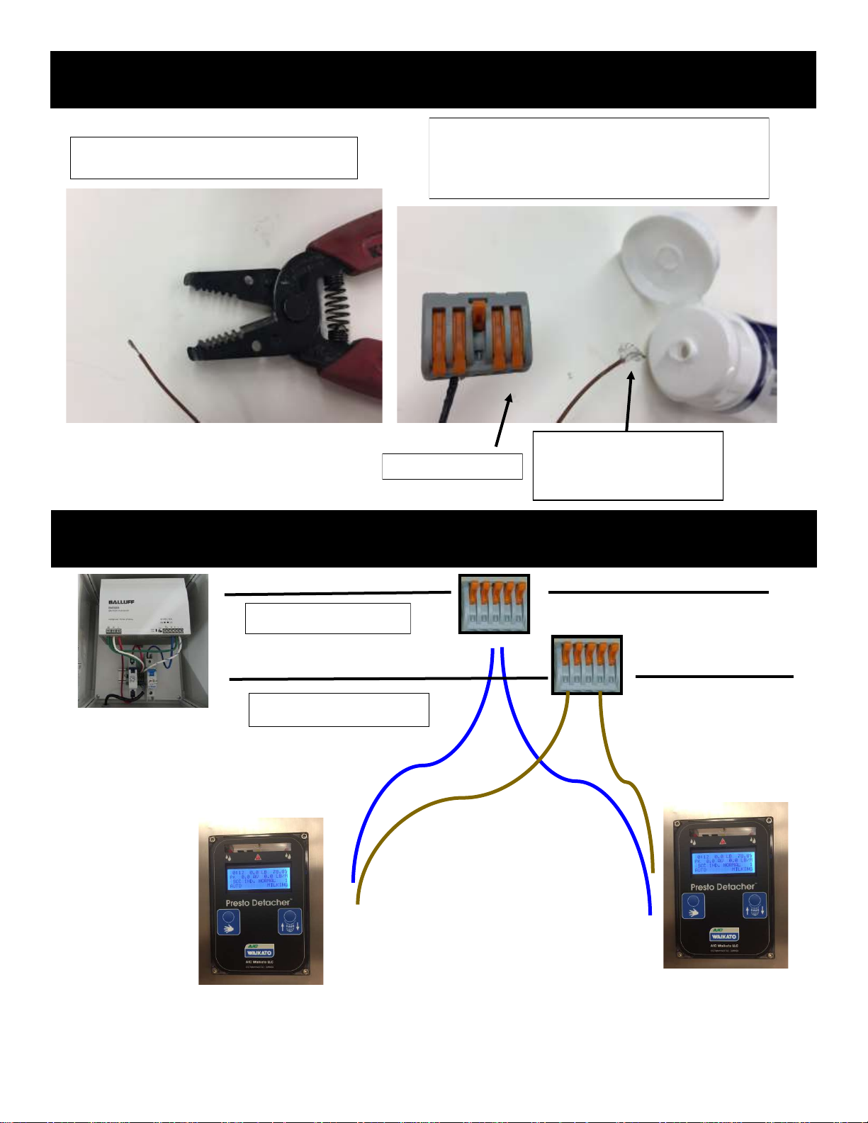
Power Supplies and AC Power Source
In all cases, follow local electrical codes and
safety regulations at all times. It is
recommended the power source be 220/240 volt
and that the power supply be wired to a
dedicated circuit in the incoming power panel.
There should be no additional equipment
hooked to the AC power lines feeding the
power supply. When two or more power
supplies are used in the same installation, the
negative outputs must be tied together by
adding an 14 gauge jumper wire tying the
negative DC outputs together of each power
supply. This establishes a common reference
plane, enabling communications to function.
(When using two power supplies see the
following Parlor Wiring Schematic for more
than 18 stalls)
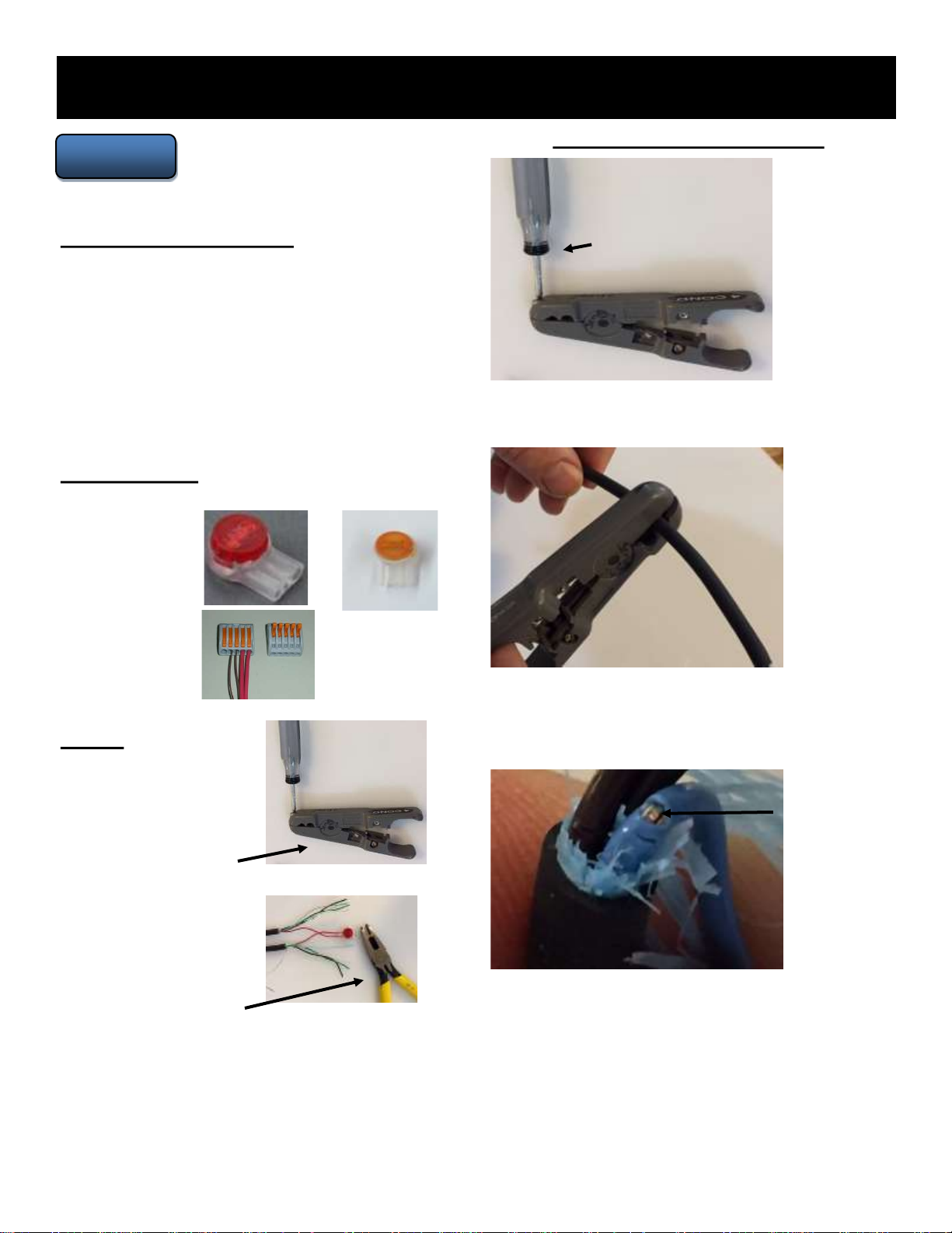
Step 1:
Step 2:
Step 3:
’
Step 4:
CAUTION
Ensure that the existing power supplies are of adequate power rating.
Agricultural Instruments is not responsible for damages or losses
incurred by poorly functioning power supplies. Solid connections are
absolutely necessary to assure no electrical problems will occur.
WARNING