AICSYS RCK-203BE User manual

RCK-203BE
Rackmount Chassis
User Manual

- 2 -
Copyright Notice
This document and product is copyrighted, January 2014, by AICSYS, Inc. All rights are
reserved. No part of this manual may be reproduced, copied, or translated without prior
notice to AICSYS, Inc.
RCK-203BE is trademark of AICSYS, Inc.
Disclaimer:
Specification and information contained in this manual are provided for reference only. We
do not assume any responsibility arising out of the application of the products. This manual
is subject to change without any notice.
January 2014

- 3 -
Table of Contents
Chapter 1 Getting Started ..................................................................... 4
General Information....................................................................................................................4
Product Specification.................................................................................................................4
Packing Checklist .......................................................................................................................4
Recommended Tools .................................................................................................................5
Recommended Working Environment ..................................................................................5
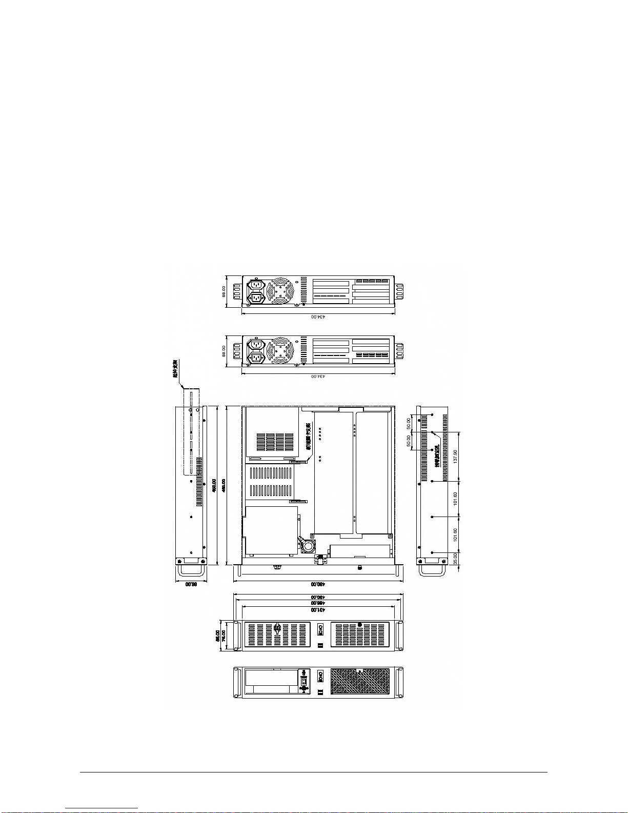
Chassis Mechanical Drawing...................................................................................................5
Chapter 2 Installation Guide ................................................................. 6
Unpacking the Chassis..............................................................................................................6
Removing the top cover............................................................................................................6
Installing the Power Supply Unit.............................................................................................7
Installing the Hard Disk Drive..................................................................................................7
Installing the Backplane............................................................................................................8
Installing the CPU Card .............................................................................................................8
Appendix A Power Supply Unit ........................................................... 9
Appendix B Motherboard................................................................... 9

- 4 -
Chapter 1 Getting Started
General Information
The RCK-203BE Rackmount chassis supports full-size SBC through 2U PICMG1.0/ 1.3
butterfly backplanes, and (1) 5.25", (1) 3.5" external drives, and (1) 3.5" internal drive. The
chassis has (2) 80mm high-speed ball-bearing fans, and supports PS2 power supply.
Product Specification
Construction
Heavy-duty steel
Drive bay
(1) 5.25", (1) 3.5" external drives, and (1) 3.5" internal drive
Cooling fan
(2) 80mm high-speed ball-bearing fans
Switch
On/Off switch and Reset switch
Indicator
Power On/Off,HDD activity LEDs
I/O
(2) USB and (1) PS/2
Expansion
5 x full-height expansion slots
PICMG 1.0 / 1.3 backplanes with PCI or PCIe slot expansion
(refer to Appendix B)
Dimension (W x D x H)
434 x 450 x 88 mm; 17 x 17.7 x 3.5 inches
Weight
NW: 7.4kg / GW: 10.2kg
Packing Checklist
2 x Rackmount bracket
2 x Fasterner adhesive
8 x Rackmount bracket screw set
5 x Fastener
24 x Backplane & FDD & ODD screw
12 x PSU & 3.5”HDD screw
2 x Card hold Bracket
4 x Card hold screw
2 x Key

- 5 -
Recommended Tools
- Philips Head Screwdriver
- Flat Head Screwdriver
- Forceps (for pulling out jumpers and screws)
Recommended Working Environment
A flat anti-static work surface is required when assembling a complete system
Chassis Mechanical Drawing
Drawing with dimension in millimeter:

- 6 -
Chapter 2 Installation Guide
Unpacking the Chassis
The RCK-203BE is shipped in a plastic bag that is placed inside a cardboard box. The
accessories are also shipped with the chassis. When you unpack the chassis you must:
- Make sure all the accessories and components listed above are present.
- Make sure the chassis has not been damaged in anyway. The installation steps outlined
above are described in details below. Please refer to the relevant section(s).
Removing the top cover
The top cover is secured by a total of seven screws (three on each side and one on rear
side).To remove the top cover, please follow the steps below:
1. Remove all seven top cover retention
screws
2. Slide the cover toward rear of the
chassis, then lift the cover off the chassis

- 7 -
Installing the Power Supply Unit
Once the top cover have been removed, a user supplied PSU can be installed. The PSU is
installed at the rear of the chassis and secured to the chassis with four retention screws. To
install the PSU, please follow the steps below:
1. Correctly position the PSU at the
rear of the chassis with the power
switch and cable socket both
facing outwards. Secure the PSU
by inserting four retention screws
through the rear of the chassis
Compatible Power Supply Unit models are available in AppendixA.
Installing the Hard Disk Drive
The RCK-203BE chassis supports one 5.25" and one 3.5”external drives bays. To install
the drives, please follow the steps outlined in the sections below.
1. Remove the four screws and pull upside to
remove the HDD bracket from the chassis
3. For installing 5.25” drive, remove the four
retention screws for each bay as indicated by
red circles. Then insert the drive and secure
retention screws as indicated by black circles.
4. After the 5.25”or 3.5” drives assembled to the
bracket, place back to the chassis, and secure
with crews.
2. For installing 3.5” drive, remove
the four retention screws for
each bay as indicated by blue
circles. Then insert the drive
and secure retention screws as
indicated by green circles

- 8 -
Installing the Backplane
To install the backplane please follow the instructions below:
1. Remove the fours crews securing the
backplane bracket and pull upside to remove
from the chassis
2. Place the backplane to the bracket, and
insert the screw to secure the backplane to
the bracket
4. 鬆開背板支架的四顆螺絲
並向上取出支架
5. 將背板安裝上支架並鎖上螺絲
6.
Different backplane may have different Screw hole positions, please refer to their own
User manual for details.
Compatible backplane models are available in Appendix B.
Installing the CPU Card
To install the CPU Card please follow the instructions below:
1. Remove the rear I/O slot bracket by
removing the screw
3. Place the backplane bracket with CPU
card inside back to the chassis, and secure
with four screws
2. Insert the CPU Card to the backplane
socket and secure with original screw
from I/O slot bracket

- 9 -
Please make sure to disconnect the Power Supply before installing the CPU Card.
Do not turn on power during the CPU card installation
Electrostatic Discharge (ESD) can damage electronic components. To prevent damage
to your system, use a grounded wrist strap designed to prevent static discharge
Appendix A Power Supply Unit
Compatible Power Supply Units are listed in the table below:
Model number
Wattage
Type
Dimension (W x H x L)
SS-400ES
400W
Single output
150 x 140 x 86mm
SS-600ES
600W
Single output
150 x 140 x 86mm
Appendix B Motherboard
Compatible AICSYS motherboards are listed in the table below:
Model number
Type
PCI
PCIe
ISA
BP-0602P-2U
Full-size PICMG 1.0 Backplanes
2
N/A
2
BP-0604P-2U
Full-size PICMG 1.0 Backplanes
4
N/A
N/A
BPE-0502P-2U
Full-size PICMG 1.3 Backplanes
2
2
N/A
BPE-0605E-2U
Full-size PICMG 1.3 Backplanes
N/A
5
N/A

- 10 -
The Global Choice for
Premium Industrial Computer Products
www.aicsys.com
Table of contents
Other AICSYS Chassis manuals