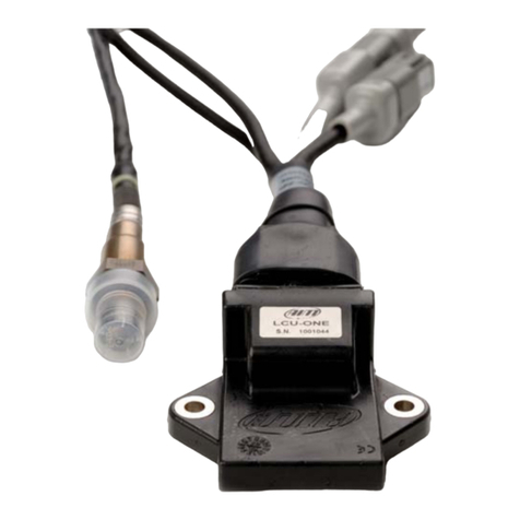
Aim LCU-ONE CAN User manual

1
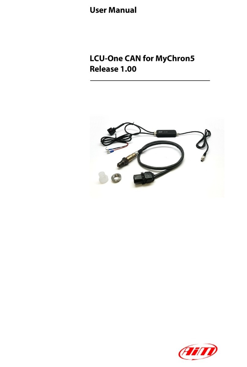
User Manual
LCU-One CAN for AiM loggers
Release 1.00

2
INDEX
1 – LCU-One CAN in a few words 3
2 – The kit contains 3
3 – What is lambda 4
3.1 – Rich mixture 4
3.2 – Lean Mixture 4
3.3 – Stoichiometric mixture 4
3.4 – Bosch LSU 4.9 probe warning 5
4 – Powering LCU-One CAN controller 6
5 – Installing the probe and LCU-One CAN lambda controller 7
6 – LCU-One CAN and AiM devices 8
6.1 – AiM Network 8
6.2 – Configuration of LCU-One CAN 9
6.3 – Configuration issues 11
7 – How to analyse LCU-One CAN data 12
8 – Technical specifications and drawings 14

3
1 – LCU-One CAN in a few words
LCU-One CAN is the lambda controller unit designed to work exclusively with Bosch LSU 4.9 wideband probes, which are the quickest
and most accurate way to analyse exhaust gases and provide a real-time parameter related to engine carburetion.
Lambda probes can be applied to 2 and 4 strokes engines, gasoline, diesel, methane or alcohol-based fuels.
LCU-One CAN communicates with AiM devices via CAN, providing lambda value, Air/Fuel ratio, probe temperature and diagnostics
parameters. An external 12V battery is required, this will supply power to the AiM master unit and the LCU-One CAN, which must be
powered with its power supply leads.
LCU-One CAN is the only CAN connected AiM Lambda Controller compatible with Race Studio 3 supported products.
LCU One CAN+Analog will only communicate through the analog line.
2 – The kit contains
The kit part number is: X08LCU05CAN
It contains:
•LCU-One Lambda controller (1)
•Bosch LSU 4.9 wide band probe (2)
•Weld on bung (3)
Bosch probe and bung can be bought separately as spare parts with these part numbers:
•SSU Bosch 4.9 probe X05LSU490
•Weld on bung LBS552680

4
3 – What is lambda
Lambda represents the ratio between the actual mixture of air/fuel (A/F or AFR) admitted in the engine, compared to the optimum ratio
(A/Fstoichiometric or AFRstoichiometric) indicating an efficient fuel combustion. Lambda can be written as:
=
/
/ℎ =
ℎ
where:
A= parts of air (oxygen) in the combustion chamber
F= parts of fuel in the combustion chamber
To completely burn one part of gasoline, 14.57 parts of air (AFRstoichiometric) are required.
This optimal combustion is also indicated as Lambda = 1, whatever is the fuel in use.
AFRstoichiometric is a fuel dependant constant. Oxygenated fuels and additives will change this value, thus it is strongly recommended to use
Lambda as reference parameter.
3.1 – Rich mixture
If the actual mixture has less than 14.57 air parts to 1 part of gasoline, the mixture is said rich.
For example An AFR of 12.2 is a rich mixture and is also indicated as:
84.0
57.14
2.12 ==Lambda
Lambda < 1
AFR < 14.57 (for gasoline)
3.2 – Lean Mixture
If the actual mixture has more than 14.57 air parts to 1 part of gasoline, the mixture is said lean.
For example an AFR of 17.5 is a lean mixture and is also indicated as:
2.1
57.14
5.17 ==Lambda
Lambda > 1
AFR > 14.57 (for gasoline)
3.3 – Stoichiometric mixture
If the actual mixture has 14.57 air parts to 1 part of gasoline, the mixture is in the stoichiometric ratio.This is also indicated as Lambda = 1

5
3.4 – Bosch LSU 4.9 probe warning
Bosch LSU 4.9 is a wideband lambda probe which does not require any specific calibration procedure, it auto-calibrates on a reference
electrical current which guarantees the same performance over time.
When in use the probe becomes very hot (700-800 °C or 1291-1472 °F), so do not touch it or place it in contact with inflammable material
or fuel.
Warning: misuse can cause shocks, burnings or explosions.
Do not clean the probe with solvents or additives, pay attention when cleaning vehicles with exposed engines, to avoid detergent
pollution.
Never switch the engine on, if the probe is installed but not connected to a working controller LCU-One CAN. If a probe were to be exposed
to exhaust gas, when not heated, it would be permanently damaged. Wait for the probe to be ready, you will read the following values on
the dash (Lambda = 1.6 or AFR = 23.31) depending on your display set up.
•during warmup – left image – Lambda value is 1 (14.56 AFR)
•when the probe is ready – right image – Lambda value with the engine off is 1.60 (free air) (23.31 AFR).
The LCU One with Bosch LSU 4.9 detects Lambda values in a 0.6 – 1.6 range (9.5 – 23.3 AFR).

6
4 – Powering LCU-One CAN controller
The wideband Lambda probe has a working temperature of about 780°C (1436°F); for this reason it is constantly monitored by the Lambda
controller LCU-One CAN, that tunes the power supplied by an external 12V battery.
The warm-up can drain up to 1.6A while the average consumption is approximately 1A, thus if the vehicle doesn’t have an alternator, it is
recommended to install a battery that can last several hours feeding the whole logging system. A 4 cells LiPo battery with a capacity of
3000mAh, for example, can guarantee 3 hours of activity.
LCU-One CAN controller has to be connected directly to the external 12V battery, using the three leads (one red and two black) supplied
with spade connectors. They all have to be correctly connected with no dispersions, bad crimping, oxide or thin section wires causing an
inadequate current supply to warm-up the Lambda probe. These are the most common causes of bad reading and premature poisoning
of Lambda probes.
The addition of a protection fuse (i.e 5A) is suggested, and if a switch is added, make sure it can comply with the electrical current rates
indicated above.

7
5 – Installing the probe and LCU-One CAN lambda controller
Bosch LSU 4.9 Lambda probe must be installed on the exhaust pipe welding the bung supplied with the kit or using an existing thread.
Install the probe close to the engine, avoiding its cable to be in contact with heat sources and the pipe.
The probe working temperature must not exceed 900°C (1652°F) nor be exposed to the free flame coming out of the engine. The lambda
sensor should be installed at a point that permits the measurement of a representative exhaust-gas mixture, which does not exceed the
maximum permissible temperature but is as hot as possible.
It is recommended to install the sensor vertically (wire upwards), this will protect the sensor against condensation water; should this not
be possible, maintain a minimum of 10 degrees of tilt (right image below).
The sensor is not to be fitted near to the exhaust pipe outlet, so that the influence of the outside air can be ruled out. The exhaust-gas
passage opposite the sensor, must be free of leaks to avoid the effects of leak-air.
Install the LCU-One CAN module adopting anti vibrating devices, like rawl nuts or neoprene mats. The module carries two M3x10mm
fixing holes. Avoid the module to be exposed to high temperatures, this must not be placed in proximity of the exhaust pipe, if the module
has to be located in the engine bay, choose a vented position far from heat parts.

8
6 – LCU-One CAN and AiM devices
The LCU-One CAN is totally integrated with AiM devices, its connection to the AiM CAN network and the display setup allows to have
everything under control on the master unit display or in the logged data.
6.1 – AiM Network
You can connect LCU-One CAN directly to the “Exp” connector or add it to an extended network as shown here below.
Please note: all devices are to be connected when switched off. The master logger automatically detects LCU-One CAN and all other
expansions at startup, provided that they have been set with Race Studio 3 – Configuration software , as explained in the next chapter.

9
6.2 – Configuration of LCU-One CAN
To set one or more LCU-One CAN modules connected to the AiM master unit, run Race Studio 3 configuration software and follow the
steps here described.
•Open an existing configuration or create a new one.
•Select CAN Expansions tab
•Press New Expansion button; the panel here on below is prompted
•Select LCU-One CAN and press OK
•Name the LCU-One and fill in its serial number or press Get Serial Number to read it directly from a connected expansion.
•It is possible to choose from several preset values of AFRstoichiometricor add custom values using the two buttons in the middle of
the window. If no action is taken here, the default value of 14.57 AFR (gasoline) is used.
•From the lower panel it is possible to enable/disable the management of its 4 channels. It is also possible to modify the recording
frequency and the number of decimals to use.
•Once finished, press Close and the setting is saved.
•To add other Lambda controllers press the New Expansion button and repeat the steps.
•Transmit the configuration to the AiM logger for the modifications to take effect.

10
To display LCU-One CAN parameters on the display
•Select Display tab
•Add a new page or modify an existing one selecting it from the list on the right.
•Select the field you wish the Lambda parameter to be shown. The panel below is prompted.
•The source to select is LCU-One CAN Exp.
•The list of the available channel depends on the number of LCUOne CAN modules installed.
•Select the information to be displayed and confirm pressing OK
•For additional parameters repeat from the field selection or open/modify another page.
•Transmit the configuration to the AiM logger for the modifications to take effect.

11
6.3 – Configuration issues
Should any connection issue arise, make sure that LCU-One CAN is correctly connected to the master unit. After having inspected its power
supply cables and when the CAN connection cable is correctly plugged in the EXP port, check the connectivity using Race Studio 3
following these steps:
•Connect your AiM master unit and run Race Studio 3 software.
•Press Devices and select yours in Connected Devices label.
•On the main panel on the right, select the Firmware tab and check if the LCU-One CAN is listed (see image).
•If available, make sure the configuration is correctly set and transmitted to the main AiM device.
An alternative way to check if the LCU-One CAN is correctly recognized is to use the AIM display: access the Menu – System Info – Net Info

12
7 – How to analyse LCU-One CAN data
Once the session is over and data have been downloaded from the AiM master logger, you can analyse them using Race Studio Analysis
software.
Running the software and opening the test you will see that
LCU-One CAN connection adds four channels to “Measures and
laps” bar (image on the right):
•Lambda Val: shows Lambda value recorded during the
test
•Lambda AFR: shows the stoichiometric value of the
fuel in use
•Lambda_Temp: shows the working probe internal
temperature
•Lambda Diagn: shows the probe status; values that
can be shown are:
0 = ok
1 = probe disconnected from controller and
circuit open
2 = 12V short circuit
3 = GND short circuit
Documents and tutorials relevant to LCU-One and Lambda
analysis are available at:
www.aim-sportline.com – Documentation area – On-Track
sessions.

13
The image below shows a view of Race Studio Analysis 3 including Lambda figures.

14
8 – Technical specifications and drawings
•Dimensions 87,6x39x15.5 mm [3.44x0.53x0.61 inches]
•Waterproof IP67

15
Our website www.aim-sportline.com is constantly updated. Please refer to it for updates on firmware, software and documentation.
Other manuals for LCU-ONE CAN
2
This manual suits for next models
1
Table of contents
Other Aim Controllers manuals