Aimco UTM-1500 User manual

PO Box 16460, Portlan OR 97292-0460 • 800-852-1368 • Fax 800-582-9015
www.aimco-global.com
Fastening Counter
UTM – 1500
Instruction Manual
(Software Version 1.06)

2
Table of Contents
Safety Precautions ................................................................................................................................................. 3
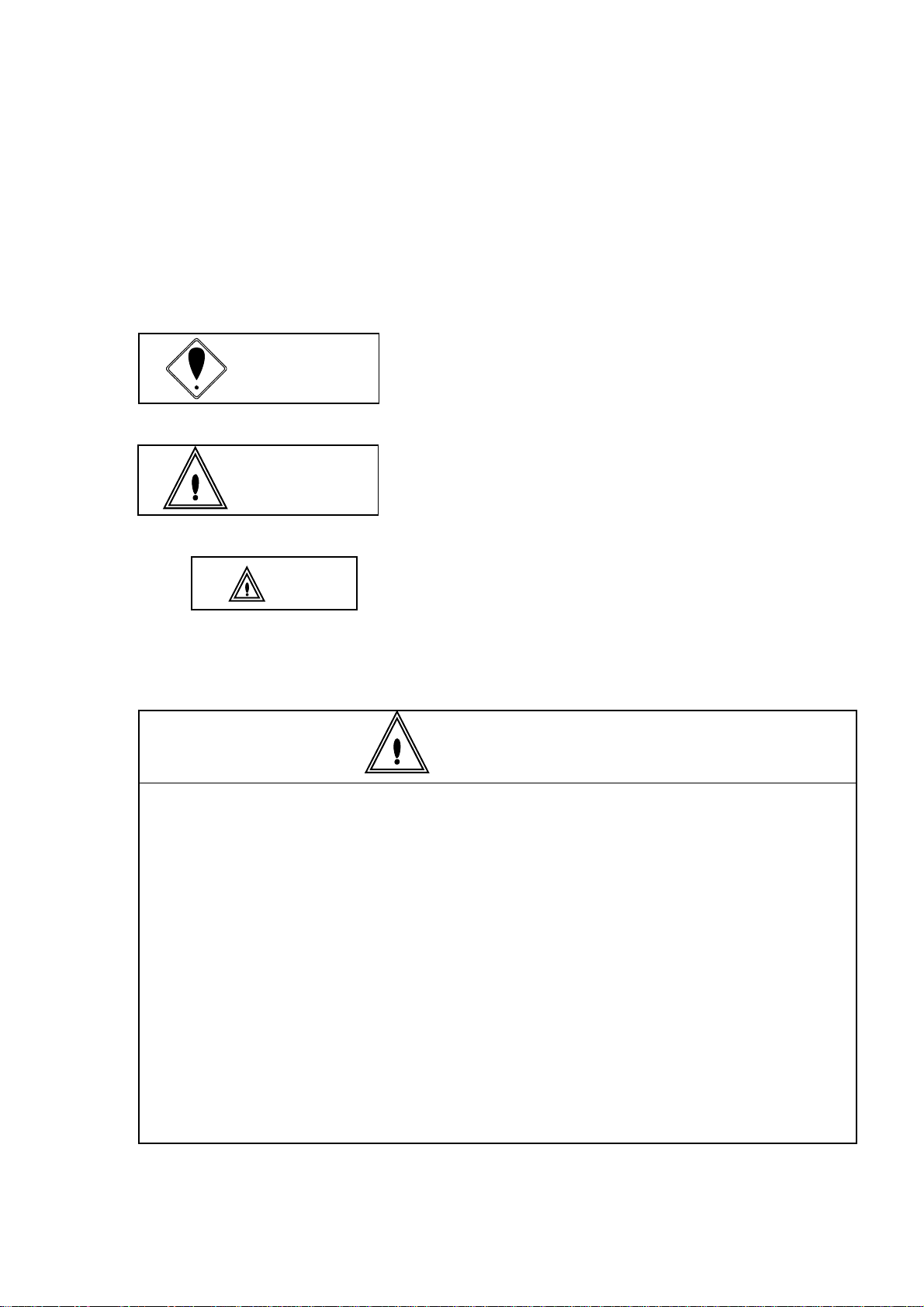
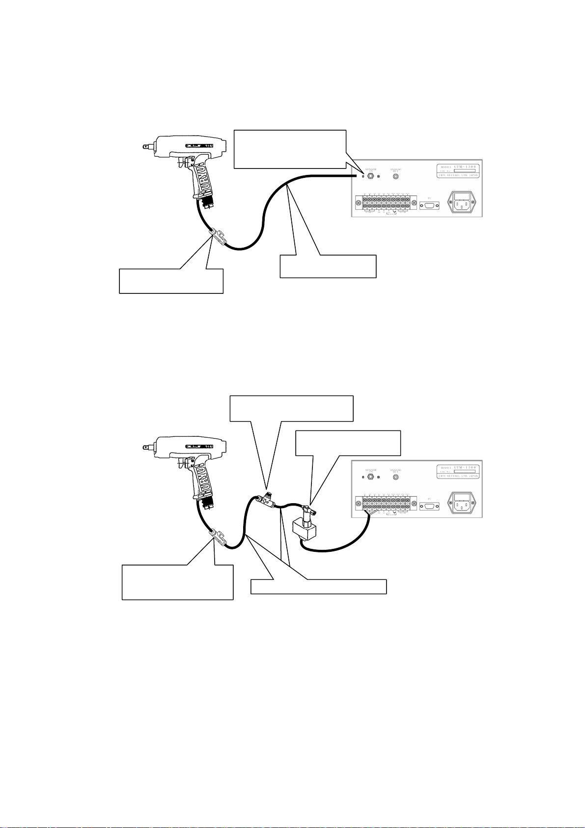
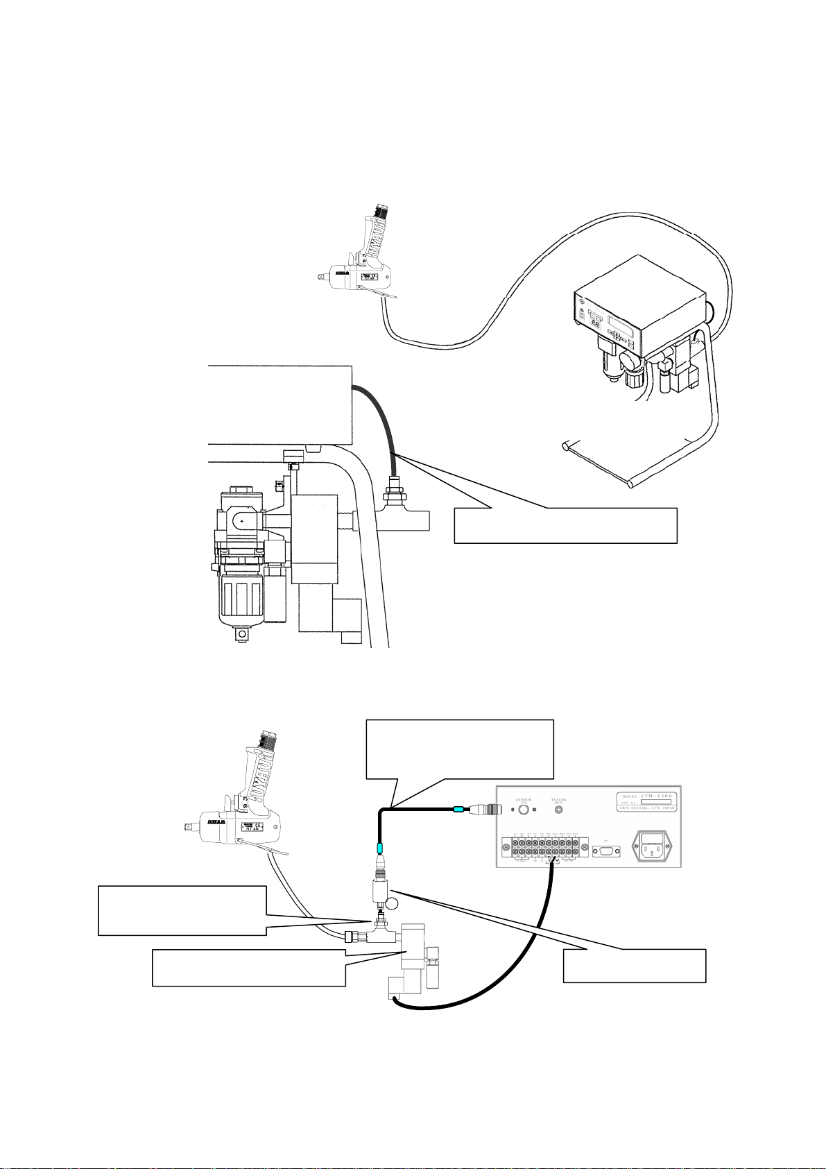
(1) Shut-off Tool (TM)..................................................................................................................................7
Exterior Features................................................................................................................................................. 11
(1) Front Side.............................................................................................................................................11
(2) Back Side..............................................................................................................................................13
Functions.............................................................................................................................................................. 14
Settings................................................................................................................................................................. 15
SET UP............................................................................................................................................................... 16
AUTOMATIC SET UP (automatic setting) ........................................................................................................ 25
TIMER .................................................................................................................................................................. 26
TERMINAL ALLOCATION(Terminal Block Input/Output Alternatives)................................................... 28
(1) Choice among terminal block input alternatives.......................................................................................28
(1) Choice among terminal block output alternatives.....................................................................................29
WIRING DIAGNOSIS(Terminal Block Wiring Diagnosis)........................................................................... 30
(1) Input Wiring Diagnosis .......................................................................................................................30
(2) Output Wiring Diagnosis ....................................................................................................................30
MEMORY........................................................................................................................................................... 31
BAUD RATE(transmission speed)............................................................................................................... 31
Tool Management(tool management)........................................................................................................... 32
(1) TOOL........................................................................................................................................................32
( 2 ) OUT SET.........................................................................................................................................32
( 3 ) CUMULATIVE COUNT .................................................................................................................34
Pressure Value Setting ........................................................................................................................................ 35
( 1 ) In the case of Shut-off Tool (TM).........................................................................................................35
( 2 ) In the case of TM Type Tool ................................................................................................................35
( 3 ) In the case of Standard Tool................................................................................................................35

3
Safety Precautions
You should first read this manual thoroughly and become familiar with this System
and safety precautions before installing, operating, servicing and inspecting it.
Take note that two different signs; “DANGER” and “CAUTION”, are used in this
Manual according to the degree of seriousness and urgency.
CAUTION signs also warn the risk of serious consequences depending
on the situation. So, always follow the instructions given in this Manual.
DANGER .A fatality and/or heavy personal injury is highly possible by
misoperation. Urgent warning is essential in the event of an accident.
:
◆Installation & Surroundings
CAUTION
●Always attach to a metal or other incombustible component to prevent a fire.
●Keep away from combustibles to prevent a fire.
●Avoid foreign matter intrusion to prevent a fire.
●Set up Controller on a site that can bear its weight to avoid personal injury from
accidental falling.
●Keep your workplace well lighted and clean to avoid personal injury.
●Never wear loose-fitting clothes or dangling jewelry when using this System, and always
wear the right clothes suitable for your job. In addition, be careful not to get your hair
caught in tools, and if you wear your hair long, always tie with a rubber ribbon or the like
and wear a protective helmet to prevent personal injury.
●Securely install and fix this System to avoid personal injury in case of an emergency like
an earthquake.
CAUTION
A dangerous situation accompanying mid-slight personal injury and/or
property damage is possible by misoperation.
:

4
Danger
◆Wiring
●Be sure to turn OFF the mains prior to wiring to avoid an electric shock or a fire.
●Make sure that cords and outlets are properly grounded to avoid an electric shock or a
fire.
●Carry out wiring after you installed Controller to avoid an electric shock or a fire.
●Wiring must be carried out by an expert electrician to avoid an electric shock or a fire.
●Always use Y-shape or round crimp terminals when wiring Terminal Block to avoid an
electric shock or a fire.
Caution
Danger
◆Handling/Operation
●Assurance of work-site safety by operators themselves prior to power switching operation
is essential to prevent personal injury.
●Never touch switching devices with moistened hands to avoid an electric shock.
●Avoid touching the terminals of current-carrying Controller even during Tool is under
non-operating conditions to avoid an electric shock.
●Avoid damage, mechanical stress, load to cords and never tuck them in forcibly to avoid an
electric shock.
●Be sure to turn OFF the mains after each use.
●Be sure that Controller rated voltage agrees with AC power source to avoid personal injury
and a possible fire.
●Wires must be routed and fixed properly and securely to avoid personal injury and a fire.

5
Caution
●Make settings within the confines of the prescribed operating range to avoid personal injury and burns.
●Perform operations in safe surroundings while keeping proper footing. Avoid poor postures to prevent
danger.
●Perform operations with extra care. Operations in a careless and inappropriate manner and/or
lon
g
-duration o
p
eration is
p
rohibited to avoid
p
ersonal in
j
ur
y
or work-related diseases.
◆Maintenance/Servicing
Danger
●Turn off and unplug the mains prior to inspection/replacement to avoid an electric shock.
●Maintenance/servicing works only by an expert is allowed. Be sure to take off metal
articles (wrist-watch or ring) prior to operation. Inspect cords periodically for damage,
and have an expert make repairs or exchange if signs of wear is noticed. Always use
insulating tools at the time of servicing to avoid an electric shock and personal injury.
●Always order us or our designated agent when overhauling becomes necessary to avoid an
electric shock, personal injury and fire.
◆Disposal
Danger
●Never add modifications to your System to avoid an electric shock, injury or fire.
●Stop your System right away and cut off the power whenever something unusual occurs.
●Keep persons irrelevant to System operation away from work-sites.
General Precautions
●Dispose of your System as an industrial waste.
◆Others
Caution

6
Specifications
Items Particulars
Power Source AC100~240V±10% adaptable
Power
Consumption
40VA
Outer Dimension 210 (W) x 100 (H) x 200 (D) mm
Weight Connector Type: about 2.03 kg
Pressure Sensor On-board Type: about 2.05 kg
2-digit digital display
Indication:Remaining count number (“WORK No.” at the time of setting
value inputting)
Display LCD 20 characters×4lines
Indication:Setting value, pressure value, alarm message, judgment,
fastening time, pulse number
Lamp Fastening number judgment: OK (green)/NOK (red), Size 14x14
Buzzer High-tone electronic buzzer. Buzzer currently used in UTM-1100 is
interchangeable.
Front Panel Key Switch
Setting Method PC (use our original software)
Terminal Block Input: 6 points, Output: 5 points
20P detachable type(Sato Parts ML-100-AS-20)
Pressure Signal
Input
Connection with the pressure sensor incorporated in Tool via the
connector at the back allows power supply and analog signal input.
Analog Output Plug Size: JISC6560 (small, single-head plug φ3.5x15)
Major Functions
Fastening number control
Fastening time control
Pulse number control ※1
Various judgments
Others
Two types of controllers are available, one is pressure sensor
incorporated type and the other is connector incorporated type as follows:
Pressure Sensor Incorporated Type : UTM-1500 (PS)
Connector Incorporated Type : UTM-1500 (CN)
※1:For pulse detection, prepare a 30cm-long or shorter TM Signal hose to connect Tool and
Pressure Sensor.
There are times when pulse detection is impossible in the case that a less pneumatic
pressure fluctuation type tool (like a small tool) is in use and/or depending on the work
conditions.

7
Tool Connection
・Make the length of TM Signal air hose between Tool and Pressure Sensor (external pressure
sensor/main body incorporated sensor) or Air-electric Relay as short as possible. A lengthy air
hose may sometimes cause a delay in detecting pneumatic pressure fluctuations or hinder
correct detection. (Shorter than 5m is recommended)
・In the case of fastening pulse number detection, the length of TM Signal air hose between Tool
and Pressure Sensor must be maintained shorter than 30cm. TM Signal air hose of longer
than 30cm will interfere with air pulsation taking during pulsing.
・When using TM Tool or Standard Tool, place Solenoid Valve at an adequate point so as the length
of the air hose up to Tool will be maintained as short as possible. When the air hose between
Solenoid Valve and Tool is unnecessary lengthy, Tool stop timing will be delayed due to
residual pressure in the hose even though the valve reacted normally.
(1)Shut-off Tool (TM)
①When using UTM-1500(CN) and External Pressure Sensor Assembly
・Place External Pressure Sensor Assembly as close as possible to Tool.
②When using UTM-1500 (RA-CN)
・Same wiring as in the case of without a rack (①).
Connector incorporated, with-a-rack
type UTM-1500 (RA-CN)
Pressure Sensor Cable Assembly (5m)
(Part Code:910-820-0)
Pressure Sensor Cable Assembly (10m)
(Part Code:910-821-0)
Hook up Sensor Cable to
Connector at Controller’s back
External Pressure Sensor
Assembly(Part Code:878-845-1)
TM Signal Air Hose
Connector Incorporated
Type UTM-1500 (CN)

8
③When using UTM-1500 (PS)
④When using Air-electric Relay
・Place Speed Controller when using Air-electric Relay.
・Both UTM-1500 (CN) and UTM-1500 (PS) are acceptable.
・Allocate PS to Input Terminal Block and hook up the cable from Air-electric Relay.
Hose joint, or
Quick exhaust
Attach TM Signal air hose to
Coupler at the controller’s
back
Pressure Sensor Incorporated
Type UTM-1500 (PS)
Polyurethane tube
TP-4
Quick exhaust
AQ240F-04-00
(Part Code: 909-442-0)
Air-electric Relay Assembly
(Part Code:909-851-0)
Speed Controller AS100F-04
(Part Code:909-449-0)
UTM-1500
(CN) or (PS)
ポリウ
Polyurethane tube:TP-4

9
(2)TM Type Tool
①When using UTM-1500 (RA-CN)
②In the case of without a rack
→Main Piping
+24V
0V
Solenoid Valve CP (VP542)
(Part Code:909-749-0)
Polyurethane tube:TP-4
Connector incorporated, with-a-rack type
UTM-1500 (RA-CN)
External Pressure Sensor Assembly
(Part Code:878-845-1)
Pressure Sensor Cable Assembly (5m)
(Part Code:910-820-0)
Pressure Sensor Cable Assembly (10m)
(Part Code: 910-821-0)

10
(3)Standard Tool
①When using UTM-1500 (RA-PS)
②When using UTM-1500 (CN)
Pressure sensor incorporated, with-a-rack
type UTM-1500 (RA-PS)
Solenoid Valve Assembly (VP542)
(Part Code:909-749-0)
Air pressure signal output from Solenoid
Valve’s back goes to Pressure Sensor
Air pressure signal output
from Solenoid Valve’s back
goes to Pressure Sensor
External Pressure Sensor
Assembly (Part Code:878-845-1)
Pressure Sensor Cable Assembly (5m)
(Part Code:910-820-0)
Pressure Sensor Cable Assembly (10m)
(Part Code:910-821-0)

11
Exterior Features
(1)Front Side
①Power Switch
|:ON
○:OFF
②Power Lamp(green)
The green LED lamp lights up when the power switch is turned ON.
③Buzzer
The volume of fastening recognition, NOK and Key Operation sound can be adjusted each
independently.
Low-tone buzzer can also be used alternatively. (Always use the low-tone buzzer at the
maximum 5 volume setting as the buzzer does not produce audible sound with low
settings.)
Part Name:Low-tone buzzer unit (Star PMB-06)
Part Number:910-824-0
④Judgment Lamp
Count OK : OK lamp will light up.
Count NOK : NOK lamp will light up.
Fastening OK : Lamps remain off.
Fastening NOK : NOK lamp will flash.
During MENU screen operation : OK and NOK lamps will light up by turns.
OK NOK
JUDGE
1
2
3
5
4
6
7

12
⑤2-digit, 7-segment LED Display
Remaining fastening number will be indicated.
(”WORK No.” will be indicated if “on a WORK No. basis setting” has been specified on
MENU screen.)
⑥LCD (20-digit x 4 lines) Display
【During measurement】
First Line : Selected WORK No.
Second Line : P1, P2 monitor indication. Blow start, shut-off detecting status will be
indicated. ○means “detecting” and ●means “not detecting”.
TOOL TYPE
SHUT-OFF
(ULT or other shut-off
tools)
TM
(TM Type Tool)
NON-SHUT
(Standard Tool)
P1 BLOW START
Blow start
LEVER ON
Lever “ON”
P2 SHUT-OFF
Shut-off
BLOW START
Blow start
P1:Pressure at Blow start detection monitor
P2:Pressure at Shut-off detection monitor
Third Line : Pressure value monitor
Fourth Line : “Judge”, “Fastening Time”, “Pulse Number.”
Judgment:Judgment related to fastening operation including OK, PLS. LOW, NOK)
Fastening Time:Time interval between blow start and shut-off
Pulse No.:Blow number from blow start to shut-off in the case of Shut-off Tool.
Blow number during ON timer is in action in the case of TM Tool/Standard
Tool.
※There are times when pulse detection is impossible depending on Tool types
and/or working conditions.
⑦Key Switch(for MENU selection and setting value entry)
WORK No.1
P1:● P2:○
P.VALUE: 0.35MPa
OK 1000msec 10PLS

13
(2)Back Side
①Terminal Block(detachable)
Wiring to Input Terminal must be under no-voltage conditions.
Wiring to Output Terminal must be less than DC24V.
Always use Y-shape or round crimp-style terminals when wiring.
②Sensor Cable coupling connector (Pressure Sensor can be installed with the connector removed.)
③ANALOG OUT
Analog signals will be output from Pressure Sensor.
④PC Connector
Hook up the cable from PC.
⑤Power cable connector
⑥Fuse (spare fuse incorporated)
1
23
4 5
6

14
Functions
Self-Diagnosis Function
Self-diagnosis function will run in the main system at power-on.
Software version will be displayed on the second line of LCD display during self-diagnosis.
Memory Function
Up to 1,500 fastening data can be saved.
Zero Adjustment
There are cases where sensor output voltage shows a bit different voltage from 0V even though the
pressure sensor is under free of pressure conditions. To rectify such deviation, output voltage
under no pressure equals 0.0Mpa equation will be memorized through this function.
Procedure:
・Press +.
Initialization Function
This function will bring System back into factory default settings by initializing old settings and
by erasing memory data saved.
Procedure:
・Turn the power on while pressing +.
7-segment LCD Display - Indicator Lamp Test
7-segment indicator lamps will all light up. 7-segment will turn to “8.8.” and LCD display will
be painted black.
・Turn the power on while pressing key.
Terminal Block Wiring Check Function(P30)
This function is specifically designed to test the terminal block for correct wiring and to see if it is
functioning normally.
Input wiring diagnosis:Input signals can be checked.
Output wiring diagnosis:Output signals can be checked.
UTM-1500
Ver.1.04
URYU
Self-Diagnosis

15
Settings
Self-diagnosis function will run at power-on. Operation Mode will start when no faulty condition
has been detected during the course of Self-diagnosis. Pressing for more than 3 seconds
under Operation Mode will start MENU screen and then Program Mode will be initiated. You
may change setting values under Program Mode. Note that Program Mode will render TM Tool
or Standard Tool uncontrollable. Consequently, Valve Output will turn into ON status and you
may not use Tool during Program Mode.
Press to return to Operation Mode.
JUDGE OK and NOK lamps will light up by turns under Program Mode.
・Select any item by touching .
・The current selection accompanies ■mark on the left.
・Touch to move to the corresponding Screen.
* * * MENU * * *
■SET UP
AUTOMATIC SET UP
TIMER
TERMINAL ALLOCATION
WIRING DIAGNOSIS
MEMORY
BAUD RATE
Tool management

16
SET UP
Function Setting
TOOL(Tool Selection)
Initial Setting:SHUT-OFF TYPE
Select any among three selectable tools; SHUT-OFF TYPE/TM TYPE/NON-
SHUT TYPE
・This selection is common among WORK №1~4.
SHUT-OFF TYPE(Shut-off Tool)
・Tool will stop operation automatically upon completing bolt fastening operation, and then TM
Signal will be output.
・When SHUT-OFF TYPE is selected, ON (Valve ON Timer) and OFF (Valve OFF Timer) initial
values will become “0” respectively.
TM TYPE(TM Type Tool)
・TM Signal will be output during fastening operation. Tool will not stop operation
automatically, and fastening time controlling via UTM will become necessary.
・When Shut-off Tool is selected, Valve ON Timer and Valve OFF Timer initial values will
become “700” and “800” respectively.
NON-SHUT TYPE(Standard Tool)
・As TM Signal will not be output in this case, Tool Blow Start will be sensed using Tool’s hand
pressure. Tool will not stop operation automatically, and fastening time controlling via UTM
will become necessary.
・When Standard Tool is selected, ON and OFF initial values will become “700” and “800”
respectively.
SENSOR(Pressure Sensor Input Type)
Initial Setting:NO DISPLAY
Select any among three selections; NO DISPLAY/DISPLAY/RELAY BOX
・This selection is common among WORK №1~4.
NO DISPLAY:Private external Pressure Sensor Assembly. Sensor incorporated in Tool
or Controller.
DISPLAY:Pressure sensor with a digital display
RELAY BOX:Select when you use Air-electric Relay (without using Pressure Sensor).
* * * SET UP * * *
TOOL: SHUT-OFF TYPE
SENSOR : NO DISPLAY
BLOW START:0.10 MPa
SHUT-OFF: 0.30 MPa
PULSE LV: 0.000 MPa
CUT PULSE No.: 0
UPPER PULSE No.: 0
LOW PULSE No.: 0
■COUNT: 99
L.CONT.:LS1
W.SEL.TIMING: NO
ERROR: REFASTENING
CHECK BZ VOL.: 5
NOK BZ VOL. : 5
KEY BZ VOL. : 5
DISPLAY : Standard

17
BLOW START/LEVER ON [Mpa](Blow Start Pressure/ Fastening Start Pressure)
・Measurement Start Pressure
Initial Value Shut-off Tool : 0.10
TMTypeTool :0.10
Standard Tool : 0.50
Setting Range 0.00~1.00
・When using Shut-off Tool, the corresponding name will be BLOW START, and set a pressure
value to effect Tool blow detection.
・When using TM Tool (not Shut-off) or Standard Tool, the corresponding name will be LEVER ON,
and set a pressure value to effect Tool free-running detection.
・This setting is common among WORK No. 1~4.
SHUT-OFF/BLOW START [Mpa] (Shut-off Pressure/Blow Start Pressure)
Initial Value Shut-off Tool : 0.30
TM Type Tool : 0.20
Standard Tool : 0.30
Setting Range: 0.00~1.00
・When using Shut-off Tool, the corresponding name will be SHUT-OFF, and set a pressure value
to effect Tool Shut-off signal detection.
・When using TM Type or Standard Tool, the corresponding name will be BLOW START, and set a
pressure value to effect Tool blow detection.
・This setting is common among WORK No. 1~4.
PULSE LV [Mpa] (Pulse Detection Pressure)
Setting Range : 0.000~1.000
Initial Value : 0.000
・This is a setting to enable pulse detection.
・PULSE Pulses of less than PULSE LV will not be counted.
・Perform setting works under Auto Setting or by referring to waveforms saved on PC.
・This setting is common among WORK No. 1~4.
※Pulse detection will sometimes become impossible in the case that Tool of less pneumatic
pressure fluctuation type at pulsation (small tool or the like to be more specific) is in use or
depending on work conditions.
CUT PULSE No. (Cut Pulse Number)
Setting Range : 0~999
Initial Value : 0
・In the case of 1~999 setting, Valve Output will take place when the pulse number input reached
the preset pulse number to stop Tool.
・In the event that you do not use this function, make this setting 0.
・This setting is common among WORK No. 1~4.

18
UPPER PULSE No. (Upper Pulse Number)
Setting Range : 0~999
Initial Value : 0
・This is the upper limit for pulse number judgment. When the pulse number measured stepped
across the preset number, Pulse HIGH NOK will result.
・This setting is common among WORK No. 1~4.
・In the case of 0 setting, pulse number upper limit judgment will not be performed.
Reaction in the case of Pulse HIGH NOK detection:
・LCD Display : [Pulse High Error]
・Buzzer : ON
・Output Terminal : FAS. NOK will be output
Error Condition Resetting
・In the case that ERROR (refastening at fastening NOK) is set to REFASTENING (fastening
NOK clear at refastening operation start), the next fastening operation will reset error
conditions:
・RESET key operation or RESET terminal input.
LOW PULSE No. (Lower Pulse Number)
Setting Range : 0~999
Initial Value : 0
・This is the lower limit for pulse number judgment When Tool becomes shut-off condition before
the pulse number measured reached the preset number, Pulse LOW NOK will result.
・This setting is common among WORK No. 1~4.
・In the case of 0 setting, pulse number lower limit judgment will not be performed.
Reaction in the case of Pulse LOW NOK detection:
・LCD Display : [Pulse Low Error]
・Buzzer : ON
・Output Terminal : FAS. NOK will be output
Error Condition Resetting
・In the case that ERROR (refastening at fastening NOK) is set to REFASTENING (fastening
NOK clear at refastening operation start), the next fastening operation will reset error
conditions:
・RESET key operation or RESET terminal input.
COUNT (Fastening Number)
Initial Value : 99
Setting Range : 0~99
・Set intended fastening number.
・This is on a WORK No. basis setting.

19
L. CONTR. (Fastening Number Count Operation Mode Selections)
Initial Setting : LS1
・Select Line Control Mode to be used during Fastening Number Count.
・This setting is common among WORK No. 1~4.
・Note that QL Terminal accepts inputs outside the operating range particularly specified using
this function.
LS1
・All-the-time fastening number counting down ready condition will be rendered, and judgment
will be made on Limit Switch input. COUNT OK judgment will be given when the preset
fastening COUNT number is attained, and ready-to-start the next work fastening operation
status will be brought about when LS1 has been input and the old fastening number has been
cleared. If the preset fastening number is not attained at the time of LS1 input, COUNT
NOK judgment will be given. In this case, COUNT OK judgment will result when the
remaining fastening operation has been completed.
Work
Work Flow
LS1
Operating range
NOK handling range

20
LS1・LS2
・Fastening operation range will be defined. Operation will start (counting down ready
condition) on LS1 input.
・When the preset fastening number is attained before LS2 input, fastening operation will finish.
・COUNT NOK judgment will be given when the preset fastening number is not attained at the
time of LS2 input, and in this case, fastening operation will finish when COUNT OK
condition resulted through NG handling operation.
LS1・LS3・LS2
・Fastening operation range will be defined. Operation will start (counting down ready
condition) on LS1 input. COUNT NOK judgment will be given when the preset fastening
number is not attained at the time of LS3 input, and in this case, the range up to LS2 input
ON will become NG handling range. Fastening operation will finish at the time of LS2 input.
Work
Work Flow
LS2
Operating range
NOK handling range
LS1
Work
Work flow
LS3
Operating range
NOK handling range
LS1 LS2
Table of contents
Popular Cash Counter manuals by other brands

Seedburo
Seedburo Count-A-Pak 801 Operating and service manual

Wincor Nixdorf
Wincor Nixdorf iCASH 15 Cleaning Instruction Guide

PASCO
PASCO PASPort PS-2117 instruction sheet

Kobold
Kobold ZOK-ZxP operating manual

Hach Ultra
Hach Ultra MET ONE 227 user manual

Royal Sovereign
Royal Sovereign RBC-1003 Specifications