Toro Groundsmaster 3320 User manual

1
All Rights Reserved
Printed in the USA
W2005 by The Toro Company
8111 Lyndale Avenue South
Bloomington, MN 55420-1196
15 CU. FT. HOPPER Kit
Groundsmaster)3320 and 3380–D
Model No. 30356–250000001 and Up
Form No. 3353–222
Installation Instructions
Safety
Before Operating
•Read and understand the contents of this manual before
starting and operating the machine. Become familiar
with all controls and know how to stop quickly.
•Never allow children to operate the machine. Do not
allow adults to operate the machine without proper
instruction. Only trained operators, skilled in slope
operation and who have read this manual should operate
this machine.
•Never operate machine when under the influence of
drugs or alcohol.
•Remove all debris or other objects that might be picked
up and thrown by cutter blades. Keep all bystanders
away from the operating area.
•Keep all shields and safety devices in place. If a shield,
safety device, or decal is defective or damaged, repair
or replace it before operation is commenced. Also,
tighten any loose nuts, bolts, and screws to insure
machine is in safe operating condition.
•Do not wear loose–fitting clothing because it could get
caught in moving parts. Always wear long pants and
substantial shoes. Wearing safety glasses, safety shoes,
and a helmet is advisable and required by some local
ordinances and insurance regulations.
•Be sure interlock switches are adjusted correctly so
engine cannot be started unless traction pedal is
released–neutral position–and PTO switch is in
DISENGAGED position.
•Fill fuel tank before starting the engine. Avoid spilling
any fuel. Since fuel is flammable, handle it carefully.
– Use an approved fuel container.
– Do not fill fuel tank when engine is hot or running.
– Do not smoke while handling fuel.
– Fill fuel tank outdoors and only to the bottom of the
filler neck.
– Wipe up any spilled fuel.
While Operating
•Sit on the seat when starting the engine and operating
the machine.
•Before starting the engine:
– Engage parking brake.
– Make sure traction pedal is in neutral and PTO is in
DISENGAGE position.
– After engine is started, release parking brake and
keep foot off traction pedal. Machine must not
move. If movement is evident, the neutral return
mechanism is adjusted incorrectly. Shut engine off
and adjust until machine does not move when
traction pedal is released.
•Do not run the engine in a confined area without
adequate ventilation. Exhaust fumes are hazardous and
could possibly be deadly.
•Maximum seating capacity is one person. Therefore,
never carry passengers.
•Check carefully for overhead clearances before driving
under any objects.
•The grass deflector or complete blower assembly must
always be installed on cutting unit.
•To maintain machine control, 75 lb. of weight must be
mounted on left front wheel of traction unit before
using the 15 cu. ft. Hopper kit. Refer to traction Unit
Operator’s Manual for additional weight requirements.
•Operator must be skilled and trained in how to drive on
hillsides. Failure to use caution on slopes or hills may
cause loss of control and vehicle to tip or roll possibly
resulting in personal injury or death.
•Traverse slopes carefully. Do not start or stop suddenly
when traversing slopes or when traveling uphill or
downhill.
•If engine stalls or machine loses headway and cannot
make it to the top of a slope, do not turn machine
around. Always back slowly straight down the slope.
•Using the machine demands the operator’s complete
attention. To prevent loss of control:
– Operate only in daylight or when there is good
artificial light.
– Drive slowly.

2
– Avoid sudden stops and starts.
– Look behind machine before backing up.
– Watch for holes or other hidden hazards.
– Do not drive close to a sand trap, ditch, creek, or
hazard.
– Reduce speed when making sharp turns and when
turning on a hillside.
– The cutting deck must be lowered when going down
slopes for steering control.
•The grass deflector must always be installed and in
lowest position on the cutting unit when blower
assembly is removed. This product is designed to drive
objects into the ground where they lose energy quickly
in grassy areas. However. don’t take an injury risk!!
When a person or pet appears unexpectedly in or near
the mowing area, STOP MOWING. Careless operation,
combined with terrain angles, ricochets, or improperly
positioned guards, can lead to thrown object injuries.
Do not resume mowing until area is cleared.
•Never raise the cutting unit while the blades or other
parts are rotating.
•If cutting blades strike a solid object or the machine
vibrates abnormally, disengage PTO, move throttle to
SLOW, set parking brake, and shut engine off. Remove
key from switch to prevent possibility of accidental
starting. Check cutting unit, blower assembly and
traction unit for damage and defective parts. Repair any
damage before restarting the engine and operating the
cutting unit. Assure cutting unit blades are in good
condition and blade bolts are torqued to proper
specifications (See Cutting Deck Operator’s Manual).
•If the cutting unit discharge area or blower assembly
ever plugs, disengage PTO and shut engine off before
removing the obstruction.
•To stop machine, remove foot from traction pedal and
use brakes. Gradually reversing the traction pedal can
provide additional braking.
•Do not touch engine, muffler, or radiator while engine
is running or soon after it has stopped. These areas
could be hot enough to cause a burn.
•Before raising hopper:
– Make sure machine is on level ground.
– Disengage the PTO.
– Clear bystanders from area around hopper and
hopper linkage.
– Check overhead clearance.
•Do not attempt to dump clippings over an embankment.
•Hopper must be fully lowered before driving machine.
•Lower the cutting unit and hopper to their lowest
positions and remove key from switch whenever
machine is left unattended.
•Before getting off the seat:
– Move traction pedal to neutral position and remove
foot from pedal.
– Set the parking brake and disengage the PTO.
– Shut the engine off and remove key from ignition
switch. Wait for all movement to stop before getting
off the seat.
•Never operate collection system with hopper covers
open.
Maintenance
•Remove key from ignition switch to prevent accidental
starting of the engine when servicing, adjusting, or
storing the machine.
•Stay away from hopper and hopper linkage during
operation.
•Do not walk under hopper or service machine unless
hopper is fully raised and empty, with hydraulic lines
disconnected at quick couplers or fully lowered.
•Do not remove any hydraulic line unless hopper is fully
lowered or fully raised and empty.
•If major repairs are ever needed or assistance is desired,
contact an Authorized TORO Distributor.
•To reduce potential fire hazard, keep the engine free of
excessive grease, grass, leaves, and accumulations of
dirt.
•Make sure machine is in safe operating condition by
keeping nuts, bolts, and screws tight. Check all cutting
unit blade mounting bolts frequently to assure they are
torqued to proper specifications (See Cutting Deck
Operator’s Manual).
•Make sure all hydraulic line connectors are tight, and all
hydraulic hoses and lines are in good condition before
applying pressure to the system.
•Keep body and hands away from pin hole leaks or
nozzles that eject hydraulic fluid under high pressure.
Use paper or cardboard, not hands, to search for leaks.
Hydraulic fluid escaping under pressure can have
sufficient force to penetrate skin and do serious damage.
If fluid is ejected into the skin, it must be surgically
removed within a few hours by a doctor familiar with
this form of injury or gangrene may result.
•Before disconnecting or performing any work on the
hydraulic system, all pressure in system must be
relieved by stopping engine and lowering implement to
the ground.
3
•If the engine must be running to perform maintenance
or an adjustment, keep clear of PTO shaft, cutting unit
blades, and other moving parts.
•At the time of manufacture, the machine conformed to
safety standards in effect for riding mowers. To ensure
optimum performance and continued safety certification
of the machine, use genuine TORO replacement parts
and accessories. Replacement parts and accessories
made by other manufacturers may result in
non–conformance with the safety standards, and the
warranty may be voided.
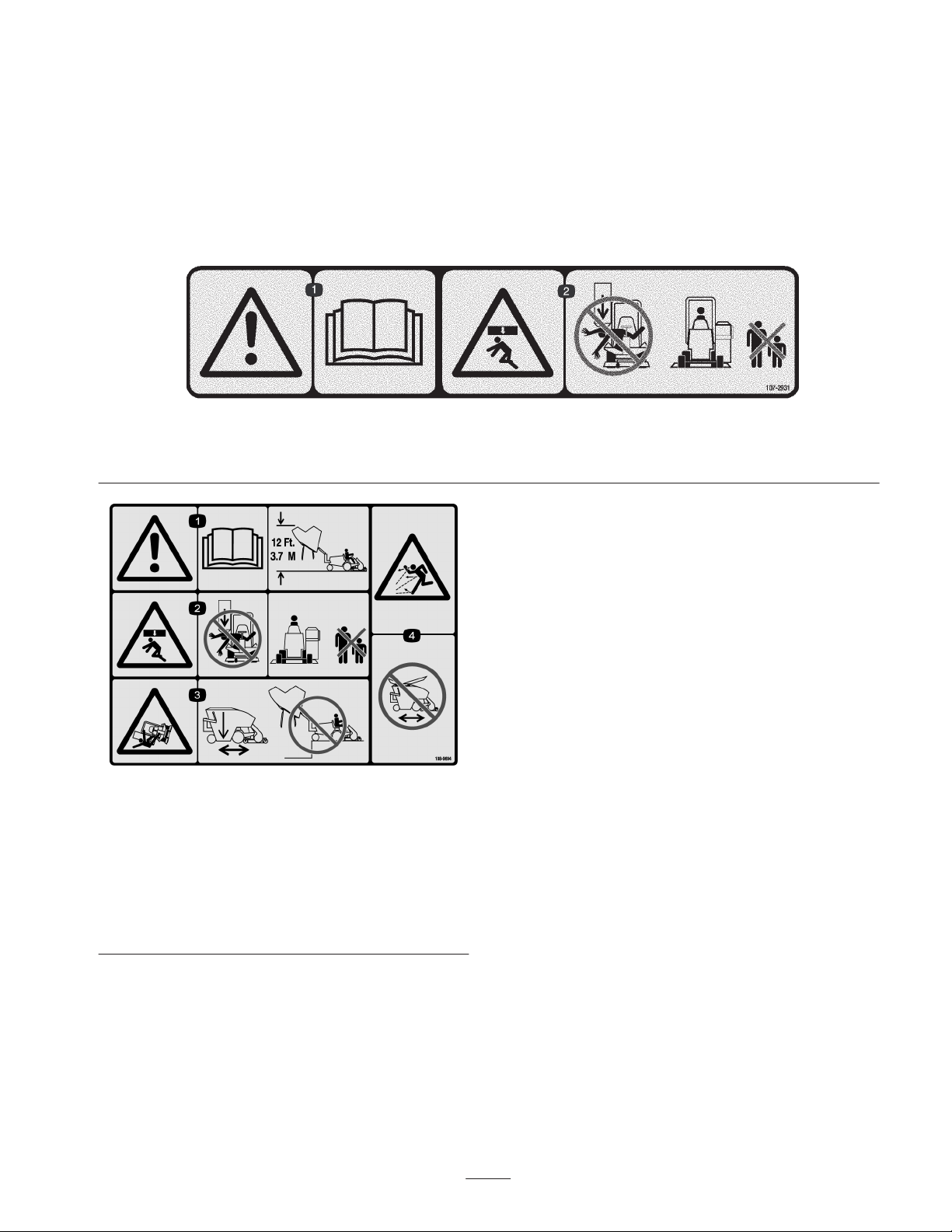
Safety and Instruction Decals
107-2931
1. Warning—read the Operator’s Manual.
2. Crushing hazard—do not get under the hopper as it lowers and keep bystanders a safe distance from the machine.
108-9694
1. Warning—read the Operator’s Manual; 12 ft (3.7 m) clearance
is required for dumping.
2. Crushing hazard—do not get under the hopper as it lowers and
keep bystanders a safe distance from the machine.
3. Tipping hazard—keep the hopper lowered while moving the
machine and do not dump the hopper over a drop-off or
embankment.
4. Thrown objects hazard—do not move the machine with the
hopper open.

4
Set Up
LOOSE PARTS CHART
Note: Use this chart as a checklist to assure all parts necessary for assembly have been received. Without these parts, total
set-up cannot be completed. Some parts may have already been assembled at factory.
Description Qty. Use
Control Valve Assembly
Control Valve Handle
Control Valve Pivot Lever
Socket Head Screw 10–24 x 1–1/4” lg.
Locknut #10–24
Clevis Pin
Cotter Pin
Hydraulic Hose
Capscrew 1/4 – 20 x 2–3/4” lg.
Flange Locknut 1/4–20
1
1
1
1
1
1
1
1
3
3
Mount Control Valve to Fender
Frame Assembly
Hopper Mounting Bracket – Left
Capscrew #10–24
Locknut #10–24
Capscrew 5/16 – 18 x 1–1/4” lg.
Locknut 5/16–18
Hopper Mounting Bracket – Right
Coupler Bracket
Capscrew 3/8 – 16 x 1” lg.
Lockwasher – 3/8
Locknut 3/8 – 16
Hopper Mounting Bracket – Rear
Strap
Capscrew 1/2 – 13 x 1–1/4” lg.
Capscrew 1/2 – 13 x 1–1/2” lg.
Flatwasher 1/2
Locknut 1/2–13
Disconnect Pin
Welded Mounting Pin – Long
Welded Mounting Pin – Short
Self Tapping Screw 1/4–20– x 3/4” lg.
1
1
4
4
4
4
1
1
4
2
2
1
2
2
2
2
4
1
1
1
2
Install Frame Assembly
Wire Harness
Cable Ties
1
6Connect Wire Harness

5
Description UseQty.
Hydraulic Hoses
Protective Sleeve
Retaining Ring
Retaining Ring
Dust Plug
Dust Cap
Quick Disconnect (nipple & coupler)
2
1
1
1
1
1
1
Connect Hydraulic Lines
Hopper Assembly
Welded Mounting Pin
Hair Pin Cotter – for 1/2” Shaft
Hair Pin Cotter – for 1/4” Shaft
Carriage Bolt 5/16 – 18 x 1” lg.
Flange Locknut 5/16–18
1
2
2
2
2
2
Install Hopper Assembly
Shield – Top
Shield – Wide
Shield – Narrow
Flat – Short
Flat – Long
Screw #10 – 24 x 1” lg.
Flange Nut #10 – 24
1
1
1
1
2
8
8
Install in Chute Opening of Hopper
Wheel Weight
Threaded Rod
Lockwasher
Flatwasher
Hex Nut
Installation Instructions
Parts Catalog
1
2
4
2
6
1
1
Mount to Left Wheel
Note: Refer to Traction Unit Operator’s Manual for left
side weight requirements.
Optional Equipment
Bracket Kit
Weight Kit
Part No. 92–9670
Part No. 24–5780

6
Mount the Control Valve
1. Remove the seat and the seat base from the machine.
2. Loosen the fuel tank mounting fasteners so the fuel tank
can be elevated enough to gain access to the right
fender.
3. Locate the (3) holes in the right fender.
•If the rear hole is located 3.74 inches from the edge
of the fender as shown in figure 1, proceed to to
step 4.
3.74
1
Figure 1
1. Right fender
•If the rear hole is located 2.74 inches from the edge
of the fender as shown in figure 2, the holes must be
relocated. Use the dimensions in figure 3 to locate,
mark and drill (3) .344 in. dia. holes in the fender.
2.74
1
Figure 2
1. Right fender 2.
2.25
3.74
3.50 1.25
.344” dia. (3)
Figure 3
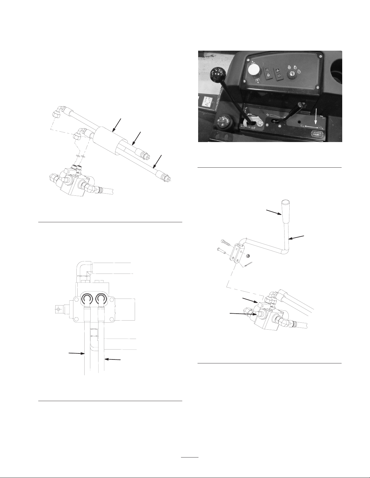
4. Mount the control valve and the pivot lever to the right
fender with (3) 1/4–20 x 2–3/4” lg. capscrews and
1/4–20 flange locknuts as shown in figure 4.
1
2
3
4
6
5
Figure 4
1. Control valve
2. Lift valve
3. Steering hose
4. Pivot lever
5. 90_fitting (operator side
of valve)
6. 90_fitting (outer side of
valve)
5. Place a drain pan under the lift valve (Fig. 4).
6. Disconnect the steering hose (Fig. 4), from the “P” port
(upper rear port) of the lift valve (hose comes from the
steering valve).
7
7. Connect the steering hose (from the lift valve “P” port)
to the 90_fitting on the operator side of the control
valve (Fig. 4).
8. Connect the hydraulic hose (included in the kit) to the
“P” port of the lift valve and to the 90_fitting on the
outer side of the control valve (Fig. 4).
9. Connect the (2) hydraulic hose assemblies to the fittings
on the top of the control valve (Fig. 5). Make sure the
O–rings are in position.
1
1
2
Figure 5
1. Hydraulic hoses 2. Protective sleeve
Note: Make sure the (2) hydraulic hoses are oriented so
they point straight out the left side of the control valve, as
shown in figure 6. This will eliminate the chance of the
hoses interfering with the fuel tank.
1
1
Figure 6
1. Hydraulic hose (2)
10. Install the protective sleeve over the hoses (Fig. 5). The
remainder of the hose installation will be completed
after the hopper frame is installed.
11. Remove the drain pan from under machine.
12. Remove the knock–out plug, under the decal, in the
lower control panel (Fig. 7).
1
Figure 7
1. Knock–out plug location
13. Mount the control valve handle to the valve spool with
a clevis pin and cotter pin. Mount the pivot lever to the
handle with a socket head screw and lock nut (Fig. 8).
2
1
3
4
Figure 8
1. Control valve handle
2. Pivot lever
3. Valve spool
4.
14. Install the control knob to the handle (Fig. 8).
15. Install the fuel tank fasteners.
16. Install the seat base and the seat.
8
Mount the Hopper Frame
Note: Remove the hairpin cotter and pin securing the right
side of the ROPS to the pivot bracket. Re–install the pin
from the left side of the pivot bracket and secure with the
hairpin cotter.
2
1
Figure 9
1. ROPS (right side) 2. Pin
1. Using the mounting holes in the left side of the frame,
secure the left hopper mounting bracket to the frame
with (4) 5/16 – 18 x 1–1/4” capscrews and locknuts
(Fig. 10). The notch in the bracket is to fit around the
hood latch.
1
Figure 10
1. Left hopper mounting
bracket
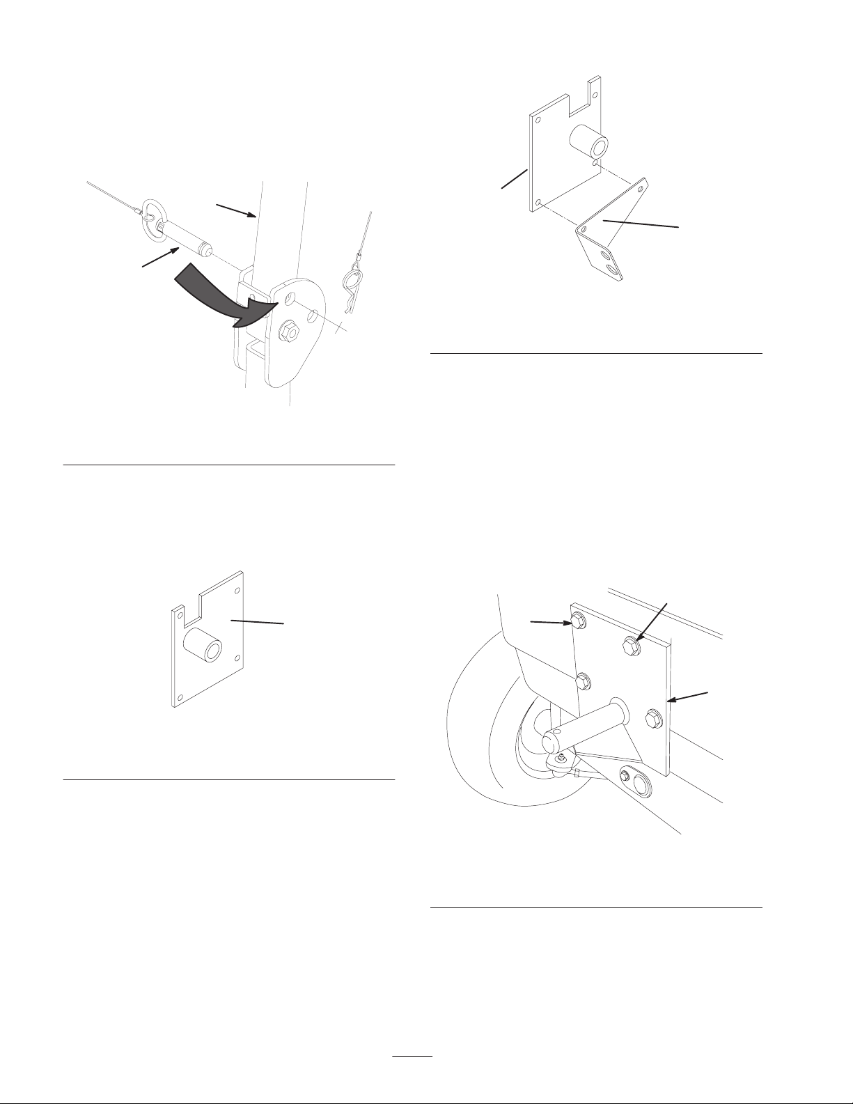
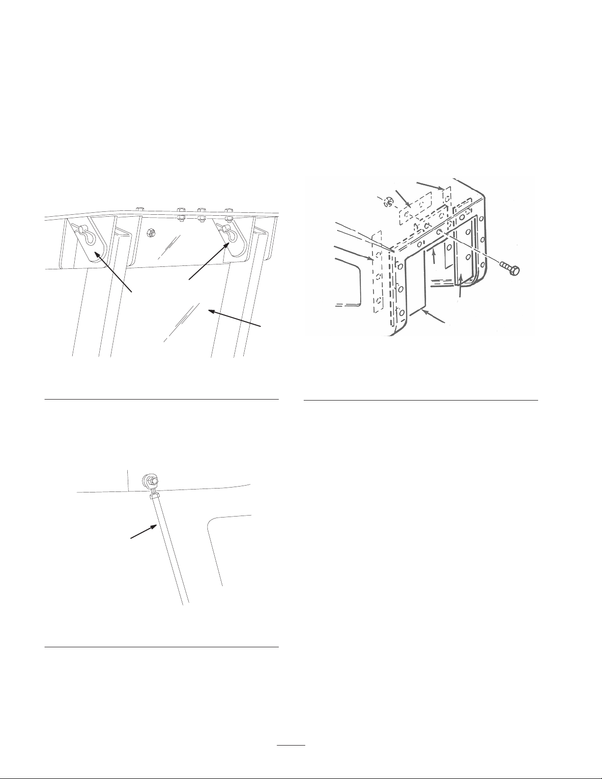
2. Secure the top of the right hopper mounting bracket to
the right side of the machine with (2) 3/8–16 x 1” lg.
capscrews and 3/8” lockwashers (Fig. 11). The notch in
the bracket is to fit around the hood latch.
1
2
Figure 11
1. Right hopper mounting
bracket
2. Coupler bracket
3. Secure the bottom of the bracket and coupler bracket to
the frame with (2) 3/8–16 x 1” lg. capscrews and
locknuts (Fig. 11).
4. Position the rear hopper bracket on the rear frame, as
shown in figure 12, while aligning the (2) bottom
mounting holes with the holes in the frame. Using the
bracket as a guide, locate, mark and drill the remaining
(2) 9/16” dia. holes in the rear frame.
5. Mount the top of the rear hopper bracket to the frame
using (2) 1/2–13 x 1–1/4” lg. capscrews, mounting strap
and (2) 1/2 – 13 locknuts (Fig. 12). The strap is to be
positioned between the frame and the bracket.
1
2
2
Figure 12
1. Rear hopper mounting
bracket
2. Drill the holes for these
capscrews
6. Mount the bottom of the bracket to the frame with (2)
1/2–13 x 1–1/2” lg. capscrews, mounting strap, 1/2
flatwashers and locknuts. The strap is to be positioned
between the frame and the bracket.
9
7. From the rear of the machine, slide the front of the
hopper frame onto the side mounting bracket pins and
the rear of the frame over the rear bracket pin.
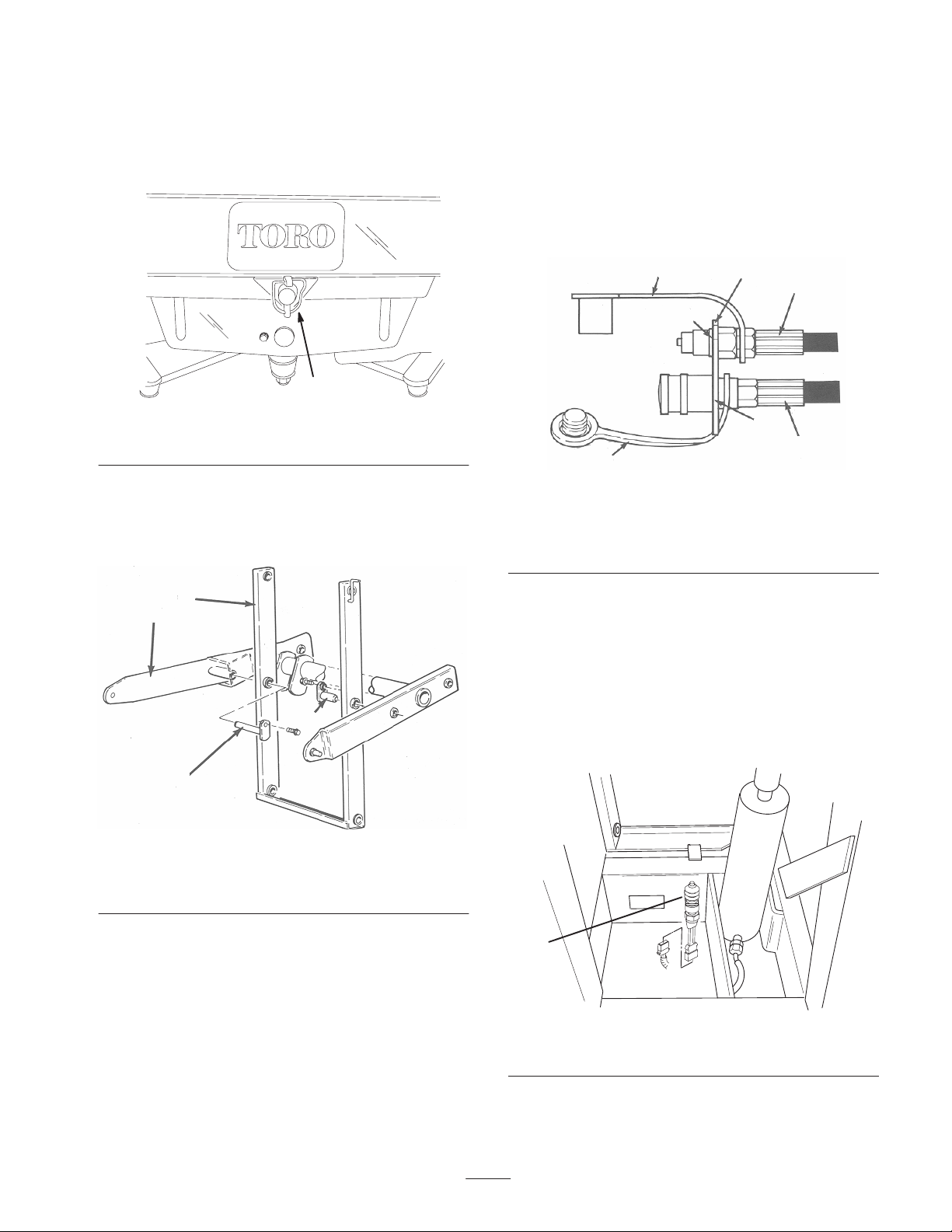
8. Secure the rear of the frame to the bracket pin with the
disconnect pin (Fig. 13).
1
Figure 13
1. Disconnect pin
9. Install the short and the long welded mounting pins
through the arm assembly and the main lift arm
assembly (Fig. 14). Secure with 1/4–20 x 3/4” lg. self
tapping screws.
2
1
3
4
Figure 14
1. Arm assembly
2. Main lift arm assembly
3. Short pin (on left side)
4. Long pin (on right side)
Connect the Hydraulic Hoses
1. Slide the loop end of the dust plug over the end of
hydraulic hose from front valve fitting. Insert the
female coupler thru the bottom hole in the coupler
bracket and secure with a retaining ring.
2. Secure the hose assembly to the female coupler
(Fig. 15).
3. Slide the loop end of the dust cap (Fig. 15) over the end
of the hydraulic hose coming from the rear valve fitting.
Install the male nipple to the hose end.
4. Insert the end of the hose thru the top hole in the
coupler bracket (Fig. 15). Secure the hose assembly to
the bracket with a retaining ring.
5. Connect the appropriate hydraulic hose from the hopper
assembly to the hoses installed to the coupler bracket.
21
3
4
6
5
3
Figure 15
1. Top hydraulic hose
2. Coupler bracket
3. Retaining ring
4. Dust cap
5. Bottom hydraulic hose
6. Dust plug
Connect the Wire Harness
1. Unplug the wire harness connector from the seat switch.
2. Plug the tee end of the hopper switch harness into the
seat switch and the seat switch harness.
3. Route the harness to the hopper switch mounted to the
frame tube (Fig. 16). Plug the harness into the switch.
1
Figure 16
1. Hopper switch
10
4. Secure the harness to stationary frame components with
cable ties.
Mount Hopper Assembly
1. Remove the tie straps securing the tie rods to the hopper
arms. Install (2) 5/16 – 18 x 1” lg. carriage bolts and
flange nuts in hopper arm holes where tie straps
previously were.
2. Slide the hopper assembly (hopper cover to rear) into
the side frame while aligning the mounting holes in
hopper with the holes in frame (Fig. 17).
2
2
1
Figure 17
1. Hopper assembly 2. Mounting pins
3. Secure the hopper to the frame with (2) welded
mounting pins and hair pin cotters (Fig. 17).
4. Secure the hopper tie rods to the frame with hair pin
cotters (Fig. 18).
1
Figure 18
1. Hopper tie rod
5. Adjust the tie rods up or down to make sure the hopper
is level with the machine and it does not contact the
machine during operation.
Install Front Blowout Shields
Note: The following instructions are as viewed from the
front of the machine.
When hopper is used with a 52” Deck
1. Secure the wide shield to the left inside lip of the
hopper opening with a long flat, (3) #10 – 24 X 1” lg.
screws and #10 – 24 flange nuts (Fig. 19).
1
2
4
52
3
Figure 19
1. Wide shield
2. Long flat
3. Narrow shield
4. Narrow shield
5. Short flat
2. Secure the narrow shield to the right inside lip of the
hopper opening with a long flat, (3) #10 – 24 X 1” lg.
screws and #10 – 24 flange nuts (Fig. 19).
3. Secure the top shield to the upper inside lip of the
hopper opening with a short flat, (2) #10 – 24 X 1” lg.
screws and #10 – 24 flange nuts (Fig. 19). Use the (2)
mounting holes on the right side of the opening only.
When hopper is used with a 60” Deck
1. Secure the wide shield to the right inside lip of the
hopper opening with a long flat, (3) #10 – 24 X 1” lg.
screws and #10 – 24 flange nuts (Fig. 20).
2. Secure the narrow shield to the left inside lip of the
hopper opening with a long flat, (3) #10 – 24 X 1” lg.
screws and #10 – 24 flange nuts (Fig. 20).
3. Cut 1–1/2” of material off the bottom edge of the top
shield. Secure the top shield to the upper inside lip of
hopper opening with a short flat, (2) #10 – 24 X 1”. lg.
screws and #10–24 flange nuts (Fig. 20). Use the (2)
mounting holes on the left side of the opening only.
11
1
2
4
5
2
6
3
Figure 20
1. Wide shield
2. Long flat
3. Narrow shield
4. Narrow shield
5. Short flat
6. Cut off 1–1/2”
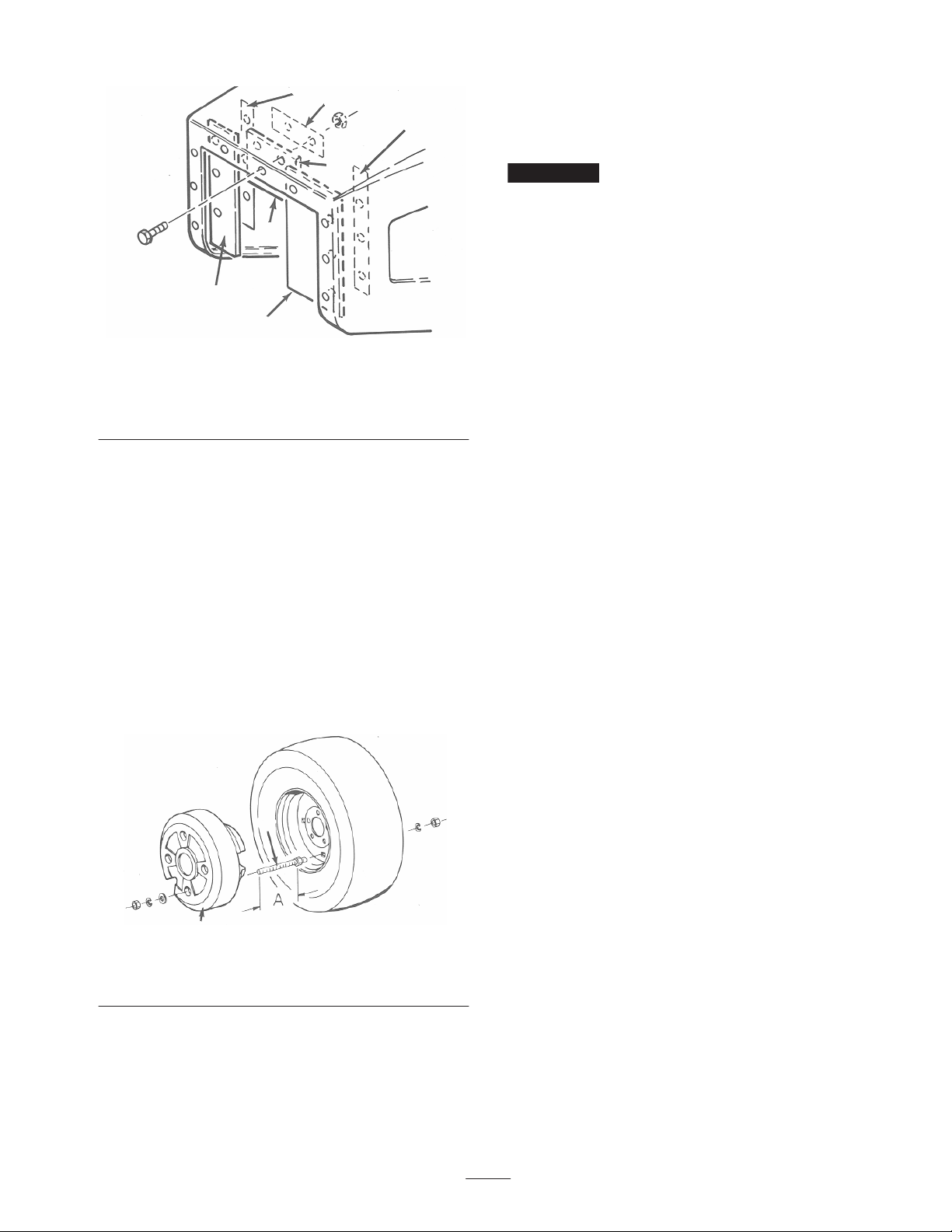
Mount Wheel Weight
1. Measure the depth of the wheel rim. This is achieved by
measuring the distance from the hole to the outside edge
of the rim.
2. Add 3–7/8” to the measurement attained. This becomes
dimension ”A” in figure 21.
3. Thread a hex nut onto each threaded rod to the ”A”
dimension.
4. Insert the threaded rods through two opposite holes in
the rim and secure them in place with 1/2” lockwashers
and hex nuts (Fig. 21).
1
2
Figure 21
1. Wheel weight 2. Threaded rod
5. Place the wheel weight over the ends of the threaded
rods and secure in place with flatwashers, lockwashers
and hex nuts (Fig. 21). Do not overtighten the hex nuts
or damage to the plastic housing of the weight may
occur.
Note: If there is excess thread protruding from the nuts or
inside of wheel, cut it off with a hacksaw. The threaded rod
must not contact any parts of the machine when the wheel
is rotating.
Important Refer to the weight chart in the Traction
Unit Operator’s Manual for additional weight requirements.

12
Operation
Note: Determine the left and right sides of the machine
from the normal operating position.
Before Operating Hopper
1. Start the engine. Raise and lower the hopper several
times. Move the control valve lever forward to lower
the hopper and in reverse direction to raise the hopper)
2. Check the interlock switch operation as follows:
•Raise the hopper and engage the PTO switch while the
engine is running. The engine should stop within 2
seconds. If the engine stops, the switch is operating
correctly; thus, proceed to next step. If the engine does
not stop, there is a malfunction in the interlock system.
•Raise the hopper and depress the traction pedal while
the engine is running and the PTO lever is disengaged.
The engine should stop within 2 seconds. If the engine
stops, the switch is operating correctly; thus, continue
operation. If the engine does not stop, there is a
malfunction in the interlock system.
3. Stop the engine. Check for hydraulic leaks. Check the
hydraulic fluid level in the front axle and replenish it as
necessary. (Refer to the Traction Unit Operator’s
Manual for specifications).
Hopper Operation
(When used with a 52” or 60” Blower Kit)
1. Move the control valve lever forward to lower the
hopper and in the reverse direction to raise the hopper.
Operating Characteristics
When the grass collector is removed, NEVER
operate without the deflector in place.
Caution
For the best performance, regulate the traction pedal to
keep engine rpm high and somewhat constant. A good rule
to follow is: decrease the ground speed as the load on the
cutting blade increases; and increase the ground speed as
the load on the blade decreases. This allows the engine,
working with the transmission, to sense the proper ground
speed while maintaining high blade tip speed necessary for
good quality–of–cut, vacuuming action, and to throw grass
into the hopper. If the blower speed drops too low, plugging
may result. Refer to the Cutting Unit and Traction Unit
Operator’s Manual for operation of each.
Use care to avoid a collision between the
hopper and any stationary objects. Always
trim with the left side of the cutting unit.
Caution
1. Inflate all the tires on the traction unit to 18–20 psi.
2. This grass collector is designed for use in wet or dry
conditions. Do not collect extremely long grass as the
hopper will fill too quickly.
3. When collecting wet, heavy grass, some clippings may
not be thrown completely through the chute. The hole in
the bottom of the chute allows these clippings to drop
out without plugging the chute. When this happens,
reduce ground speed.
Never place hands or feet in chute, blower, or
cutting unit.
Caution
4. The bumper which protects the blower housing doesn’t
extend far enough to eliminate the chance of the hopper
or hopper frame striking a stationary object. Stay far
enough away from obstructions to avoid collisions.
Trim with the left side of the cutting unit only.
5. While operating, check frequently for excessive
clippings left on the turf or uncut grass. If those
conditions occur, the blower or cutting unit may be
plugged. Stop the unit, disengage the PTO, set the brake
and shut off the ignition. Check for obstructions in the
chute, blower or cutting unit. Clear any obstruction
using a stick or similar tool. Check blower belt tension.
If slipping, readjust.
6. The grass collector hopper is designed to exhaust air
beside the chute. This allows the hopper to fill
completely without decreasing performance. Grass will
fall through the opening in the front of the hopper when
hopper is full. Immediately disengage the power take
off and empty the hopper.
7. Cut the grass often, especially when the turf growth is
rapid. If shorter turf is desired, cut the grass again.
Overlap the swaths to produce an even cutting pattern.
Important When transporting, hopper must be in down
position with rear cover latched over large cover.

13
Hopper & Frame Removal
1. Stop the unit, disengage the PTO, set the brake and shut
off the ignition.
2. Move the hopper control valve lever forward and
reverse a few times to release the pressure in the
hydraulic system.
3. Disconnect the hydraulic line quick couplers.
4. Remove the (2) hair pin cotters securing the tie rods to
the frame.
5. Remove the (2) welded mounting pins and hair pin
cotters securing the hopper to the frame. Remove the
hopper from the frame.
6. Disconnect the wire harness from the switch on the
hopper frame or seat and remove from the traction unit.
Keep harness with hopper.
Note: The hopper frame is heavy. Support the frame when
removing it or have a helper assist you.
7. Remove the disconnect pin securing the rear of the
frame to the machine. Slide the frame off the machine.
8. To prevent the contamination of the hydraulic lines,
connect the hopper lines together.
9. Insert the dust caps over the hydraulic fittings on the
machine.
14
Maintenance
Adjusting the Rear Cover Latch
1. Adjust the latch assembly (Fig. 22) up or down if the
cover does not seal properly or if the cover does not
latch when operating.
1
Figure 22
1. Latch assembly
Never work on hopper unless it is in the
lowered position.
Caution
General Practices
1. Keep the unit clean, checking that engine is free of dirt
and chaff. Make sure all fasteners are tight. Check the
deflectors, baffles and shields for wear and replace as
needed.
2. Clean grass clippings from the hopper, chute, blower
and cutting unit after each use. Wash the underside of
the cutting unit daily with a hose. An excessive buildup
of clippings will impair the collection system
performance.
3. Refer to Cutting Unit and Traction Unit Operator’s
Manuals for service requirements of each.
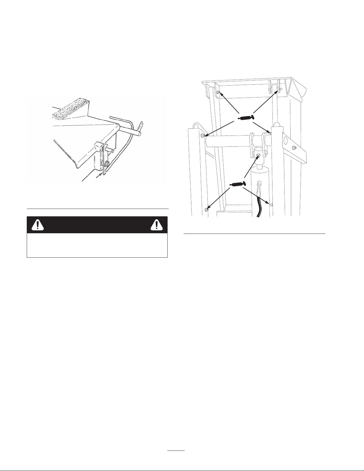
Lubrication
After every 25 hours of operation, grease the cylinder and
all pivot points with No. 2 multi–purpose lithium base
grease. There are (8) grease fittings at various pivot points
and (1) fitting on each end of cylinder (Fig. 23).
Figure 23

15

The Toro General Commercial Products Warranty
A Two-Year Limited Warranty
Conditions and Products Covered
The Toro Company and its affiliate, Toro Warranty Company,
pursuant to an agreement between them, jointly warrant your Toro
Commercial Product (“Product”) to be free from defects in
materials or workmanship for two years or 1500 operational
hours*, whichever occurs first. Where a warrantable condition
exists, we will repair the Product at no cost to you including
diagnosis, labor, parts, and transportation. This warranty begins
on the date the Product is delivered to the original retail purchaser.
* Product equipped with hour meter
Instructions for Obtaining Warranty Service
You are responsible for notifying the Commercial Products
Distributor or Authorized Commercial Products Dealer from whom
you purchased the Product as soon as you believe a warrantable
condition exists.
If you need help locating a Commercial Products Distributor or
Authorized Dealer, or if you have questions regarding your
warranty rights or responsibilities, you may contact us at:
Toro Commercial Products Service Department
Toro Warranty Company
8111 Lyndale Avenue South
Bloomington, MN 55420-1196
952-888-8801 or 800-982-2740
E-mail: [email protected]
Owner Responsibilities
As the Product owner, you are responsible for required mainte-
nance and adjustments stated in your operator’s manual. Failure
to perform required maintenance and adjustments can be grounds
for disallowing a warranty claim.
Items and Conditions Not Covered
Not all product failures or malfunctions that occur during the
warranty period are defects in materials or workmanship. This
express warranty does not cover the following:
•Product failures which result from the use of non-Toro
replacement parts, or from installation and use of add-on,
modified, or unapproved accessories
•Product failures which result from failure to perform required
maintenance and/or adjustments
•Product failures which result from operating the Product in an
abusive, negligent or reckless manner
•Parts subject to consumption through use unless found to be
defective. Examples of parts which are consumed, or used up,
during normal Product operation include, but are not limited to,
blades, reels, bedknives, tines, spark plugs, castor wheels,
tires, filters, belts, and certain sprayer components such as
diaphragms, nozzles, and check valves, etc.
•Failures caused by outside influence. Items considered to be
outside influence include, but are not limited to, weather,
storage practices, contamination, use of unapproved coolants,
lubricants, additives, or chemicals, etc.
•Normal “wear and tear” items. Normal “wear and tear” includes,
but is not limited to, damage to seats due to wear or abrasion,
worn painted surfaces, scratched decals or windows, etc.
Parts
Parts scheduled for replacement as required maintenance are
warranted for the period of time up to the scheduled replacement
time for that part.
Parts replaced under this warranty become the property of Toro.
Toro will make the final decision whether to repair any existing part
or assembly or replace it. Toro may use factory remanufactured
parts rather than new parts for some warranty repairs.
General Conditions
Repair by an Authorized Toro Distributor or Dealer is your sole
remedy under this warranty.
Neither The Toro Company nor Toro Warranty Company is
liable for indirect, incidental or consequential damages in
connection with the use of the Toro Products covered by this
warranty, including any cost or expense of providing substi-
tute equipment or service during reasonable periods of
malfunction or non-use pending completion of repairs under
this warranty. Except for the Emissions warranty referenced
below, if applicable, there is no other express warranty. All
implied warranties of merchantability and fitness for use are
limited to the duration of this express warranty.
Some states do not allow exclusions of incidental or consequential
damages, or limitations on how long an implied warranty lasts, so
the above exclusions and limitations may not apply to you.
This warranty gives you specific legal rights, and you may also
have other rights which vary from state to state.
Note regarding engine warranty: The Emissions Control System
on your Product may be covered by a separate warranty meeting
requirements established by the U.S. Environmental Protection
Agency (EPA) and/or the California Air Resources Board (CARB).
The hour limitations set forth above do not apply to the Emissions
Control System Warranty. Refer to the Engine Emission Control
Warranty Statement printed in your operator’s manual or con-
tained in the engine manufacturer’s documentation for details.
Countries Other than the United States or Canada
Customers who have purchased Toro products exported from the United States or Canada should contact their Toro Distributor (Dealer)
to obtain guarantee policies for your country, province, or state. If for any reason you are dissatisfied with your Distributor’s service or
have difficulty obtaining guarantee information, contact the Toro importer. If all other remedies fail, you may contact us at Toro Warranty
Company.
Part No. 374-0031 Rev. C
This manual suits for next models
2
Table of contents
Other Toro Industrial Equipment manuals

Toro
Toro MH-400SH2 User manual

Toro
Toro FM 330 User manual

Toro
Toro Ultra Buggy e2500 User manual

Toro
Toro 301 High Lift User manual

Toro
Toro MB TX 2500 User manual

Toro
Toro MH-400SH2 User manual

Toro
Toro LAC TM User manual

Toro
Toro TX 1300 User manual

Toro
Toro Workman 07224-90001 Instruction Manual

Toro
Toro 22340 User manual


