2--7 Settings
Features Settings
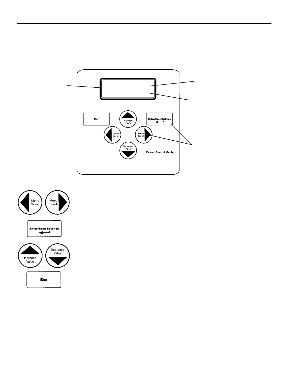
The controller (CP) Features settings can be displayed and changed from the key-
pad. Some settings may require a password (if the controller is set up for one).
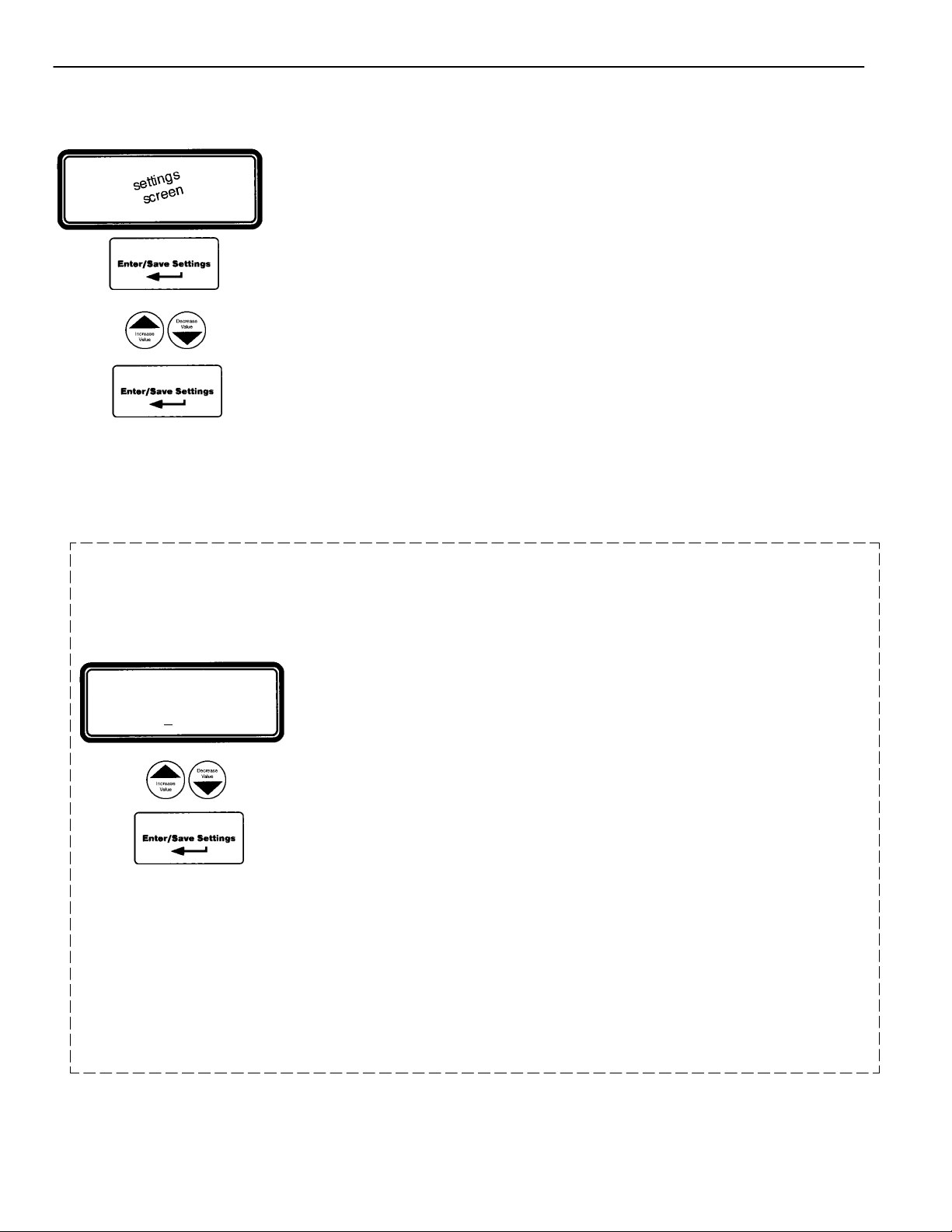
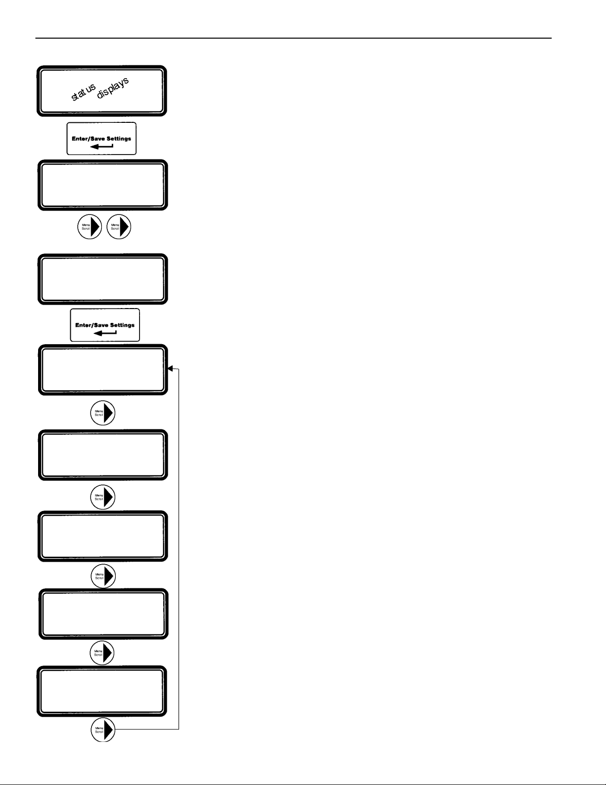
¡From any of the Status displays, press the Enter/Save Settings ¿key to move
to the Settings level of menus.
©Then press the right arrow "key to move to Setting Time Delays menu.
¢Press the right arrow "key again to move to Settings Features menu.
£Now press Enter/Save Settings ¿keytomovetothefirstFeatures display
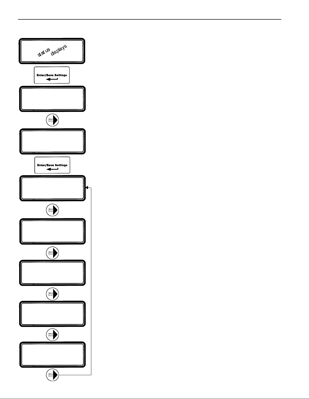
¤You can press the right arrow "key to see the other Features menus (as shown
below). An overview explanation of each setting is listed below.
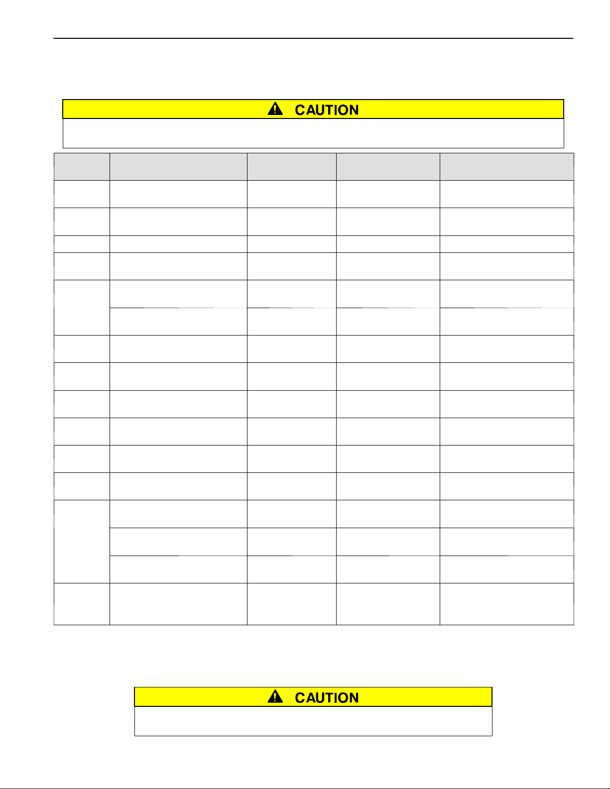
7 Features Menus (last menu loops back to first)
Commit to Xfer After TD Normal Fail seepage2–1
This display shows the commit to transfer setting. It affects the transfer
sequence as follows:
Ye s — If Normal fails, CP continues transfer sequence to emergency
even if Normal returns before Emergency becomes acceptable.
No — If Normal fails, CP cancels the transfer sequence to emergency
if Normal returns before Emergency becomes acceptable.
Shed Load seepage2–1
This display shows status of 3 load shed parameters:
Direction —from Emergency or from Normal
InPhase —yes means transfer delayed until sources are in phase
TD — 3 second default time delay
Shed Load Options seepage2–1
This display appears only for 4ACTS, 4ADTS, 7ACTS, 7ACTB, 7ADTS, or
7ADTB. It determines switch position after the shed load transfer.
IsoLoadOnSrcFail — determines switch position during a source failure.
IsoLoadOnTest17 — deterines switch position during feature 17 activation.
Ye s — Load is not connected to either source. (see wiringdiagram
No — Load is connected to the opposite source. for feature 17 desc.)
Phase Rotation Monitor seepage2–1
This display shows status of phase rotation monitor and desired reference
phase rotation. It only appears if both sources are set to 3–phase sensing.
Enabled —Ye s means phase rotation is considered as part of the
source acceptability criteria for each source. If the phase rotation of the
source does not match the reference phase rotation, that source is considered
unacceptable. If phase rotation of the two sources is different, the load will
be transferred to the source with the reference phase rotation.
Reference — phase rotation order: ABC or CBA (ABC is default)
In–Phase Monitor seepage2–1
This display appears only for 4ATS, 7ATS or 7ATB. This display shows status
of in–phase monitor and in–phase time delay (1.5 seconds is default setting).
Enabled —Ye s means in–phase transfer is initiated when any of these
conditions are met: Transfer Test (Feature 5) signal, connected source fails,
retransfer to acceptable Normal occurs and Emergency source acceptable.
CTTS Bypass / Shed Load (not shown)see page 2–1
This display shows status of the closed–transition bypass options.
FailSyncAutoBypass —Ye s means if the fail to sync alarm occurs, the controller
will bypass the closed–transition mode and will make a delayed–transiton
transfer. The load disconnect time is set by the Bypass DT Delay parameter.
Bypass InPhase —Ye s means the inphase monitor is active during load transfer.
SETTINGS
Voltage DO PU
Frequency DO PU
¡
©¢
Commit to Xfer After
TD Normal Fail: _
SHED LOAD
Direction:
InPhase: TD: s
PHASE ROTATION
MONITOR
Enable:
Reference:
£
SETTINGS
Features
¤
IN--PHASE
MONITOR
Enable:
Time Delay: s
SHED LOAD
IsoLoadOnSrcFail yes
IsoLoadOnTest17 no