aion TRITON MK. III User manual

TRITON PREAMP DRIVE MK. III 1
PROJECT NAME
TRITON MK. III
BASED ON
EFFECT TYPE
PROJECT SUMMARY
DOCUMENT VERSION
Catalinbread®Dirty Little Secret V3
An adaptation of the classic Marshall®amplifiers from the 1960s. It uses cascaded mu-amp stages in
place of tubes for amp-like tone in a small box.
Overdrive / Amp Emulation 1.0.1 (2021-02-19)
Actual size is 2.3” x 1.86” (main board) and 1.78” x 0.87” (bypass board).
BUILD DIFFICULTY
Intermediate
This documentation is for the Mk. III version of the project. There is also a Mk. II version, based on
the Dirty Little Secret Mk. II. While the name is similar, the circuit and part numbering are different.
Please be sure your PCB is labeled “Triton Mk. III” before proceeding with this build document.
IMPORTANT NOTE

TRITON PREAMP DRIVE MK. III 2
TABLE OF CONTENTS
1Project Overview 7Drill Template
2Introduction & Usage 8Enclosure Layout
3-4 Parts List 9Wiring Diagram
5Build Notes 10 Licensing
6Schematic 10 Document Revisions
INTRODUCTION
The Triton Preamp Drive Mk. III is an adaptation of the Catalinbread Dirty Little Secret Mk. III, their
“amp in a box” voiced with a Marshall amplifier in mind. This third version was released in early 2013.
The Formula 5F6, released a few months later in the summer of 2013, is the same circuit with several
tweaks in part values to make it more like Fender’s tweed Bassman amplifier from the late 1950s (which
was Jim Marshall’s source for the first Marshall amps). With the Triton PCB, you can build either the
DLS or 5F6, as well as the hotter “Red” special edition of the DLS from 2019.
The production version of the DLS includes an internal slide switch to go between “Super Lead” and
“Super Bass” modes. This slide switch has four poles, with two poles controlling the gain and two poles
controlling the tone stack. The Triton splits this into two discrete toggle switches so you can switch the
gain and tone stacks independently, e.g. the gain of the Super Bass but the tonestack of the Super Lead.
Like several other Catalinbread pedals, this circuit blurs the line between a preamp and an overdrive.
Like a true preamplifier, it’s very reactive to what comes before it, so it’s best placed after other drive
pedals but before modulation. However, it also generates more than enough drive on its own and can be
used as a standalone overdrive pedal just like any other.
The original DLS Mk. III used MPF4393 JFETs, which are no longer produced. Aion FX sells the original
MPF4393 in sets of 5. The PCB also has an extra pad so that surface-mount JFETs can be used (part
number MMBF4393), which are still in production and perform identically to those used in Catalinbread
pedals. See build notes for more details.
The Triton Mk. III is compatible with the 18V Voltage Doubler / Bypass module if you want to run the
circuit at 18V without an external adapter. The higher voltage provides increased volume and clarity.
USAGE
The Triton Mk. III has the following controls:
• Preamp controls the amount of gain in the first amplifier stage.
• Bass, Middle and Treble form a 3-band Fender/Marshall-style tone stack.
• Master is the overall output level.
• Presence (internal trimmer) is a treble-cut control at the end of the circuit.
• Gain (toggle switch) selects between Super Lead and Super Bass gain stages.
• Tone (toggle switch) selects between Super Lead and Super Bass tone stack capacitor values.

TRITON PREAMP DRIVE MK. III 3
PARTS LIST
This parts list is also available in a spreadsheet format which can be imported directly into Mouser for
easy parts ordering. Mouser doesn’t carry all the parts (most notably potentiometers) so the second tab
lists all the non-Mouser parts as well as sources for each.
View parts list spreadsheet →
PART VALUE TYPE NOTES
R1 470k Metal film resistor, 1/4W Formula 5F6: 680k
R2 33k Metal film resistor, 1/4W
R3 1M Metal film resistor, 1/4W Formula 5F6: 470k
R4 1k Metal film resistor, 1/4W Carbon comp in original, measured value 711R
R5 1k Metal film resistor, 1/4W DLS Red: 270R
R6 1M Metal film resistor, 1/4W
R7 1M Metal film resistor, 1/4W
R8 47k Metal film resistor, 1/4W
R9 470k Metal film resistor, 1/4W
R10 470k Metal film resistor, 1/4W
R11 680R Metal film resistor, 1/4W Carbon comp in original, measured value 560R
Formula 5F6: 1k8
DLS Red: 1k
R12 1k Metal film resistor, 1/4W DLS Red: 270R
R13 1M Metal film resistor, 1/4W
R14 1M Metal film resistor, 1/4W
R15 100k Metal film resistor, 1/4W Formula 5F6: 33k
DLS Red: 91k
R16 56k Metal film resistor, 1/4W
R17 33k Metal film resistor, 1/4W Formula 5F6: 100k
R18 1k Metal film resistor, 1/4W
R19 2M2 Metal film resistor, 1/4W
R20 2M2 Metal film resistor, 1/4W
R21 4k7 Metal film resistor, 1/4W
R22 100R Metal film resistor, 1/4W
LEDR 4k7 Metal film resistor, 1/4W LED current-limiting resistor. Adjust value to change LED brightness.
C1 220n Film capacitor, 7.2 x 2.5mm
C2 1n Film capacitor, 7.2 x 2.5mm
C3 2n2 Film capacitor, 7.2 x 2.5mm Formula 5F6: 4n7
DLS Red: 100n
C4 2.2uF Film capacitor, 7.2 x 5mm Formula 5F6: 1uF
Can also substitute electrolytic (polarity marked on PCB)
C5 22uF Electrolytic capacitor, 5mm DLS Red: 27uF
C6 680n Film capacitor, 7.2 x 4.5mm Formula 5F6: omit (C7 is used instead)
DLS Red: 1uF

TRITON PREAMP DRIVE MK. III 4
PARTS LIST, CONT.
PART VALUE TYPE NOTES
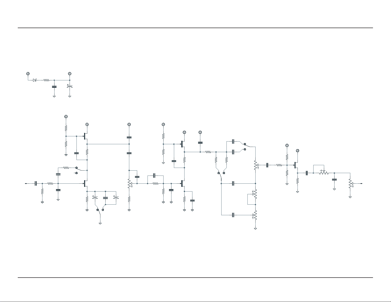
C7 (omit) Formula 5F6: 4.7uF electrolytic
C8 220pF MLCC capacitor, NP0/C0G
C9 22n Film capacitor, 7.2 x 2.5mm
C10 47pF MLCC capacitor, NP0/C0G Formula 5F6: 100pF
C11 470pF MLCC capacitor, NP0/C0G Formula 5F6: (omit)
C12 470pF MLCC capacitor, NP0/C0G Formula 5F6: (omit)
C13 2.2uF Film capacitor, 7.2 x 5mm Formula 5F6: 1uF
Can also substitute electrolytic (polarity marked on PCB)
C14 680n Film capacitor, 7.2 x 4.5mm Formula 5F6: 1uF
DLS Red: 1uF
C15 470pF MLCC capacitor, NP0/C0G Formula 5F6: 220pF
C16 270pF MLCC capacitor, NP0/C0G Formula 5F6: 220pF
C17 470pF MLCC capacitor, NP0/C0G
C18 22n Film capacitor, 7.2 x 2.5mm
C19 22n Film capacitor, 7.2 x 2.5mm
C20 22n Film capacitor, 7.2 x 2.5mm
C21 220n Film capacitor, 7.2 x 2.5mm
C22 10n Film capacitor, 7.2 x 2.5mm
C23 100uF Electrolytic capacitor, 6.3mm Power supply filter capacitor.
C24 100n MLCC capacitor, X7R Power supply filter capacitor.
D1 1N5817 Schottky diode, DO-41
Q1 MMBF4393 JFET, N-channel, SOT-23 Substitute for MPF4393 (TO-92). See build notes.
Q2 MMBF4393 JFET, N-channel, SOT-23 Substitute for MPF4393 (TO-92). See build notes.
Q3 MMBF4393 JFET, N-channel, SOT-23 Substitute for MPF4393 (TO-92). See build notes.
Q4 MMBF4393 JFET, N-channel, SOT-23 Substitute for MPF4393 (TO-92). See build notes.
Q5 MMBF4393 JFET, N-channel, SOT-23 Substitute for MPF4393 (TO-92). See build notes.
PRE. 1MA 16mm right-angle PCB mount pot
TREBLE 250kB 16mm right-angle PCB mount pot
MID 25kB 16mm right-angle PCB mount pot
BASS 1MA 16mm right-angle PCB mount pot
MAST. 250kB 16mm right-angle PCB mount pot
PRES. 10k trimmer Trimmer, 10%, 1/4”
GAIN DPDT on-on Toggle switch, DPDT on-on
TONE DPDT on-on Toggle switch, DPDT on-on
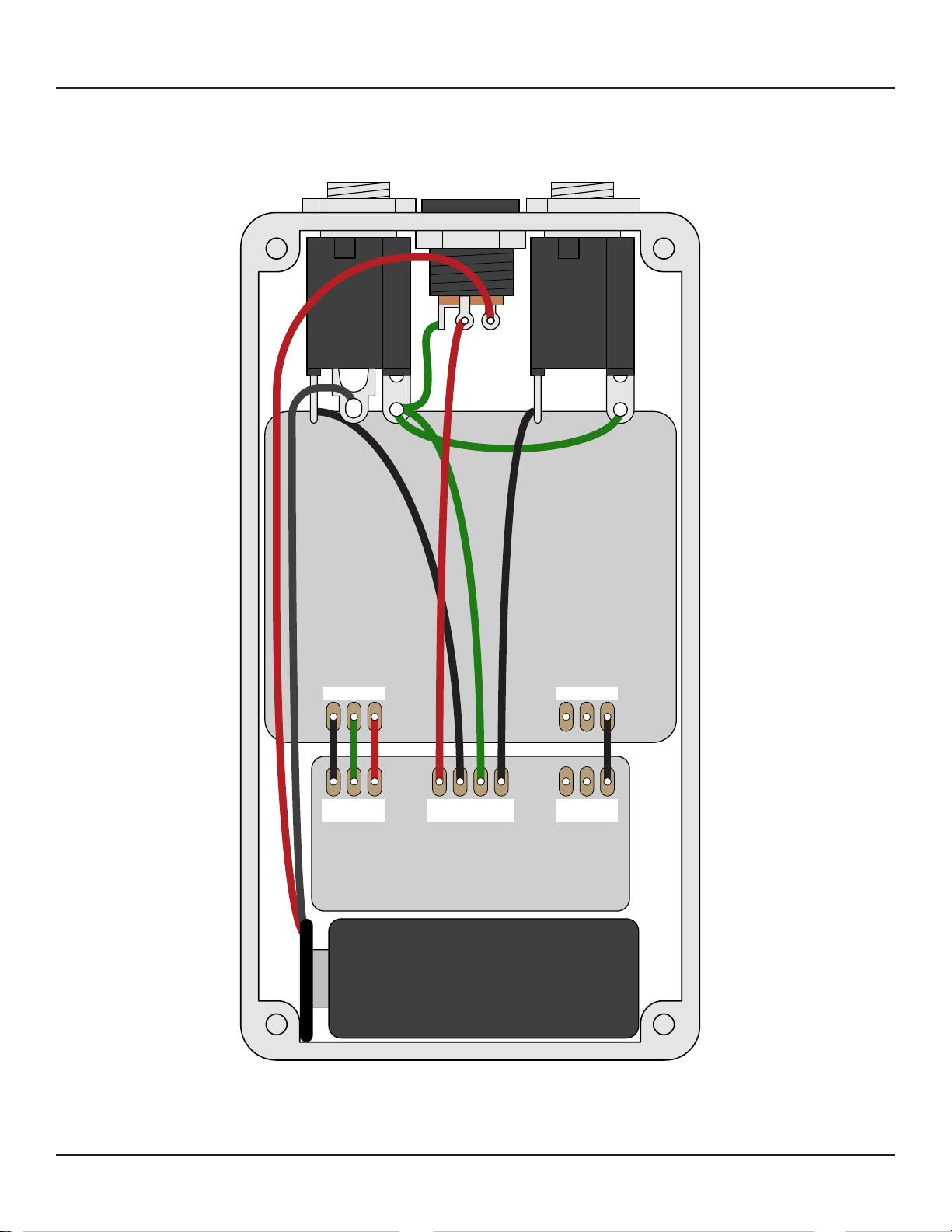
IN 1/4" stereo 1/4" phone jack, closed frame Switchcraft 112BX or equivalent.
OUT 1/4" mono 1/4" phone jack, closed frame Switchcraft 111X or equivalent.
DC 2.1mm DC jack, 2.1mm panel mount Mouser 163-4302-E or equivalent.
FSW 3PDT Stomp switch, 3PDT
ENC 125B Enclosure, die-cast aluminum Can also use a Hammond 1590N1.

TRITON PREAMP DRIVE MK. III 5
BUILD NOTES
Using SMD JFETs
The MPF4393 JFET is no longer available from the original manufacturer in through-hole format.
This PCB uses a hybrid through-hole/SMD outline for each JFET. An extra “G” (gate) pad is included to
accommodate the MMBF4393 surface-mount version without the need for adapters.
SMD JFETs should be oriented as follows:
All surface-mount JFETs use the same pinout, so this configuration will fit any type that we’re aware
of. However, always check the datasheet if you’re uncertain—they’re difficult to desolder if you make a
mistake.
MPF4393s from Aion FX
We have a large quantity of through-hole MPF4393 and should be able to provide them in hobbyist
quantities for the foreseeable future. They are available in sets of 5. They are manufactured by ON
Semiconductor, the same as those used in the original Catalinbread pedal. They test in the same range
and will perform identically.

SCHEMATIC
TRITON PREAMP DRIVE MK. III 6
GND
470k
5817
100uF
1MA
GND
250kB
+9V
100n
VA
220n
33k
1M
MPF4393
2n2
2u2
1k
MPF4393
1k
1M 1M
VA
VA
GND
GND
22n
47pF
GND
470k MPF4393
680R
GND
MPF4393
1k
2u2
1M 1M
VA
GND
VA
GND
100R
47k
GND
22uF 680n
220pF
VA
470pF
470k
470pF
GND GND 680n
GND
100k
470pF
VA
56k
33k
470pF 270pF22n22n
25kB 1MA
250kB
GND
22n
1k
2M22M2
MPF4393
VA
GND
4k7
GND
1n
GND
220n
10kB
10n
VA
GND
OMIT
IN OUT
R1
D1
C23
PREAMP
1
2
3
MASTER
1
2
3
C24
C1
R2
R3
Q1
C3
C4
R5
Q2
R4
R6 R7
C9
C10
R9 Q3
R11
Q4
R12
C13
R13 R14
R22
R8
C5 C6
C8
C11
R10
C12
C14
R15
C15
R16
R17
C17 C16C18C19
1
2
3
MIDDLE
1
2
3
BASS
TREBLE
1
2
3
C20
R18
R19R20
Q5
R21
C2
C21
1
2
3
PRESENCE C22
C7
TONE A
A2
A3
A1
TONE B
B2
B3
B1
GAIN A
A2
A3
A1
GAIN B
B2
B3
B1
GND
Schematic shown with original Dirty Little Secret Mk. III values.
Alternate values for DLS Red and Formula 5F6 can be found in the parts list.

TRITON PREAMP DRIVE MK. III 7
DRILL TEMPLATE
Cut out this drill template, fold the edges and tape it to the enclosure. Before drilling, it’s recommended
to first use a center punch for each of the holes to help guide the drill bit.
Ensure that this template is printed at 100% or “Actual Size”. You can double-check this by measuring
the scale on the printed page.
Top jack layout assumes the use of closed-frame jacks like the Switchcraft 111X. Open-frame jacks will
not fit in layouts with 5 or more knobs due to the placement of the DC jack.
LED hole drill size assumes the use of a 5mm LED bezel, available from several parts suppliers. Adjust
size accordingly if using something different, such as a 3mm bezel, a plastic bezel, or just a plain LED.
0 1 2
CM
0 1
INCH
x: -0.775, y: +1.71 x: +0.775, y: +1.71
ø9/32” ø9/32”
x: -0.775, y: +0.41
ø9/32”
x: 0, y: +1.71
ø9/32”
x: +0.775, y: +0.41
ø9/32”
x: 0, y: -1.20
ø15/32”
x: -0.775, y: -1.20
ø5/16”
CENTER (0,0)
125B
BASSMIDDLE
TONE
GAIN
TONE
GAIN
TREBLE
PREAMPMASTER
FOOTSWITCHLED
ø3/8” ø1/2”
0.385”
0.625” 0.625”
ø3/8”
OUT DC IN
x: 0, y: +0.16
ø1/4”
x: 0, y: +0.66
ø1/4”

TRITON PREAMP DRIVE MK. III 8
ENCLOSURE LAYOUT
Enclosure is shown without jacks. See next page for jack layout and wiring.
125B

TRITON PREAMP DRIVE MK. III 9
WIRING DIAGRAM
125B
IN +VGND N.C. N.C. OUT
PCB
IN
GND +V +V JACK GND JACK
OUTIN
GND GND PCB
OUT

TRITON PREAMP DRIVE MK. III 10
LICENSE & USAGE
No direct support is offered for these projects beyond the provided documentation. It’s assumed
that you have at least some experience building pedals before starting one of these. Replacements and
refunds cannot be offered unless it can be shown that the circuit or documentation are in error.
All of these circuits have been tested in good faith in their base configurations. However, not all the
modifications or variations have necessarily been tested. These are offered only as suggestions based
on the experience and opinions of others.
Projects may be used for commercial endeavors in any quantity unless specifically noted. No
attribution is necessary, though a link back is always greatly appreciated. The only usage restrictions
are that (1) you cannot resell the PCB as part of a kit without prior arrangement, and (2) you cannot
“goop” the circuit, scratch off the screenprint, or otherwise obfuscate the circuit to disguise its source.
(In other words: you don’t have to go out of your way to advertise the fact that you use these PCBs, but
please don’t go out of your way to hide it. The guitar effects industry needs more transparency, not less!)
DOCUMENT REVISIONS
1.0.1 (2021-02-19)
Corrected note about open-frame jacks (these are not compatible with 5-knob pedals).
1.0.0 (2020-11-27)
Initial release.
Table of contents
Other aion Music Pedal manuals

aion
aion Minima User manual

aion
aion theseus User manual

aion
aion PHOBOS User manual

aion
aion ASTRA SILICON FUZZ User manual

aion
aion Lab Series User manual

aion
aion PROCYON User manual

aion
aion IBEX User manual

aion
aion BUSINESS CARD DRIVE User manual

aion
aion Cadmus User manual

aion
aion Gladiator Dual Drive User manual