ASTRA SILICON FUZZ 3
PARTS LIST
This parts list is also available in a spreadsheet format which can be imported directly into Mouser for
easy parts ordering. Mouser doesn’t carry all the parts (most notably potentiometers) so the second tab
lists all the non-Mouser parts as well as sources for each.
View parts list spreadsheet →
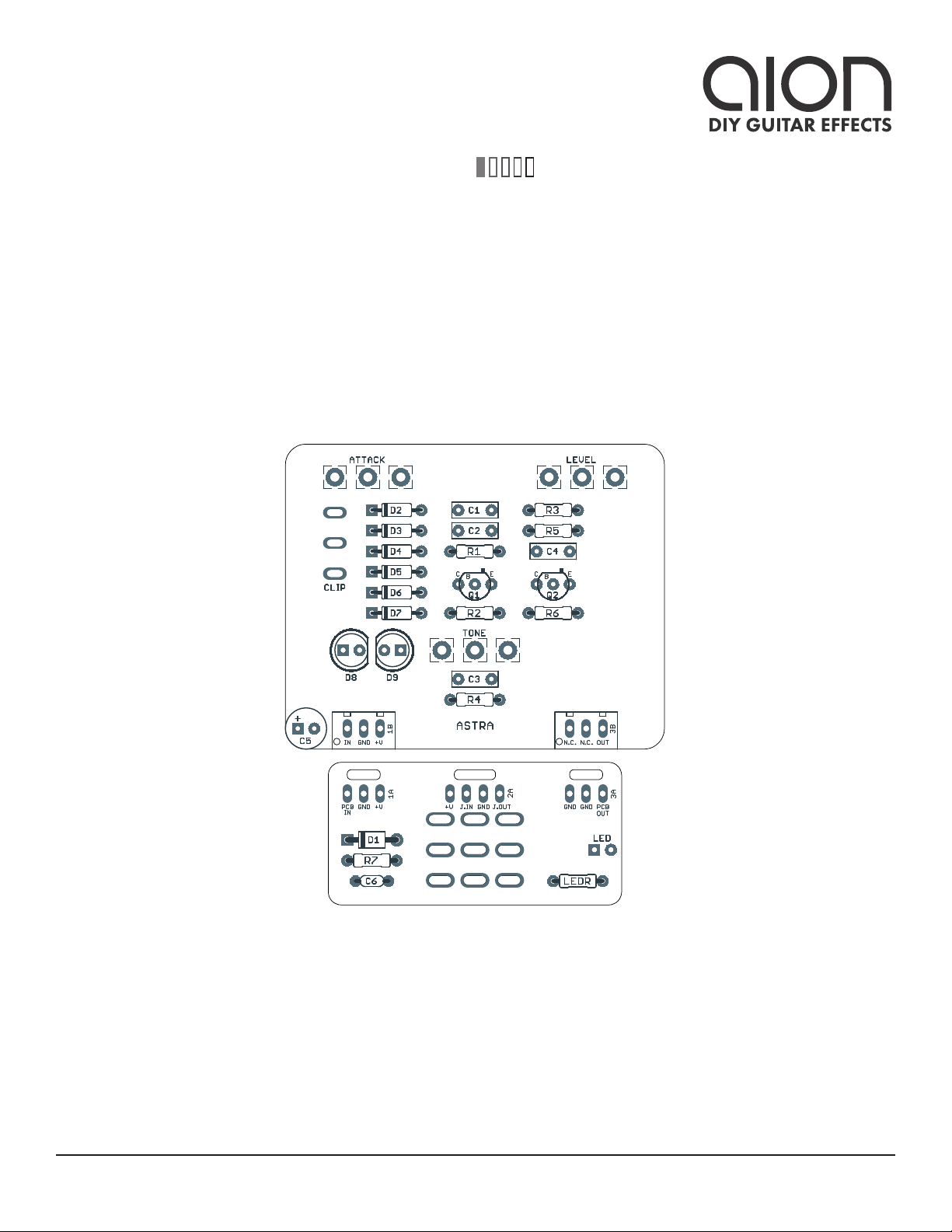
PART VALUE TYPE NOTES
R1 1M Metal film resistor, 1/4W Analogman version uses 1.2M here.
R2 22k Metal film resistor, 1/4W
R3 470k Metal film resistor, 1/4W
R4 1M Metal film resistor, 1/4W Analogman version uses 1.2M here.
R5 1k8 Metal film resistor, 1/4W
R6 1k8 Metal film resistor, 1/4W Analogman version uses 470R here.
R7 100R Metal film resistor, 1/4W Power supply filter resistor (not on original unit)
LEDR 4k7 Metal film resistor, 1/4W LED current-limiting resistor. Adjust value to change LED brightness.
C1 47n Film capacitor, 7.2 x 2.5mm Analogman version uses 470n here.
C2 47n Film capacitor, 7.2 x 2.5mm
C3 47n Film capacitor, 7.2 x 2.5mm
C4 47n Film capacitor, 7.2 x 2.5mm Analogman version uses 470n here.
C5 100uF Electrolytic capacitor, 6.3mm Power supply filter capacitor.
C6 100n MLCC capacitor, X7R Power supply filter capacitor.
D1 1N5817 Schottky diode, DO-41
D2 1N914 Fast-switching diode, DO-35
D3 1N914 Fast-switching diode, DO-35
D4 1N914 Fast-switching diode, DO-35
D5 1N914 Fast-switching diode, DO-35
D6 1N914 Fast-switching diode, DO-35
D7 1N914 Fast-switching diode, DO-35
D8 5mm LED, 5mm, red diffused Can also use 3mm LEDs.
D9 5mm LED, 5mm, red diffused Can also use 3mm LEDs.
Q1 2N3904 BJT transistor, NPN, TO-92 Original uses 2N3565. 2N3904 is an exact substitute.
Q2 2N3904 BJT transistor, NPN, TO-92 Original uses 2N3565. 2N3904 is an exact substitute.