aion NYSIAD Silicon Fuzz User manual

NYSIAD SILICON FUZZ 1
PROJECT NAME
NYSIAD
BASED ON
EFFECT TYPE
PROJECT SUMMARY
DOCUMENT VERSION
Cornish NG-3
A variable-bias silicon fuzz designed to emulate “imminent amp death”, the sound of a blown power tube
or output transformer right before it all goes up in smoke.
Misbiased silicon fuzz 2.0.0 (2023-10-06)
Actual size is 2.3” x 2.43” (main board) and 2.3” x 0.87” (bypass board).
BUILD DIFFICULTY
Intermediate

NYSIAD SILICON FUZZ 2
TABLE OF CONTENTS
1Project Overview 9Drill Template
2Introduction 10 Enclosure Layout
2-3 Usage 11 Wiring Diagram
4-6 Parts List 12 Licensing
7Build Notes 12 Document Revisions
8Schematic
INTRODUCTION
The Nysiad Silicon Fuzz is adapted from the Cornish NG-3, first released in 2010 as the successor to
the NG-2 and N.G. Fuzz, both favorites of Lou Reed who owned several of each, and also used by John
Mayer on his version of Crossroads. Aion FX traced the NG-3 in 2023.
The NG-3 is designed to simulate “imminent amp death”, the sound of a bad output transformer or
power tube right before the fuse blows (or worse). You can get some fairly traditional sounds from it if
the bias knob is all the way up, but once you start to dial it down, the tone quickly turns into a glitchy
mess, complete with gating, sag, feedback, velcro, instability, and anything else you’d associate with a
misbiased fuzz.
The closest comparison is probably the ZVEX Fuzz Factory. They’re different animals, but if you like the
sounds you can get from that circuit then you’ll probably like this one too.
According to Pete, the NG-3 is the same as the NG-2 except that the internal bias control has been made
into an external knob. In truth, it’s not quite that simple, though probably mostly accurate. Our tracing
journal includes extensive analysis and speculation on this question if you’re curious.
The Nysiad is a direct clone of the original Cornish pedal based on our trace, with the one addition that
buffered bypass can be changed to true bypass with a slide switch, as on our other Cornish adaptations.
USAGE
The Nysiad has the following controls:
• Drive is the amount of clean boost from the op-amp gain stage at the beginning. As it’s boosted, it
overloads the first transistor stage, creating the initial fuzz tone.
• Sustain controls the signal level coming out of the first transistor gain stage, which affects how
much the second transistor gain stage is overloaded, adding to the fuzz tone.
• Bias sets the bias of the second transistor stage, which sets how much of the signal is amplified. At
full clockwise, the bias is normal and full signal is passed. As it’s turned down, gating effects and
“velcro” artifacts start to appear.
• Tone is a basic bass/treble filter identical to the type found in a Big Muff.
• Volume is the overall output.
(continued on next page)

NYSIAD SILICON FUZZ 3
USAGE, CONT.
Overview
The NG-3 is great at what it does, but it’s very important to understand what exactly that is. The circuit
is intended to sound like it’s broken, but it’s been designed to get these broken sounds in reliable and
repeatable ways. This means it can be difficult to tell whether it’s been built successfully, especially if
you’ve never played one before.
The two best things you can do to understand the circuit are 1) watch a demo video such as this one
from Shnobel Tone, and 2) study the schematic to see exactly how the circuit is arranged, particularly
what each control is supposed to do, since the control labels are not overly intuitive.
Beyond that, we’re including a few notes from our own experience to help you get the most out of it.
Bias control
When you first complete the Nysiad build, the bias control should be turned all the way up (clockwise).
This provides the most “normal” fuzz tone. Drive, Sustain and Tone should be around 12:00.
As you turn down the bias control, the circuit becomes more and more unstable and glitchy, especially at
higher Drive and Sustain settings.
Drive vs. Sustain
These controls seem redundant at first glance, but think of them as inter-stage gain controls. Drive is the
signal level going into transistor stage 1, and Sustain is the signal level going into transistor stage 2. The
first transistor stage overloads differently than the second, so high Drive and low Sustain sounds very
different than low Drive and high Sustain.
Generally speaking, the Sustain control has a stronger interaction with the Bias control. For example,
with Bias at 12:00 and Sustain toward the bottom half of the rotation, there’s a very strong “sag” effect,
almost like an over-eager compressor that reduces the gain too much before swelling back to normal.
The Drive level has much less of an impact on this effect.
Noise
The noise floor will be amplified a great deal at higher Drive and Sustain levels, so if you have single-coil
pickups, you’ll have better luck with one of the noise-canceling positions. This is less of an issue as Bias is
turned down since there’s a noise-gating effect when nothing is being played.

NYSIAD SILICON FUZZ 4
PARTS LIST
This parts list is also available in a spreadsheet format which can be imported directly into Mouser for
easy parts ordering. Mouser doesn’t carry all the parts (most notably potentiometers) so the second tab
lists all the non-Mouser parts as well as sources for each.
View parts list spreadsheet →
PART VALUE TYPE NOTES
R1 10M Metal film resistor, 1/4W
R2 1k Metal film resistor, 1/4W
R3 120k Metal film resistor, 1/4W
R4 120k Metal film resistor, 1/4W
R5 200k Metal film resistor, 1/4W
R6 7k5 Metal film resistor, 1/4W
R7 10k Metal film resistor, 1/4W
R8 51R Metal film resistor, 1/4W
R9 100k Metal film resistor, 1/4W
R10 1M Metal film resistor, 1/4W
R11 1M Metal film resistor, 1/4W
R12 3k3 Metal film resistor, 1/4W
R13 10k Metal film resistor, 1/4W
R14 1k5 Metal film resistor, 1/4W
R15 150k Metal film resistor, 1/4W
R16 33k Metal film resistor, 1/4W
R17 1k Metal film resistor, 1/4W
R18 4k3 Metal film resistor, 1/4W
R19 30k Metal film resistor, 1/4W
R20 82R Metal film resistor, 1/4W
R21 220k Metal film resistor, 1/4W
R22 10k Metal film resistor, 1/4W
R23 68k Metal film resistor, 1/4W
R24 30k Metal film resistor, 1/4W
R25 12k Metal film resistor, 1/4W
R26 28k Metal film resistor, 1/4W
R27 28k Metal film resistor, 1/4W
R28 330k Metal film resistor, 1/4W
R29 100k Metal film resistor, 1/4W
R30 120k Metal film resistor, 1/4W
R31 120k Metal film resistor, 1/4W
R32 200k Metal film resistor, 1/4W

NYSIAD SILICON FUZZ 5
PARTS LIST, CONT.
PART VALUE TYPE NOTES
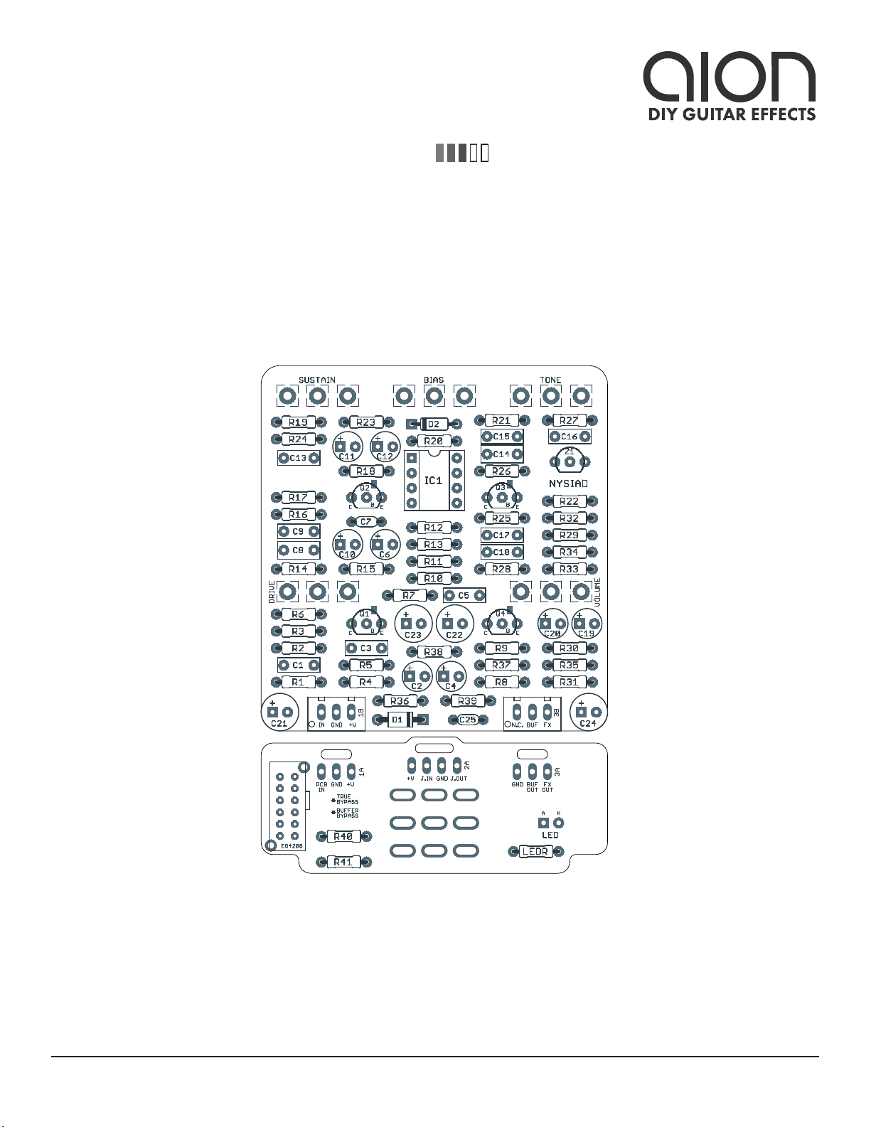
R33 5k1 Metal film resistor, 1/4W
R34 10k Metal film resistor, 1/4W
R35 91R Metal film resistor, 1/4W
R36 100R Metal film resistor, 1/4W
R37 150R Metal film resistor, 1/4W
R38 150R Metal film resistor, 1/4W
R39 150R Metal film resistor, 1/4W
R40 91R Metal film resistor, 1/4W
R41 51k Metal film resistor, 1/4W
LEDR 10k Metal film resistor, 1/4W LED current-limiting resistor. Adjust value to change LED brightness.
C1 100n Film capacitor, 7.2 x 2.5mm
C2 4.7uF Electrolytic capacitor, 4mm
C3 1n Film capacitor, 7.2 x 2.5mm
C4 22uF Electrolytic capacitor, 5mm
C5 100n Film capacitor, 7.2 x 2.5mm
C6 4.7uF Electrolytic capacitor, 4mm
C7 100pF MLCC capacitor, NP0/C0G
C8 220n Film capacitor, 7.2 x 2.5mm
C9 1n Film capacitor, 7.2 x 2.5mm
C10 22uF Electrolytic capacitor, 5mm
C11 4.7uF Electrolytic capacitor, 4mm
C12 4.7uF Electrolytic capacitor, 4mm
C13 1n Film capacitor, 7.2 x 2.5mm
C14 220n Film capacitor, 7.2 x 2.5mm
C15 10n Film capacitor, 7.2 x 2.5mm
C16 10n Film capacitor, 7.2 x 2.5mm
C17 100n Film capacitor, 7.2 x 2.5mm
C18 1n Film capacitor, 7.2 x 2.5mm
C19 4.7uF Electrolytic capacitor, 4mm
C20 22uF Electrolytic capacitor, 5mm
C21 220uF Electrolytic capacitor, 6.3mm Power supply filter capacitor.
C22 220uF Electrolytic capacitor, 6.3mm Power supply filter capacitor.
C23 220uF Electrolytic capacitor, 6.3mm Power supply filter capacitor.
C24 220uF Electrolytic capacitor, 6.3mm Power supply filter capacitor.
C25 100n MLCC capacitor, X7R Power supply filter capacitor.
D1 1N5817 Schottky diode, DO-41
D2 1N914 Fast-switching diode, DO-35

NYSIAD SILICON FUZZ 6
PARTS LIST, CONT.
PART VALUE TYPE NOTES
Q1 BC549C BJT transistor, NPN, TO-92
Q2 BC549C BJT transistor, NPN, TO-92
Q3 BC549C BJT transistor, NPN, TO-92
Q4 BC549C BJT transistor, NPN, TO-92
Z1 LM4040DIZ-5.0 Zener / voltage reference, TO-92 Can also use LM4040CIZ-5.0.
IC1 TL071 BJT transistor, NPN, TO-92
IC1-S DIP-8 socket BJT transistor, NPN, TO-92
DRIVE 100kA 16mm right-angle PCB mount pot
SUSTAIN 100kB 16mm right-angle PCB mount pot
TONE 100kB 16mm right-angle PCB mount pot
BIAS 100kB 16mm right-angle PCB mount pot
VOLUME 250kA 16mm right-angle PCB mount pot
TB-BUF 4PDT slide Slide switch, 4PDT E-Switch EG4208 (4mm lever) or EG4208A (6mm lever)
IN 1/4" mono 1/4" phone jack, closed frame Switchcraft 111X or equivalent.
OUT 1/4" mono 1/4" phone jack, closed frame Switchcraft 111X or equivalent.
DC 2.1mm DC jack, 2.1mm panel mount Mouser 163-4302-E or equivalent.
FSW 3PDT Stomp switch, 3PDT
ENC 125B Enclosure, die-cast aluminum Can also use a Hammond 1590N1.

NYSIAD SILICON FUZZ 7
BUILD NOTES
Bypassing the true bypass / buffer switch
The E-Switch EG4208 slide switch used for the true bypass/buffer selector is available from Mouser
Electronics but may not be accessible to everyone. If you are unable to obtain it, you can hard-wire the
switch to either true bypass mode or buffered mode by soldering jumpers to the switch pads.
Transistor substitutions
The BC549C and BC550C are interchangeable with no difference in sound, so either can be used. If you
want to substitute a different transistor, you’ll want one with very high hFE, in the 600s.
The PCB layout uses the B-C-E transistor pinout, which is the opposite of the E-B-C convention used by
transistors with a “2N” prefix such as the 2N3904. The closest substitute in this series is the 2N5089. If
using these, rotate them 180 degrees. Use a multimeter to check the pinout if you’re not sure.
The transistor outlines also include a rectangular collector pad above the “B” and “E” pins so that a SMD
transistor such as the BC849C can be used.
Z1 zener/reference voltage
Z1 (LM4040DIZ-5.0) is a micropower zener diode in a TO-92 transistor package, intended for high-
precision voltage references at low operating currents. Accordingly, the bias resistors (R21-23 and the
Bias pot) are a lot larger than you’d expect.
These micropower types are designed to be extremely stable at low currents and they do not need a
filter capacitor according to the datasheet. If Z1 was a standard zener diode, it would likely not drop its
full 5V voltage and would be noisy or unstable without a filter capacitor.
The LM4040 is the only part that will work properly without circuit modifications. The tolerance grade
suffix (A = 0.1%, B = 0.2%, C = 0.5%, or D = 1%) is unimportant, so you can substitute whichever type is
easiest to find as long as it’s 5.0V. The traced NG-3 used the LM4040DIZ-5.0, which is the cheapest type,
but the CIZ has been used in the Cornish OC-1.
BUFFER BYPASS
TRUE BYPASS

NYSIAD SILICON FUZZ 8
SCHEMATIC
TO PCB IN
BUFFER OUT
TO INPUT JACK
TO OUTPUT JACK
FROM BUFFER OUT
FROM EFFECT OUT
SWITCH POSITIONS SHOWN
Slide switch: TBP mode
Footswitch: bypass mode
OUT
IN
LM4040
DIZ-5.0
1N5817
+9V
100n
100R
220uF
GND
91R
51k
10M
100n
1k
120k
1n
4.7uF
BC549C
7k5
22uF
10k
51R
GND GND
GND
100k
GND
GND
120k200k
GND
VA
150R
100n
10k
VD
1M1M3k3
GND
4.7uF
TL071CP
100pF
GND
220uF
VA
VA
GND
VC
150R
220uF
GND
150R
220uF
GND
VE
VD
VD
100kA
220n
1k5
150k33k
VC
GND
1n
BC549C
1k 4k3
VC
GND
22uF
GND
4.7uF
100kB
30k
GND
4.7uF
82R
1N914 220k
10k
68k
GND
100kB
GND
VE
GND
30k
GND
1n
BC549C
12k
VE
GND
220n
28k
10n
28k
100kB
10n
GND GND
250kA
GND
330k
100k
100n
GND
120k
1n
4.7uF
BC549C
5k1
22uF
10k
91R
GND GND
120k200k
GND
VE
VE
GND
GND
D1
A2
A3
A1 FSA
C2
C3
C1 FSC
3
C25
R36
C21
SW1A
2
3
1
SW1B
5
6
4
SW1C
8
9
7
SW1D
11
12
10
R40
R41
R1
C1
R2
R3
C3
C2
Q1
R6
C4
R7
R8
R9
R4R5
R37
C5
R13
R10R11R12
C6
5
1
2
3
6
8
74
IC1
C7
C22
R38
C23
R39
C24
1
2
3
DRIVE
C8 R14
R15R16
C9
Q2
R17 R18
C10
C11
SUSTAIN
1
2
3
R19
C12
R20
D2 R21
R22
R23
BIAS
1
2
3
Z1
R24
C13
Q3
R25
C14 R26
C15
R27
TONE
1
2
3
C16
VOLUME
1
2
3
R28
R29
C17
R30
C18
C19
Q4
R33
C20
R34
R35
R31R32

NYSIAD SILICON FUZZ 9
DRILL TEMPLATE
Cut out this drill template, fold the edges and tape it to the enclosure. Before drilling, it’s recommended
to first use a center punch for each of the holes to help guide the drill bit.
Ensure that this template is printed at 100% or “Actual Size”. You can double-check this by measuring
the scale on the printed page.
Top jack layout assumes the use of closed-frame jacks like the Switchcraft 111X. Open-frame jacks will
not fit in layouts with 5 or more knobs due to the placement of the DC jack.
LED hole drill size assumes the use of a 5mm LED bezel, available from several parts suppliers. Adjust
size accordingly if using something different, such as a 3mm bezel, a plastic bezel, or just a plain LED.
0 1 2
CM
0 1
INCH
ø3/8” ø1/2”
0.385”
0.625” 0.625”
x: -0.775, y: +1.71 x: +0.775, y: +1.71
ø9/32” ø9/32”
x: +0.775, y: +0.41
ø9/32”
x: 0, y: -1.775
ø15/32”
x: -0.775, y: -1.775
ø5/16”
CENTER (0,0)
ø3/8”
125B
OUT
TONE
x: -0.775, y: +1.71
ø9/32”
BIAS SUSTAIN
x: -0.775, y: +0.41
ø9/32”
VOLUME DRIVE
FOOTSWITCHLED
DC IN

NYSIAD SILICON FUZZ 10
ENCLOSURE LAYOUT
Enclosure is shown without jacks. See next page for jack layout and wiring.
125B

NYSIAD SILICON FUZZ 11
WIRING DIAGRAM
125B
IN +VGND NC BUF FX
PCB
IN
GND +V +V JACK GND JACK
OUTIN
GND BUF
OUT
FX
OUT

NYSIAD SILICON FUZZ 12
LICENSE & USAGE
No direct support is offered for these projects beyond the provided documentation. It’s assumed
that you have at least some experience building pedals before starting one of these. Replacements and
refunds cannot be offered unless it can be shown that the circuit or documentation are in error.
All of these circuits have been tested in good faith in their base configurations. However, not all the
modifications or variations have necessarily been tested. These are offered only as suggestions based
on the experience and opinions of others.
Projects may be used for commercial endeavors in any quantity unless specifically noted. No
attribution is necessary, though a link back is always greatly appreciated. The only usage restrictions
are that (1) you cannot resell the PCB as part of a kit without prior arrangement, and (2) you cannot
“goop” the circuit, scratch off the screenprint, or otherwise obfuscate the circuit to disguise its source.
(In other words: you don’t have to go out of your way to advertise the fact that you use these PCBs, but
please don’t go out of your way to hide it. The guitar effects industry needs more transparency, not less!)
DOCUMENT REVISIONS
2.0.0 (2023-10-06)
New PCB layout to add P-2 compatibility based on our trace. Changed transistor outlines to BC549/550
convention. Changed R7 to 10k and added information on this change to the build notes section.
1.0.2 (2023-08-04)
Changed R39 to 51k and added information on this change to the build notes section.
1.0.1 (2020-04-06)
Added notes about resistors in first transistor stage (R18 and R19).
1.0.0 (2019-03-14)
Initial release.
Table of contents
Other aion Music Pedal manuals

aion
aion ASTRA SILICON FUZZ User manual

aion
aion Nimbus User manual

aion
aion HORIZON User manual

aion
aion ZIRCON SILICON FUZZ User manual

aion
aion TRITON MK. III User manual

aion
aion UBE SCREAMER User manual

aion
aion TEMPEST User manual

aion
aion CONSTELLATION User manual

aion
aion REFRACTOR User manual

aion
aion FRACTAL PARAMETRIC OVERDRIVE User manual