ANDROMEDA NATURAL OVERDRIVE 4
PARTS LIST, CONT.
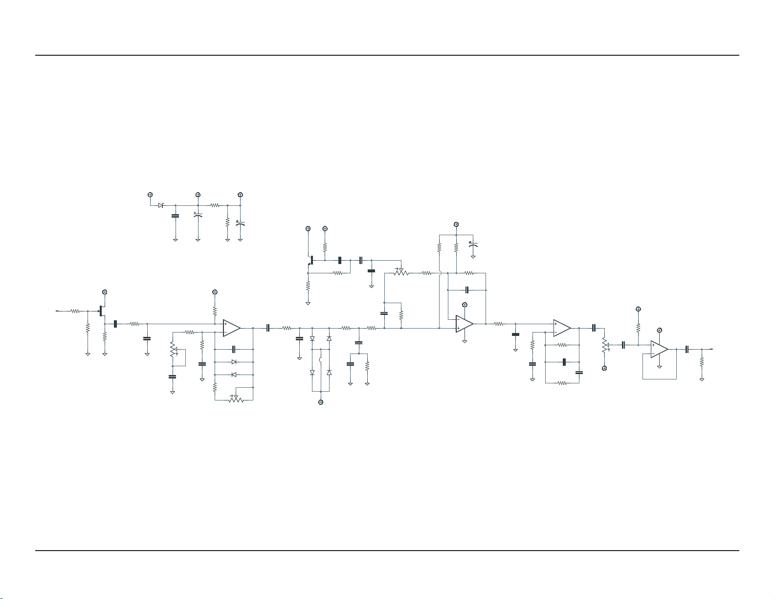
PART VALUE TYPE NOTES
C1 68n Film capacitor, 7.2 x 2.5mm
C2 22n Film capacitor, 7.2 x 2.5mm
C3 120pF MLCC capacitor, NP0/C0G
C4 82n Film capacitor, 7.2 x 2.5mm
C5 2.2uF Film capacitor, 7.2 x 5mm
C6 2.2uF Film capacitor, 7.2 x 5mm
C7 2n7 Film capacitor, 7.2 x 2.5mm
C8 82n Film capacitor, 7.2 x 2.5mm
C9 1n Film capacitor, 7.2 x 2.5mm
C10 22n Film capacitor, 7.2 x 2.5mm
C11 27n Film capacitor, 7.2 x 2.5mm
C12 100n Film capacitor, 7.2 x 2.5mm
C13 8n2 Film capacitor, 7.2 x 2.5mm
C14 560pF MLCC capacitor, NP0/C0G
C15 8n2 Film capacitor, 7.2 x 2.5mm
C16 4n7 Film capacitor, 7.2 x 2.5mm
C17 82n Film capacitor, 7.2 x 2.5mm
C18 1uF Film capacitor, 7.2 x 3.5mm
C19 2.2uF Film capacitor, 7.2 x 5mm
C20 470n Film capacitor, 7.2 x 3.5mm
C21 1uF Film capacitor, 7.2 x 3.5mm
C22 100uF Electrolytic capacitor, 6.3mm Power supply filter capacitor.
C23 47uF Electrolytic capacitor, 5mm Reference voltage filter capacitor.
C24 47uF Electrolytic capacitor, 5mm Reference voltage filter capacitor.
C25 100n MLCC capacitor, X7R Power supply filter capacitor.
D1 1N5817 Schottky diode, DO-41
D2 1N914 Fast-switching diode, DO-35
D3 1N914 Fast-switching diode, DO-35
D4 1N914 Fast-switching diode, DO-35
D5 1N914 Fast-switching diode, DO-35
D6 1N914 Fast-switching diode, DO-35 Optional. Bridge the jumper pads between D6 and D7 for the stock
ODR-1 circuit.
D7 1N914 Fast-switching diode, DO-35 Optional. Bridge the jumper pads between D6 and D7 for the stock
ODR-1 circuit.