aion HALO User manual

HALO DISTORTION / SUSTAINER 1
PROJECT NAME
HALO
BASED ON
EFFECT TYPE
PROJECT SUMMARY
DOCUMENT VERSION
Electro-Harmonix Big Muff Pi
One of the most classic guitar effects of all time, its sound falls somewhere between a distortion effect
and a fuzz with an incredibly long sustain.
Fuzz / Distortion 2.0.0 (2019-12-14)
Actual size is 2.3” x 1.86” (main board) and 1.78” x 0.87” (bypass board).
BUILD DIFFICULTY
Easy

HALO DISTORTION / SUSTAINER 2
TABLE OF CONTENTS
1Project Overview 8Drill Template
2Introduction & Usage 9Enclosure Layout
3-4 Parts List 10 Wiring Diagram
5-6 Build Notes 11 Licensing
7Schematic 11 Document Revisions
INTRODUCTION
The Halo Distortion/Sustainer is a recreation of the Electro-Harmonix Big Muff Pi, first released in
1969. Originally marketed as a “harmonic distortion sustain”, it has been lumped together with fuzz
effects, although it’s a very different animal than classic fuzz effects like a Fuzz Face or a Tone Bender.
While the overall circuit has barely changed in 50+ years, Electro-Harmonix was legendary for changing
the part values on a whim throughout that time while never advertising the new versions as being
different than previous ones. There are around 20 notable variants and many more minor variations
within those, with nearly every part in the circuit being tweaked at some point or another.
The Big Muff is a pretty easy build and there aren’t a lot of things that can be messed up. There’s no
biasing or gain sorting for the transistors, and no rare or specialized parts. It’s endlessly tweakable,
with dozens of different variants that can be replicated by substituting a few parts. For this reason,
it’s become a very popular DIY build—something of a rite of passage for those getting into the hobby.
It’s also a great way to experiment and learn how simple audio circuits work, because almost any part
substitution will have some sort of audible effect.
The Halo is a faithful recreation of the Big Muff, allowing any standard variant to be built. A versions
spreadsheet compiles all the different variants so you can easily see which parts to substitute if you
want to build a Triangle, Ram’s Head, Civil War, or more than a dozen other flavors.
Also included is a midrange switch that allows for the stock mid-scoop tone, a flat midrange response, or
boosted midrange. The presence control mod from the legacy version of the Halo has been removed in
this version, but the legacy PCB is still available for those who want it.
USAGE
The Halo has the following controls:
• Sustain controls the amount of drive or distortion, which also affects the amount of sustain.
• Tone is a control that pans between a low-pass filter (high cut) and a high-pass filter (low cut). At the
12:00 position, the bass and treble are flat, and the midrange tone response is based on the setting
of the Mids switch.
• Volume is the overall output.
• Mids allows you to switch between Mid Scoop (the stock setting), Mid Hump, or Flat Mids.

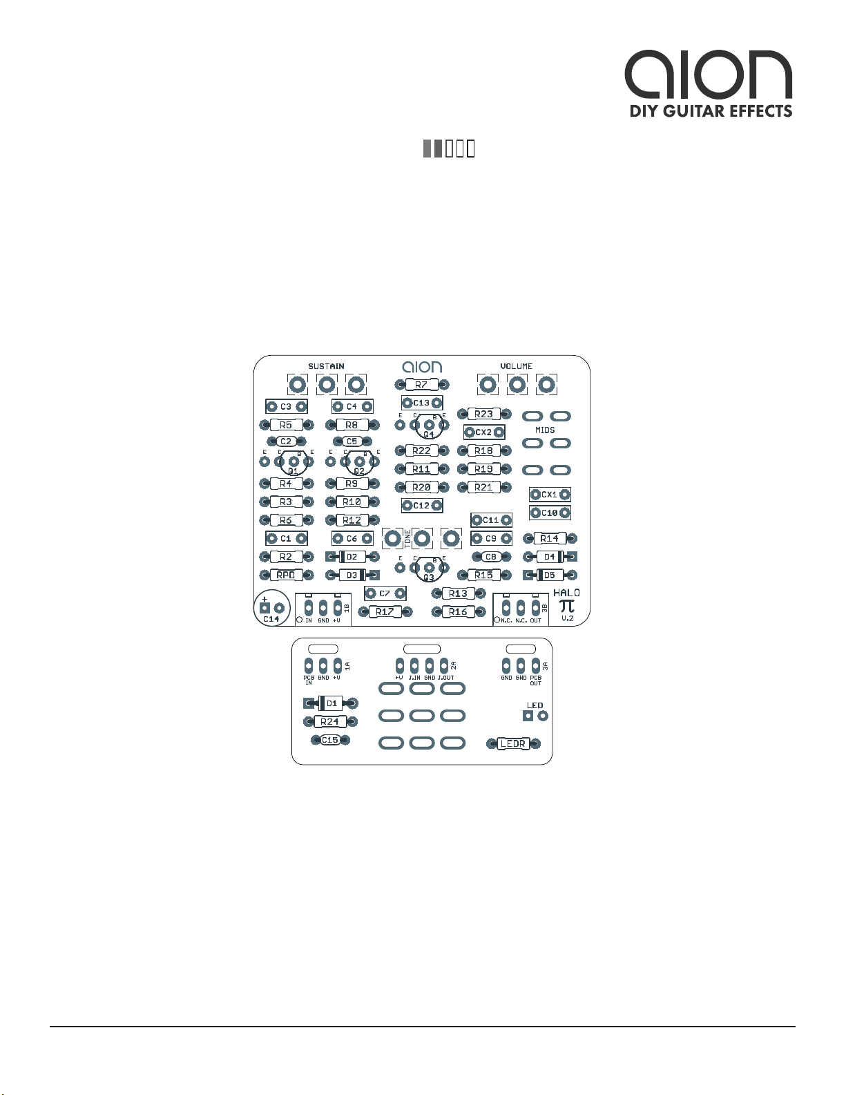
HALO DISTORTION / SUSTAINER 3
PARTS LIST
This parts list is also available in a spreadsheet format which can be imported directly into Mouser for
easy parts ordering. Mouser doesn’t carry all the parts (most notably potentiometers) so the second tab
lists all the non-Mouser parts as well as sources for each.
View parts list spreadsheet →
Note: The parts list is taken from the “Gilmour ‘73 Ram’s Head” version. See the Big Muff Versions
spreadsheet for a compilation of all major versions of the Big Muff with part number references.
PART VALUE TYPE NOTES
R2 33k Metal film resistor, 1/4W
R3 100k Metal film resistor, 1/4W
R4 470k Metal film resistor, 1/4W
R5 100R Metal film resistor, 1/4W
R6 10k Metal film resistor, 1/4W
R7 560R Metal film resistor, 1/4W
R8 10k Metal film resistor, 1/4W
R9 100k Metal film resistor, 1/4W
R10 470k Metal film resistor, 1/4W
R11 100R Metal film resistor, 1/4W
R12 10k Metal film resistor, 1/4W
R13 10k Metal film resistor, 1/4W
R14 100k Metal film resistor, 1/4W
R15 470k Metal film resistor, 1/4W
R16 100R Metal film resistor, 1/4W
R17 10k Metal film resistor, 1/4W
R18 33k Metal film resistor, 1/4W
R19 33k Metal film resistor, 1/4W
R20 470k Metal film resistor, 1/4W
R21 100k Metal film resistor, 1/4W
R22 10k Metal film resistor, 1/4W
R23 2k7 Metal film resistor, 1/4W
R24 100R Metal film resistor, 1/4W Power supply filter resistor.
RPD 2M2 Metal film resistor, 1/4W Input pulldown resistor. Can be as low as 1M.
LEDR 4k7 Metal film resistor, 1/4W LED current-limiting resistor. Adjust value to change LED brightness.
C1 100n Film capacitor, 7.2 x 2.5mm
C2 470pF MLCC capacitor, NP0/C0G
C3 100n Film capacitor, 7.2 x 2.5mm
C4 100n Film capacitor, 7.2 x 2.5mm

HALO DISTORTION / SUSTAINER 4
PARTS LIST, CONT.
PART VALUE TYPE NOTES
C5 470pF MLCC capacitor, NP0/C0G
C6 100n Film capacitor, 7.2 x 2.5mm
C7 100n Film capacitor, 7.2 x 2.5mm
C8 470pF MLCC capacitor, NP0/C0G
C9 100n Film capacitor, 7.2 x 2.5mm
C10 3n9 Film capacitor, 7.2 x 2.5mm
C11 12n Film capacitor, 7.2 x 2.5mm
C12 100n Film capacitor, 7.2 x 2.5mm
C13 100n Film capacitor, 7.2 x 2.5mm
C14 100uF Electrolytic capacitor, 6.3mm Power supply filter capacitor.
C15 100n MLCC capacitor, X7R Power supply filter capacitor.
CX1 12n Film capacitor, 7.2 x 2.5mm For other variants, this value should always be the same as C11.
CX2 3n9 Film capacitor, 7.2 x 2.5mm For other variants, this value should always be the same as C10.
Q1 2N3904 BJT transistor, NPN, TO-92 Can also use 2N5088.
Q2 2N3904 BJT transistor, NPN, TO-92 Can also use 2N5088.
Q3 2N3904 BJT transistor, NPN, TO-92 Can also use 2N5088.
Q4 2N3904 BJT transistor, NPN, TO-92 Can also use 2N5088.
D1 1N5817 Schottky diode, DO-41
D2 1N914 Fast-switching diode, DO-35
D3 1N914 Fast-switching diode, DO-35
D4 1N914 Fast-switching diode, DO-35
D5 1N914 Fast-switching diode, DO-35
TONE 100kB 16mm right-angle PCB mount pot
SUST. 100kB 16mm right-angle PCB mount pot
VOL. 100kA 16mm right-angle PCB mount pot
MIDS DPDT on-on-on Toggle switch, DPDT on-on-on
IN 1/4" stereo 1/4" phone jack, closed frame Switchcraft 112BX or equivalent.
OUT 1/4" mono 1/4" phone jack, closed frame Switchcraft 111X or equivalent.
DC 2.1mm DC jack, 2.1mm panel mount Mouser 163-4302-E or equivalent.
FSW 3PDT Stomp switch, 3PDT
ENC 125B Enclosure, die-cast aluminum Can also use a Hammond 1590N1.

HALO DISTORTION / SUSTAINER 5
BUILD NOTES
Variants
The Big Muff is famous for having dozens of variations that sound very different from each other, and
Kit Rae’s fantastic Big Muff π Page is the best source documenting these variations. The default parts
list for the Halo is based on the “Gilmour ‘73 Ram’s Head” schematic from Kit Rae, but the PCB supports
any of the versions.
The Big Muff Versions spreadsheet compiles all of the Kit Rae schematics into one reference so that you
can easily retrieve a list of values for a particular variant and build the Halo to those specifications. Note
that for all versions, the transistors, diodes and potentiometers are the same, so only the resistor and
capacitor values are provided.
Mids Switch
The midrange switch is a DPDT on-on-on. For this type of switch, depending on the manufacturer, there
are two different types of configurations for the center position:
Fortunately, the way the switch is used in this circuit, it doesn’t matter which type of switch you have.
The EQ response will still be flat in the middle. Just make sure not to use an on-off-on switch.
If you aren’t able to find a DPDT on-on-on switch, you can also just use a standard DPDT on-on switch.
You will still have the mid hump and mid scoop modes, but you will not have the flat mode.
Note: If you are building a variant other than the default, you may need to adjust CX1 and CX2.
• CX1 should always be the value specified for C11
• CX2 should always be the value specified for C10
Hardwiring the midrange switch
If you’d like to leave off the midrange switch and hardwire it in the stock mid-scoop position, install wire
jumpers as follows:
TYPE 1 TYPE 2

HALO DISTORTION / SUSTAINER 6
BUILD NOTES, CONT.
Mids Switch vs. Presence Control
The legacy version of the Halo came with an optional modification, adding a fourth knob to control the
midrange contour, called “Body” or “Presence”. This mod was created by Jack Orman of AMZ. More
information can be found in his AMZ Presence Control article.
While this modification adds a good deal of tonal flexibility, there is no position on the body knob that
removes it from the circuit and makes it 100% identical to a regular 3-knob Muff. If you look at an EQ
graph of the tone control with the presence modification, it just doesn’t have quite the same response as
the original circuit in any of the positions.
As a result, the updated version of the Halo has been changed to have a 3-way switch that goes between
the stock setting (scooped mids), a mid hump, or a fully flat frequency response. This gives a similar
result but without
If you are interested in the presence knob modification, the legacy version of the Halo will continue to
be available.

SCHEMATIC
HALO DISTORTION / SUSTAINER 7
Mid switch:
1 (A1-2, B1-2): Stock (Mid Scoop)
2 (A2-3, B1-2): Flat Mids
3 (A2-3, B2-3): Mid Hump
GND
2M2
+9V
GND GND GND GND GNDGND
GND
GND GNDGND GNDGND GND
33k
100k
470k
100R 10k
560R
10k
100k
470k
100R 10k
10k
100k
470k
100R 10k
33k
33k
470k100k
10k2k7
100R
100n
470pF
100n
100n
470pF
100n
100n
470pF
100n
3n9
12n
100n
100n
100uF
100n
2N3904 2N3904 2N3904
2N3904
100kB
100kB
100kA
1N5817
VA
VA
VA VA
VA
VA
1N914
1N914
1N914
1N914
12n
3n9
GND
RPD
IN
OUT
R2
R3
R4
R5 R6
R7
R8
R9
R10
R11 R12
R13
R14
R15
R16 R17
R18
R19
R20R21
R22R23
R24
C1
C2
C3
C4
C5
C6
C7
C8
C9
C10
C11
C12
C13
C14
C15
Q1 Q2 Q3
Q4
SUSTAIN
1
2
3
TONE
1
2
3
VOLUME
1
2
3
D1
D2
D3
D4
D5 MIDS A
A2
A3
A1
MIDS B
B2
B3
B1
CX1
CX2
GND
Shown with “Gilmour ‘73 Ram’s Head” values.
For more variants, please see the Big Muff Versions spreadsheet.

HALO DISTORTION / SUSTAINER 8
DRILL TEMPLATE
Cut out this drill template, fold the edges and tape it to the enclosure. Before drilling, it’s recommended
to first use a center punch for each of the holes to help guide the drill bit.
Ensure that this template is printed at 100% or “Actual Size”. You can double-check this by measuring
the scale on the printed page.
Top jack layout assumes the use of closed-frame jacks like the Switchcraft 111X. If you’d rather use
open-frame jacks, please refer to the Open-Frame Jack Drill Template for the top side.
LED hole drill size assumes the use of a 5mm LED bezel, available from several parts suppliers. Adjust
size accordingly if using something different, such as a 3mm bezel, a plastic bezel, or just a plain LED.
0 1 2
CM
0 1
INCH
x: -0.65, y: +1.71 x: 0.65, y: +1.71
ø9/32” ø9/32”
x: -0.85, y: +0.66
ø1/4”
x: 0, y: +0.66
ø9/32”
x: 0, y: -1.20
ø15/32”
x: -0.775, y: -1.20
ø5/16”
CENTER (0,0)
ø3/8” ø1/2”
0.385”
0.625” 0.625”
ø3/8”
OUT DC IN
125B
VOLUME
MIDS TONE
SUSTAIN
FOOTSWITCHLED

HALO DISTORTION / SUSTAINER 9
ENCLOSURE LAYOUT
Enclosure is shown without jacks. See next page for jack layout and wiring.
125B

HALO DISTORTION / SUSTAINER 10
WIRING DIAGRAM
125B
IN +VGND N.C. N.C. OUT
PCB
IN
GND +V +V JACK GND JACK
OUTIN
GND GND PCB
OUT

HALO DISTORTION / SUSTAINER 11
LICENSE & USAGE
No direct support is offered for these projects beyond the provided documentation. It’s assumed
that you have at least some experience building pedals before starting one of these. Replacements and
refunds cannot be offered unless it can be shown that the circuit or documentation are in error.
All of these circuits have been tested in good faith in their base configurations. However, not all the
modifications or variations have necessarily been tested. These are offered only as suggestions based
on the experience and opinions of others.
Projects may be used for commercial endeavors in any quantity unless specifically noted. No
attribution is necessary, though a link back is always greatly appreciated. The only usage restrictions
are that (1) you cannot resell the PCB as part of a kit without prior arrangement, and (2) you cannot
“goop” the circuit, scratch off the screenprint, or otherwise obfuscate the circuit to disguise its source.
(In other words: you don’t have to go out of your way to advertise the fact that you use these PCBs, but
please don’t go out of your way to hide it. The guitar effects industry needs more transparency, not less!)
DOCUMENT REVISIONS
2.0.0 (2019-12-14)
• New PCB layout
• Removed CX3 along with support for the 3-transistor variants (e.g. Jumbo Tone Bender) in favor of
a more straightforward build process. The 3-transistor variant will be released as a different project
in the future.
• Changed default part values to “Gilmour” ‘73 Ram’s Head
• Added versions spreadsheet with part references for 18 different variants
1.0.0 (2018-07-04)
Initial release.
Table of contents
Other aion Music Pedal manuals