aion Arcturus User manual

ARCTURUS NATURAL OVERDRIVE 1
PROJECT NAME
ARCTURUS
BASED ON
EFFECT TYPE
PROJECT SUMMARY
DOCUMENT VERSION
Nobels ODR-S Overdrive Special
A variation of the more famous ODR-1 with a full three-band tonestack and germanium diode clipping.
Overdrive 1.0.0 (2023-09-08)
BUILD DIFFICULTY
Intermediate
Actual size is 2.3” x 2.42” (main board) and 1.78” x 0.86” (bypass board).

ARCTURUS NATURAL OVERDRIVE 2
TABLE OF CONTENTS
1Project Overview 8Drill Template
2Introduction & Usage 9Enclosure Layout
3-5 Parts List 10 Wiring Diagram
6Build Notes 11 Licensing
7Schematic 11 Document Revisions
INTRODUCTION
The Arcturus Natural Overdrive is based on the Nobels ODR-S Overdrive Special, first released in 1993
as a sibling of their more famous ODR-1.
Compared to the ODR-1, the ODR-S has a nearly identical drive section, except that the hard-clipping
diodes are germanium instead of silicon. The main difference is in the tone stack. The ODR-1’s Spectrum
control has been replaced by a full 3-band EQ. The midrange control uses the same transistor gyrator
concept as the Spectrum control, though it’s tuned very differently, while the bass and treble controls
are a standard Baxandall arrangement.
The Arcturus is a direct adaptation of the ODR-S, but with the JFET switching removed in favor of true
bypass. We have also added an optional correction for what has been seen as an error in the original
design related to the input bias of the second op-amp stage. This is described in detail in the build notes
if you’re curious.
In 2023, Kai Tachibana, the original designer of the ODR-1 and ODR-S, released a pedal called the
ODR-CS Custom Special under his company Nordland Electronics in honor of the original pedal’s 30th
anniversary. The ODR-CS is a re-engineered version of the ODR-S that uses better quality components
than the original Nobels unit as well as true bypass switching. It also has a few editorial changes,
primarily in the three bands of the tone stack.
The Nordland ODR-CS has not been traced as of this writing, so we are not sure what exact schematic
changes were made. But Nordland makes a fantastic product, so we strongly recommend buying one
from them if you are interested!
USAGE
The Arcturus has five knobs:
• Gain controls the amount of gain in the first op-amp stage.
• Low boosts or cuts low frequencies centered around 100-200 Hz.
• Mid boosts frequencies centered at 800-900 Hz.
• High boosts or cuts high frequencies centered around 3-4kHz.
• Level is the overall output level.

ARCTURUS NATURAL OVERDRIVE 3
PARTS LIST
This parts list is also available in a spreadsheet format which can be imported directly into Mouser for
easy parts ordering. Mouser doesn’t carry all the parts—notably potentiometers—so the second tab lists
all the non-Mouser parts as well as sources for each.
View parts list spreadsheet →
PART VALUE TYPE NOTES
R1 33k Metal film resistor, 1/4W
R2 1M Metal film resistor, 1/4W
R3 3k3 Metal film resistor, 1/4W
R4 2k7 Metal film resistor, 1/4W
R5 10k Metal film resistor, 1/4W
R6 1k Metal film resistor, 1/4W
R7 1k Metal film resistor, 1/4W
R8 1k8 Metal film resistor, 1/4W
R9 10k Metal film resistor, 1/4W
R10 43k Metal film resistor, 1/4W
R11 22k Metal film resistor, 1/4W
R12 12k Metal film resistor, 1/4W
R13 47k Metal film resistor, 1/4W
R14 200k Metal film resistor, 1/4W
R15 3k3 Metal film resistor, 1/4W
R16 1k5 Metal film resistor, 1/4W
R17 22k Metal film resistor, 1/4W
R18 10k Metal film resistor, 1/4W
R19 5k6 Metal film resistor, 1/4W
R20 2k4 Metal film resistor, 1/4W
R21 5k6 Metal film resistor, 1/4W
R22 4k7 Metal film resistor, 1/4W
R23 10k Metal film resistor, 1/4W
R24 15k Metal film resistor, 1/4W
R25 200k Metal film resistor, 1/4W
R26 2k2 Metal film resistor, 1/4W
R27 200k Metal film resistor, 1/4W
R28 10k Metal film resistor, 1/4W
R29 10k Metal film resistor, 1/4W
R30 47R Metal film resistor, 1/4W Power supply filter resistor.
LEDR 10k Metal film resistor, 1/4W LED current-limiting resistor. Adjust value to change LED brightness.
C1 68n Film capacitor, 7.2 x 2.5mm

ARCTURUS NATURAL OVERDRIVE 4
PARTS LIST, CONT.
PART VALUE TYPE NOTES
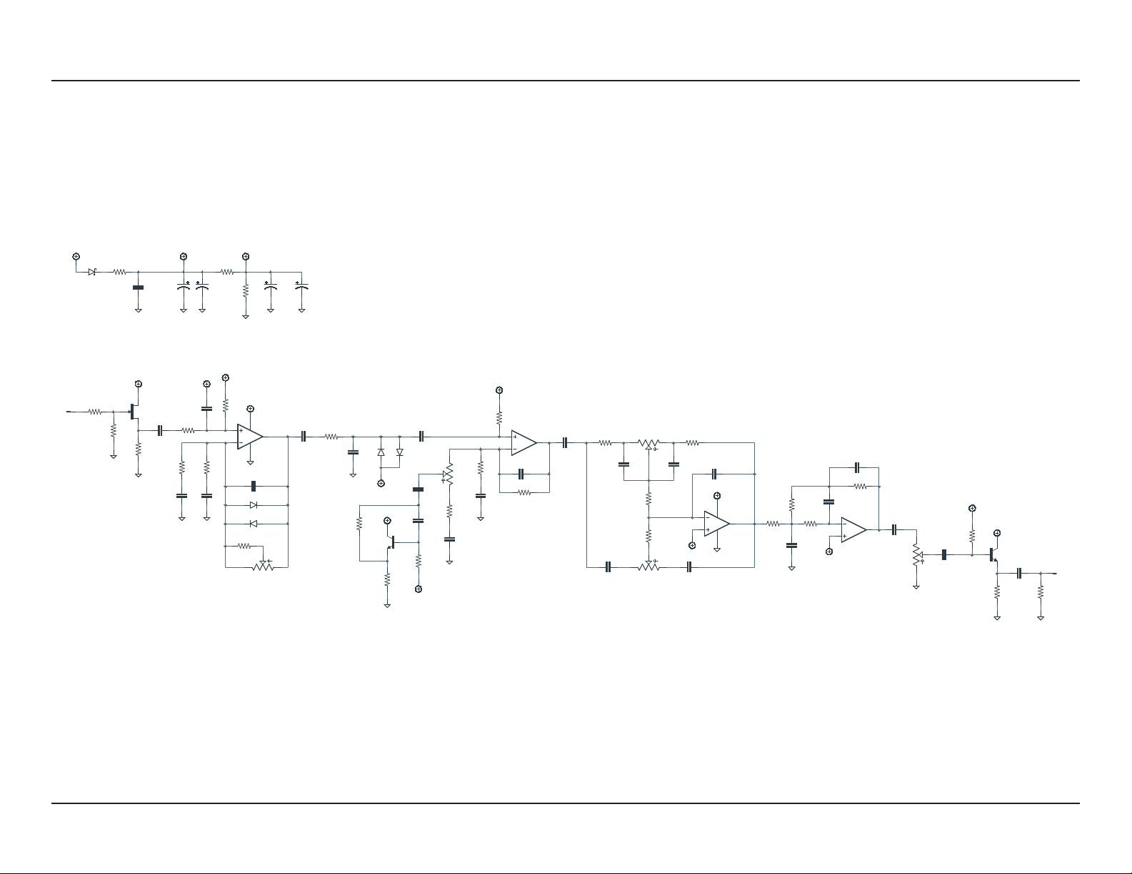
C2 10n Film capacitor, 7.2 x 2.5mm
C3 150pF MLCC capacitor, NP0/C0G
C4 68n Film capacitor, 7.2 x 2.5mm
C5 2.2uF Film capacitor, 7.2 x 5mm Can substitute electrolytic (polarity is marked on PCB).
C6 2.2uF Film capacitor, 7.2 x 5mm
C7 3n9 Film capacitor, 7.2 x 2.5mm
C8 2.2uF Film capacitor, 7.2 x 5mm
C9 330pF MLCC capacitor, NP0/C0G
C10 12n Film capacitor, 7.2 x 2.5mm
C11 56n Film capacitor, 7.2 x 2.5mm
C12 2n7 Film capacitor, 7.2 x 2.5mm
C13 1uF Film capacitor, 7.2 x 3.5mm
C14 1uF Film capacitor, 7.2 x 3.5mm
C15 100n Film capacitor, 7.2 x 2.5mm
C16 33n Film capacitor, 7.2 x 2.5mm
C17 1n8 Film capacitor, 7.2 x 2.5mm
C18 18n Film capacitor, 7.2 x 2.5mm
C19 8n2 Film capacitor, 7.2 x 2.5mm
C20 22n Film capacitor, 7.2 x 2.5mm
C21 1n Film capacitor, 7.2 x 2.5mm
C22 82n Film capacitor, 7.2 x 2.5mm
C23 1uF Film capacitor, 7.2 x 3.5mm
C24 100n Film capacitor, 7.2 x 2.5mm
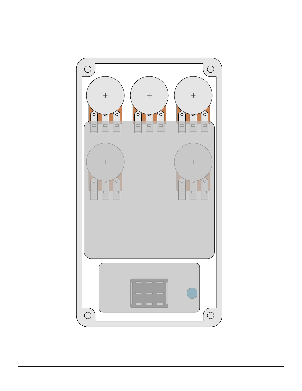
C25 3.3uF Film capacitor, 7.2 x 5.5mm Can substitute electrolytic (polarity is marked on PCB) or use 1uF.
C26 220uF Electrolytic capacitor, 6.3mm Power supply filter capacitor.
C27 47uF Electrolytic capacitor, 5mm Power supply filter capacitor.
C28 220uF Electrolytic capacitor, 6.3mm Power supply filter capacitor.
C29 220uF Electrolytic capacitor, 6.3mm Power supply filter capacitor.
C30 100n MLCC capacitor, X7R Power supply filter capacitor.
Z1 1N5232B Zener diode, 5.6V, DO-35
D1 1N5817 Schottky diode, DO-41
D2 1N914 Fast-switching diode, DO-35
D3 1N914 Fast-switching diode, DO-35
D4 Germanium Germanium diode, DO-7 Any germanium diode should work about the same in this circuit, so
use whatever you can find.
D5 Germanium Germanium diode, DO-7
Q1 2N5457 BJT transistor, NPN, TO-92 Substitute. Original uses BF245C.
Q2 2N5088 Operational amplifier, dual, DIP8 Substitute. Original uses 2SC3198-BL.

ARCTURUS NATURAL OVERDRIVE 5
PARTS LIST, CONT.
PART VALUE TYPE NOTES
Q3 2N5088 BJT transistor, NPN, TO-92 Substitute. Original uses 2SC3198-BL.
IC1 RC4558P Operational amplifier, dual, DIP8
IC1-S DIP-8 socket IC socket, DIP-8
IC2 RC4558P Operational amplifier, dual, DIP8
IC2-S DIP-8 socket IC socket, DIP-8
DRIVE 500kA 16mm right-angle PCB mount pot
LOW 50kB 16mm right-angle PCB mount pot
MID 25kC 16mm right-angle PCB mount pot Original uses 30kC. 25kC will work the same.
HIGH 50kB 16mm right-angle PCB mount pot
LEVEL 50kA 16mm right-angle PCB mount pot
LED 5mm LED, 5mm, red diffused
IN 1/4" mono 1/4" phone jack, closed frame Switchcraft 111X or equivalent.
OUT 1/4" mono 1/4" phone jack, closed frame Switchcraft 111X or equivalent.
DC 2.1mm DC jack, 2.1mm panel mount Mouser 163-4302-E or equivalent.
FSW 3PDT Stomp switch, 3PDT
ENC 125B Enclosure, die-cast aluminum Can also use a Hammond 1590N1.

ARCTURUS NATURAL OVERDRIVE 6
BUILD NOTES
Germanium diode selection
Based on the factory schematic, the original ODR-S seemed to use AA-112 germanium diodes. However,
according to the designer, this was just a placeholder from the schematic software and not the actual
type used in production. He does mention that Nobels eventually switched to a type of diode that he
found to be inferior because they weren’t able to find enough supply of his preferred type, so at least
according to him, the type makes a difference.
If you’re curious, Kai Tachibana has written an article about the development of the ODR-S that’s a very
interesting read.
IC2A bias
IC2A has an odd bias arrangement in the original ODR-S circuit, getting its bias voltage through the
one of the germanium diodes instead of from a bias resistor as you’d expect. This may have been
an intentional choice and it’s possible that it leads to a desirable effect—but from an engineering
standpoint, it looks like a mistake.
We’ve corrected this by adding a capacitor (C8) between the diodes and the IC2A input and adding a
separate bias resistor (R10) at the input. We chose 43k because it’s the value used in the ODR-1. If you
want to omit this, just jumper C8 by running a wire between the pads and omit R10 (leave it empty).
In the ODR-CS, this whole stage has been redesigned so that the midrange control can cut as well as
boost, so we can’t infer whether the designer would see this as a mistake today upon revisiting the
circuit. However, the fact that the IC no longer gets its bias from the diode would indicate that he does
not see it as critical to the sound.
Be aware that if you want to put the hard-clipping diodes on a switch, the op-amp will not bias if they’re
switched out unless you include our C8/R10 fix.
Midrange pot value
The midrange pot is 30kC on the original ODR-S. This value is basically impossible to find without
custom-ordering in large quantities, so just use 25kC or even 20kC.

SCHEMATIC
ARCTURUS NATURAL OVERDRIVE 7
IN
OUT
1N914
1N34A
1N5817
220uF
50kA
50kB500kA
50kB
25kC
+9V
100n
GND
33k
1M
2N5457
3k3
GND
GND
VA
VA
68n
2k7
10n
10k
10k
10k
220uF
47R
VB
GND
GND
VB
VB
RC4558P
VA
GND
RC4558P
RC4558P
RC4558P
VA
GND
150pF
1k
1k
1k8
68n
GNDGND
2.2uF
2.2uF
10k
3n9
GND
330pF
22k
12k
12n
GND
47k
56n
2n7
200k
VB
1k5
2N5088
VA
3k3
GND
1uF
GND
1uF
22k 10k
5k62k4
100n 33n
1n8
VB
18n 8n2
5k6
22n
4k7
10k
1n
GND
15k
VB
82n
1uF
GND
100n
200k
2N5088
VB
VA
2k2
GND
3.3uF
200k
GND
220uF
GND
47uF
GND
VB
43k
2.2uF
VB
D1
C29
LEVEL
1
2
3
1
2
3
HIGH
1
2
3
DRIVE
LOW
1
2
3
1
2
3
MID
C30
R1
R2
Q1
R3
C1 R4
C2
R5
R28
R29
C26
R30
2
3
1
IC1A
84
2
3
1
IC2A
6
5
7
IC2B
84
6
5
7
IC1B
C3
D2
D3
R6
R7
R8
C4C5
C6
R9
C7
D4
D5
C9
R11
R12
C10
R13
C11
C12
R14
R16
Q2
R15
C13
C14
R17 R18
R19R20
C15 C16
C17
C18 C19
R21
C20
R22
R23
C21
R24
C22
C23
C24
R25
Q3
R26
C25
R27
C28 C27
R10
C8
GND

ARCTURUS NATURAL OVERDRIVE 8
DRILL TEMPLATE
Cut out this drill template, fold the edges and tape it to the enclosure. Before drilling, it’s recommended
to first use a center punch for each of the holes to help guide the drill bit.
Ensure that this template is printed at 100% or “Actual Size”. You can double-check this by measuring
the scale on the printed page.
Top jack layout assumes the use of closed-frame jacks like the Switchcraft 111X. Open-frame jacks will
not fit in layouts with 5 or more knobs due to the placement of the DC jack.
LED hole drill size assumes the use of a 5mm LED bezel, available from several parts suppliers. Adjust
size accordingly if using something different, such as a 3mm bezel, a plastic bezel, or just a plain LED.
ø3/8” ø1/2”
0.385”
0.625” 0.625”
x: -0.775, y: +1.71 x: +0.775, y: +1.71
ø9/32” ø9/32”
x: +0.775, y: +0.41
ø9/32”
x: 0, y: -1.775
ø15/32”
x: -0.775, y: -1.775
ø5/16”
CENTER (0,0)
ø3/8”
125B
OUT
LOW
x: -0.775, y: +1.71
ø9/32”
MID HIGH
x: -0.775, y: +0.41
ø9/32”
LEVEL DRIVE
FOOTSWITCHLED
DC IN
0 1 2
CM
0 1
INCH

ARCTURUS NATURAL OVERDRIVE 9
ENCLOSURE LAYOUT
Enclosure is shown without jacks. See next page for jack layout and wiring.
125B

ARCTURUS NATURAL OVERDRIVE 10
WIRING DIAGRAM
125B
IN +VGND NC NC OUT
PCB
IN
GND +V +V JACK GND JACK
OUTIN
GND GND PCB
OUT

ARCTURUS NATURAL OVERDRIVE 11
LICENSE & USAGE
No direct support is offered for these projects beyond the provided documentation. It’s assumed
that you have at least some experience building pedals before starting one of these. Replacements and
refunds cannotbe offered unless it can be shown that the circuit or documentation are in error.
All of these circuits have been tested in good faith in their base configurations. However, not all the
modifications or variations have necessarily been tested. These are offered only as suggestions based
on the experience and opinions of others.
Projects may be used for commercial endeavors in any quantity unless specifically noted. No
attribution is necessary, though a link back is always greatly appreciated. The only usage restrictions
are that (1) you cannot resell the PCB as part of a kit without prior arrangement, and (2) you cannot
“goop” the circuit, scratch off the screenprint, or otherwise obfuscate the circuit to disguise its source.
(In other words: you don’t have to go out of your way to advertise the fact that you use these PCBs, but
please don’t go out of your way to hide it. The guitar effects industry needs more transparency, not less!)
DOCUMENT REVISIONS
1.0.0 (2023-09-08)
Initial release.
Table of contents
Other aion Music Pedal manuals