Air Comm Systems ACS 296 User manual

Air Comm Systems Inc.
1640 W. Acoma Blvd., Suite A-118
Lake Havasu City, AZ 86403
Phone (928) 854-5402
FAX (928) 854-8919
E-Mail aircomminc@aol.com
Air Comm Systems, Inc.
Receive Audio Indicator Panel
Installation Manual
ACS 296 Revision 1.1
AirComm
Airborne Audio Products

Air Comm Systems, Inc. Page 2
n
Installation
General Operating Specifications Page 3
Physical Dimensions Page 4
Interface Schematic Page 5
n
Instructions for Continued Airworthiness
Page 6
n
Warranty Information
Air Comm Systems Warranty Page 7
n
Supplemental Information
Product Schematics
ACS 296 Installation Manual
Table of Contents

Air Comm Systems, Inc. Page 3
n
Operating Specifications
ACS 296 Installation Manual
General Operating Specifications
Audio Input: Up to 6 audios
Duty Cycle: Continuous
Power Requirements: 28V DC +/- 10%
Maximum Operating Altitiude: 22,000 ft.
Operating Temperature Range: -40 C to +85 C (operating), -65 C to +125 C (storage)
Current Drain: 100mA minimum; 750 mA maximum
n
Unit Description
The ACS 296 Receive Audio Indicator Panel is a compact, Dzus mounted unit that provides a
visual status of which receive audios are active in the aircraft audio system. The ACS 296 is
designed to be interfaced with a Single or Dual Channel Audio Mixer Panel and installed in close
proximity to that panel for easy reference by the user.
n
Method of Operation
The ACS 296 senses the incoming receive audios and displays the active status on the the front
panel. The active status is indicated by a glowing green LED. The intensity of the indicator is
controlled by a photo sensor located on the front of the ACS 296; as the ambient light conditions
change in the cockpit or cabin, so will the LED intensity.
n
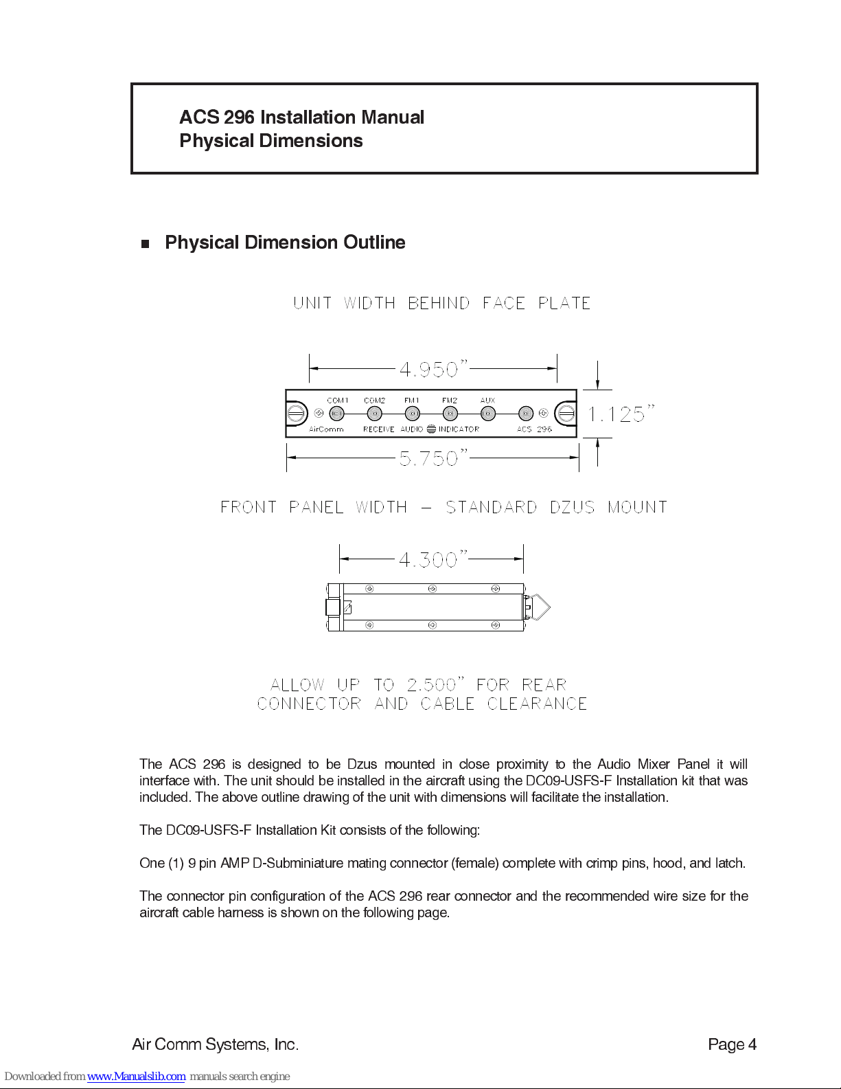
Physical Specifications
Size: 5.75 in. (14.61 cm) W Weight: .75 lb. (0.38 kg)
1.125 in. ( 2.86 cm) H
4.30 in. (10.92 cm) D
Illumination: Edge lit front panel per MIL-P-7738E,type 5. Capable of connection to
dimmer bus for adjustment. RX Status indicators are 5.0V Green LEDs.
Mounting: Standard Dzus rail mount, two (2) fasteners
Controls: None

Air Comm Systems, Inc. Page 4
The ACS 296 is designed to be Dzus mounted in close proximity to the Audio Mixer Panel it will
interface with. The unit should be installed in the aircraft using the DC09-USFS-F Installation kit that was
included. The above outline drawing of the unit with dimensions will facilitate the installation.
The DC09-USFS-F Installation Kit consists of the following:
One (1) 9 pin AMP D-Subminiature mating connector (female) complete with crimp pins, hood, and latch.
The connector pin configuration of the ACS 296 rear connector and the recommended wire size for the
aircraft cable harness is shown on the following page.
n
Physical Dimension Outline
ACS 296 Installation Manual
Physical Dimensions

Air Comm Systems, Inc. Page 5
The ACS 296 wiring harness should be constructed of Tefzel aircraft wire (M22759/16 grade). Power
and ground wires should be 22 AWG. Shielded wires should be used where noted. Adequate protection
against wear and chafing should be taken by using a braided cable sleeving or jacket. Before
completing installation, verify that all cable connector pins are seated properly and that the connector is
securely mounted to the unit mating connector.
Pre-fabricated cable harnesses are available from Air Comm to expedite installation consult our
sales department for details.
n
Connector Schematic
ACS 296 Installation Manual
Interface Schematic

Air Comm Systems, Inc. Page 6
Instruction for continued airworthiness forReceive Audio Indicator Panel Model ACS-296.
GENERAL DESCRIPTION:
The ACS 296 Receive Audio Indicator Panel is a compact, Dzus mounted unit that provides a
visual status of which receive audios are active in the aircraft audio system. The ACS 296 is
designed to be interfaced with a Single or Dual Channel Audio Mixer Panel and installed in close
proximity to that panel for easy reference by the user.
PURPOSE:
To provide instructions for the maintenance and inspection of the Air Comm Systems, Inc. Model
ACS-296 Receive Audio Indocator Panel.
This Manual provides instructions supplementing the aircraft maintenance manual. These
instructions only supersede the aircraft manual in the indicated areas.
OPERATIONAL CHECK:
The Receive Audio Indicator Panel should be checked prior to first flight each day per current
operations manual.
MAINTENANCE:
Check security and condition of Dzus mounted panel(s), check associated wiring hareness at
periodic inspections such as annual/100 hour IAW FAR43 Appendix D(i).
On Condition.
Send Receive Audio Indicator Panels to qualified repair facility for any repairs. Contact Air Comm
Systems, Inc. Phone 909-0824-8860 or FAX 909-824-8862 for nearest factory authorized
repair facility.
ACS 296 Installation Manual
Continued Airworthiness Insrtuctions

Air Comm Systems, Inc. Page 7
n
Warranty Information
ACS 296 Installation Manual
Warranty Information
Air Comm Systems, Inc. warrants each new product to be free from defective material and
workmanship and agrees to remedy any defect or to furnish a new part in exchange for any defective
unit provided an examination discloses such defect occurred under normal use and service, and
provided the defective unit is delivered to us, with transportation charges prepaid, within 1 year from the
date of acceptance of equipment by the owner. Each unit required and claimed defective must be
returned to:
Air Comm Systems, Inc.
11640 W. Acoma Blvd., Suite A-118
Lake Havasu City, AZ 86403
Attn: Service Dept.
Phone (928) 854-5402
FAX (928) 854-891
E-Mail aircomminc@aol.com
This warranty does not extend to any products which have been subjected to misuse, neglect, accident,
or in violation of instructions furnished, nor does it extend to units which have been repaired or altered
outside of our factory except where such repairs are specifically authorized in writing by us.This
warranty is in lieu of all other warranties expressed or implied, and no representative or person is
authorized to assume for us any other liability in connection with the sale of our products.
Popular Control Panel manuals by other brands

Trikdis
Trikdis SP231 user manual

Vallox
Vallox 280 L Technical specifications

Fire-Lite Alarms
Fire-Lite Alarms FIRE COMMAND 25 Installation and operating instruction manual

BFT
BFT LIBRA-C-LX installation manual

WAREMA
WAREMA Climatronic 3 Series Commissioning / Setting instructions

Secutron
Secutron MGC MIX-4000 Series Installation and operation manual