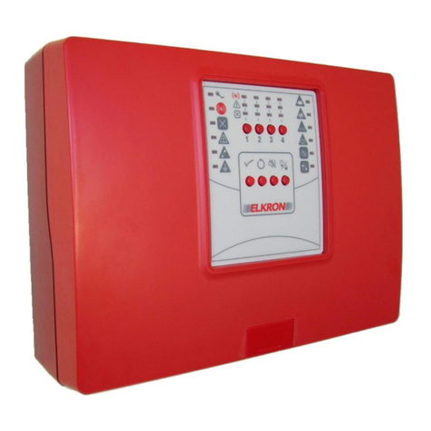
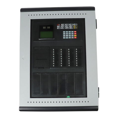
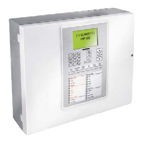
Elkron C420 Owner's manual

1/24 Installazione MP508
DS80SC86-006A LBT80744
Programming Manual
C420
4 –20 zones
Conventional control panel
GB
0051

2 C420 Programming Manual
The information contained in this document has been collected and controlled carefully. However, the company cannot be held
responsible for any possible errors and omissions.
The company reserves the right to make, at any time and without warning, improvements and modifications to the products
described in this manual.
In this manual, you may find references and information about products (hardware or software) or services not commercialized yet.
These references and information do not imply that the company intends to commercialize these products and services.
Elkron is a trademark of URMET S.p.A.
All trademarks mentioned in this document belong to the corresponding owners.
All rights reserved. The total or partial reproduction of this document is authorised only for installation purposes of the C420
System.
Tel. +39 011.3986711 –Fax +39 011. 3986703

C420 Programming Manual 3
TABLE OF CONTENTS
TABLE OF CONTENTS...................................................................................................................................................................... 3
1GENERAL DESCRIPTION........................................................................................................................................................... 4
1.1 INTRODUCTION................................................................................................................................................................... 4
1.2 ALARMS AND TYPES OF ZONE.......................................................................................................................................... 4
2LED INDICATORS –KEYS –RELAYS....................................................................................................................................... 6
2.1 LED INDICATORS ................................................................................................................................................................ 6
2.2 KEYS..................................................................................................................................................................................... 7
2.2.1 Internal keyboard......................................................................................................................................................... 7
2.2.2 External keyboard........................................................................................................................................................ 8
2.3 OUTPUTS AND RELAYS...................................................................................................................................................... 8
3MAIN MENU................................................................................................................................................................................. 9
3.1 LANGUAGE ........................................................................................................................................................................ 10
3.2 PROGRAMMING................................................................................................................................................................. 10
3.2.1 Password................................................................................................................................................................... 10
3.2.2 System name............................................................................................................................................................. 11
3.2.3 Zones......................................................................................................................................................................... 11
3.2.4 Outputs and Relays ................................................................................................................................................... 14
3.2.5 Timers........................................................................................................................................................................ 16
3.2.6 Cards initialization...................................................................................................................................................... 16
3.2.7 Printer ........................................................................................................................................................................ 17
3.2.8 LCD annunciator........................................................................................................................................................ 17
3.3 SERVICE............................................................................................................................................................................. 18
3.3.1 Event log.................................................................................................................................................................... 18
3.3.2 Print Event Log .......................................................................................................................................................... 18
3.3.3 Clock.......................................................................................................................................................................... 19
3.3.4 Zone test.................................................................................................................................................................... 19
3.3.5 Batteries test.............................................................................................................................................................. 20
3.3.6 FW revision................................................................................................................................................................ 20
3.4 EXCLUSIONS ..................................................................................................................................................................... 21
3.4.1 Zones......................................................................................................................................................................... 21
3.4.2 Supplementary siren outputs ..................................................................................................................................... 21
3.4.3 Siren output................................................................................................................................................................ 21
3.4.4 Printer ........................................................................................................................................................................ 22
3.4.5 LCD annunciator........................................................................................................................................................ 22

4 C420 Programming Manual
1 GENERAL DESCRIPTION
1.1 INTRODUCTION
C420 is a modular conventional control panel which can handle from 4 (basic configuration) up to max 20 detection circuits (via
optional circuit modules) where it is possible to connect up to 512 points.
Each circuit covers a zone which can house up to 32 conventional points (the control panel, though, has to be compliant with the
constraint of max 512 total points in the field).
Each zone is permanently associated to a dedicated relay which is activated when the zone goes to alarm condition.
Moreover, the control panel is equipped with the following outputs and relays:
one cumulative alarm relay output
one cumulative siren relay output
one cumulative fault relay output
one programmable relay output activated as a consequence of lack of AC mains or presence of at least one exclusion
one supervised siren output
four supplementary supervised siren outputs, available on an optional module, which can be associated independently of
each other to one or more zones.
The control panel is equipped with an alphanumeric 4X40 display and a 12 keys keyboard. Moreover, an external PS2 keyboard
can be connected to the control panel in order to ease the input during the programming phase.
By using an optional interface card, the control panel can be connected to a remote LCD annunciator which shows the contents of
the display during the monitoring phase and a printer with Centronics interface for event log printing.
The control panel is equipped with an event log able to store up to 1000 events.
Also, there is a clock with battery backup for keeping date and time updated even when the control panel is powered off.
The control panel can house internally two 12V-12Ah (RB1212 type) batteries (sold separately).
1.2 ALARMS AND TYPES OF ZONE
The control panel can switch into the following alarm conditions:
Alarm with siren output OFF
Alarm with siren output ON
Master alarm
Each alarm condition is characterized by the following configuration of outputs and user signalling (LED, buzzer):
STATE
ALARM
Buzzer
Alarm
LED
Alarm
relay
Siren
relay
Siren
output
with siren output OFF
ON
OFF
ON
OFF
OFF
with siren output ON
ON
ON
ON
ON
ON
master alarm
ON
ON
ON
ON
ON
The alarm condition of the control panel depends on the alarm condition of the zones and the presence of the master alarm
condition.
Each zone can be in one of the following alarm conditions, depending on its programming mode and the number of points in alarm
condition:
Alarm with siren output OFF
Alarm with siren output ON

C420 Programming Manual 5
The control panel is in the state of
Alarm with siren output OFF when
oat least one zone is in alarm condition with siren output OFF
ono zone is in alarm condition with siren output ON
othe master alarm condition is not present
Alarm with siren output ON when
oat least one zone is in alarm condition with siren output ON
othe master alarm condition is not present
Master alarm when
othe user pushes the relevant key on the keyboard or a zone programmed to trigger the master alarm condition
goes to alarm with siren output ON.
The alarm condition of the zones and the control panel involves the activation of the zone relays and the supplementary siren
outputs (if present) as follows:
If the control panel is in master alarm condition, all the zone relays and all the supplementary siren outputs are activated
If the control panel is not in master alarm condition, the alarm condition of each zone is taken into account:
oif the zone is in alarm condition with siren output OFF, the zone relay is activated if it has been programmed to
be activated in this condition
oif the zone is in alarm condition with siren output ON, the zone relay and the supplementary siren outputs
associated to the zone are activated.
Each zone can be programmed in one of the following operating modes:
Single knock
When the zone is in idle condition and the circuit detects an alarm from one or more points, it switches
to alarm condition with siren output ON.
Single knock with
delay (*)
When the zone is in idle condition and the circuit detects an alarm from one or more points, it switches
to alarm condition with siren output OFF and an activation timer starts. When the timer expires, the zone
switches to alarm condition with siren output ON.
Double knock
When the zone is in idle condition and the circuit detects an alarm from one point, it switches to alarm
condition with siren output OFF. When the same circuit detects an alarm from another point, the zone
switches to alarm condition with siren output ON.
Double knock with
delay (*)
When the zone is in idle condition and the circuit detects an alarm from one point, it switches to alarm
condition with siren output OFF. When the same circuit detects an alarm from another point, an
activation timer starts. When the timer expires, the zone switches to alarm condition with siren output
ON.
Hotel (*)
When the zone is in idle condition and the circuit detects an alarm from one or more points, it switches
to alarm condition with siren output OFF and an activation timer starts. If the same circuit detects an
alarm from another point before the timer expires, the residual timer is compared with the hotel reload
timer. If the residual timer is higher than the hotel reload timer, the latter is loaded in the residual timer.
In any case, when the residual timer expires the zone switches to alarm condition with siren output ON.
(*) In the modes with delay, it is possible:
to increment, by pressing the INCREASE DELAY key, the siren output activation timer;
to clear immediately, by pressing the SKIP DELAY key, the siren output activation timer.

6 C420 Programming Manual
2 LED INDICATORS –KEYS –RELAYS
2.1 LED INDICATORS
The control panel is equipped with the following LED indicators, used to signal alarm conditions, faults, exclusions, etc.
Each LED is represented by an icon on the front cover of the control panel. Just for convenience, a name is associated to each
LED. This name will be used to refer to the LED throughout the document.
ICON
NAME
COLOUR
FUNCTION
AC / BATTERY
GREEN
Steady ON: the control panel is power supplied through the AC mains.
Blinking: the control panel is power supplied through the batteries.
Steady OFF: the command and control module is faulty.
ALARM
RED
Steady ON: the control panel is in alarm condition with siren output
ON.
GENERAL EXCLUSION
YELLOW
Steady ON: at least one exclusion is present.
This indicator provides a cumulative notification of exclusions.
GENERAL FAULT
YELLOW
Steady ON: at least one fault is present.
This indicator provides a cumulative notification of faults. Further
details on the fault type are provided through the display or dedicated
LEDs.
CPU
SYSTEM FAULT
YELLOW
Steady ON: a system fault is present.
Usually, when this LED is turned ON the CPU stops working properly
because of an hardware problem (e.g., some peripheral stops working
as expected) or a serious malfunctioning of the program.
BATTERY FAULT
YELLOW
Steady ON: a fault or a malfunctioning of the batteries of the control
panel occurs.
\
BATTERY CHARGER
FAULT
YELLOW
Steady ON: a fault to the battery charger has occurred.
FUSE FAULT
YELLOW
Steady ON: a fault to a fuse has occurred.
SIREN FAULT
YELLOW
Steady ON: the line connected to a siren output is in fault (because of
missing end of line resistor, short circuit or fuse fault).
GROUND DISPERSION
YELLOW
Steady ON: an electric ground dispersion is present.
SIREN EXCLUDED
YELLOW
Steady ON: at least one siren output is excluded.
TEST
YELLOW
Steady ON: a zone test is active.

C420 Programming Manual 7
2.2 KEYS
2.2.1 Internal keyboard
The table below describes the keys of the internal keyboard of the control panel and their function. An icon on the front panel of the
control panel is associated to each key. Just for convenience, a name is associated to each key as well. These names will be used
throughout the document to refer to each key.
ICON
NAME
FUNCTION
INCREASE DELAY
When this key is pressed, the running activation delay of the siren outputs is incremented
by 1 minute.
The overall maximum value for the delay, composed of the sum between the initial
programmed delay and the delay added through this key, is 10 minutes.
If the passwords are enabled, the user is required to enter the level 2 password.
The usage of this key leads to the storage of an event in the event log.
SKIP DELAY
This key zeroes the running activation delay of the siren outputs.
By pressing this key, the zones for which the delay is running switch immediately to the
alarm condition with siren output ON.
SILENCE/REARM
SIRENS
This key silences the active siren outputs and rearms the siren outputs previously silenced.
If the passwords are enabled, the user is required to enter the level 2 password.
The usage of this key leads to the storage of an event in the event log.
MASTER ALARM
This key triggers a master alarm condition.
If the passwords are enabled, the user is required to enter the level 2 password.
The usage of this key leads to the storage of an event in the event log.
TEST LAMP
This key starts the test lamp procedure, which activates the buzzer and turns all the LEDs
ON simultaneously, for a period of 3 seconds.
If the key UP is pressed during the execution of the test, when it ends the user enters a
screen which makes it possible to regulate the sharpness of the display.
GLOBAL RESET
This key starts the “global reset” procedure. This procedure clears any alarm and fault
event and restores the outputs and relays in idle state.
If the control panel is in the monitoring phase and the passwords are enabled, the user is
required to enter the level 2 password.
The usage of this key leads to the storage of an event in the event log.
If before pressing the GLOBAL RESET key there was any alarm or fault and the causes of
these events are still present after the reset, the events will be detected again.
UP,
DOWN,
LEFT,
RIGHT
Direction arrows, used to move through the menu items and to scroll the list of characters
when entering numbers and strings.
ESC/MENU
If this key is pressed when the control panel is in the monitoring phase, the main menu is
displayed (MENU).
In all the other circumstances, this key is used to leave the screen/menu currently
displayed and return to the previous screen/menu (ESC).
ACK
By pressing this key (this operation is named “event acknowledgement”) the buzzer stops
sounding.
This key is also used to confirm the user input in the menus where numbers and strings are
entered.

8 C420 Programming Manual
2.2.2 External keyboard
A PS2 keyboard can be connected to the control panel. In particular, this keyboard is convenient during the programming phase,
when the user is required to input numbers and strings.
The table below reports the keys used in the PS2 keyboard and the associated function.
KEY
FUNCTION
F1
GLOBAL RESET (*)
F2
SILENCE/REARM SIRENS (*)
F3
INCREASE DELAY (*)
F4
SKIP DELAY (*)
F5
TEST LAMP (*)
F6
MASTER ALARM (*)
F7
MENU/ESC (*)
F8
ACK (*)
F9
Decrease sharpness of display
F10
Increase sharpness of display
ESC
This is handled as the ESC function of the MENU/ESC key of the internal keyboard: this key is used to leave
the screen/menu currently displayed and return to the previous screen/menu.
SPACE BAR
This is handled as the RIGHT key of the internal keyboard: typically, it is used to insert a space during the
input of strings.
BACKSPACE
This is handled as the LEFT key of the internal keyboard: typically, it is used during the input of strings to
delete the last inserted character and bring the cursor back to the previous character.
Alphanumeric
characters
They can be used to enter characters directly during the input of names, numbers, passwords, etc.
SHIFT LEFT,
SHIFT RIGHT
Activation of capital letters.
CAPS LOCK
Permanent activation of capital letters.
BLOCK NUM
Activation of the numbers on the numeric keypad.
ENTER
This is used to confirm the input of
names
set of passwords
numbers
date and time
LEFT, RIGHT,
UP, DOWN
arrows
They perform the same function of the keys LEFT, RIGHT, UP, DOWN available on the internal keyboard.
(*) see the previous paragraph.
2.3 OUTPUTS AND RELAYS
The table below describes the outputs and relays available in the control panel.
OUTPUT/RELAY
FUNCTION
ALARM RELAY
This relay is activated when the control panel switches to alarm condition with siren output OFF
or ON.
The relay is deactivated when a “Global Reset” procedure is executed.
SIREN RELAY
This relay is activated when the control panel switches to alarm condition with siren output ON.
The relay is deactivated when a “Global Reset” procedure is executed.
FAULT RELAY
This relay is deactivated when the control panel detects a fault. The relay is activated again
when a “Global Reset” procedure is executed.
The relay is deactivated also if the CPU board gets faulty.
PROGRAMMABLE RELAY
This relay can be associated to either one of the following functions:
Exclusion relay
The relay is activated when at least one exclusion is present
AC mains relay
The relay is activated when the control panel detects the lack of AC mains.
It is deactivated when a “Global Reset” procedure is executed.
It is possible to associate an activation delay to the relay.
ON-BOARD SIREN OUTPUT
The siren output handles a supervised output to activate fire alarm signalling equipments (sirens,
bells, etc.).
SUPPLEMENTARY SIREN
OUTPUTS
The supplementary siren outputs, available on an external expansion card, are supervised
outputs and can be used to activate fire alarm signalling equipments (sirens, bells, etc.).
Each of these outputs can be associated independently of each other to one or more zones.

C420 Programming Manual 9
3 MAIN MENU
When the control panel is in monitoring phase and the MENU/ESC key is pressed, the following main menu is displayed:
When this menu is displayed, the control panel is still monitoring the field. By pressing LEFT or ESC/MENU, the monitoring screen
is shown again. By pressing RIGHT, the currently selected menu is entered.
Before describing each item in a detailed way, a few general considerations valid for each menu are reported below:
Browsing through the menus
The UP/DOWN keys move the selector through the menu items.
The LEFT key brings back the previous menu, while by pressing the RIGHT key the currently selected element is accessed.
In a few specific cases (e.g., during input of numbers and strings), ACK confirms the entered characters while MENU/ESC
quits the input screen and brings back to the previous menu.
When a menu requires the setting of a configuration option (e.g., selection of a parameter, inclusion/exclusion of an
element, etc.), when the menu is entered the selector selects the current value of the option; the user, then, is allowed to
select the desired option by using the keys UP/DOWN and finally confirm the choice by pressing the RIGHT key.
Password input
The user is required to enter the password whenever a password protected menu or functionality is entered and the passwords are
enabled.
In such a case, the control panel shows the following message:
PASSWORD:_
Initially, the cursor selects the first digit (visible) to be inserted. By pressing the UP/DOWN keys, the user selects the digit. By
pressing RIGHT, the inserted digit is confirmed and the cursor selects the next digit. The digits already selected and confirmed are
replaced by asterisks.
PASSWORD:*_
After entering the fourth digit (all the passwords have a 4 digits fixed length), press RIGHT to confirm the password input. If the
password is correct, the menu/functionality is accessed, otherwise the control panel goes back to the previous menu.
During the input phase, the LEFT key deletes the character on the left of the cursor and moves the cursor to the previous
character. If the cursor is selecting the first character, the LEFT key brings back to the previous menu.
Number input
When the user is required to enter a number (e.g., a zone number, a timer value, etc.), the following message is displayed:
XXXXXX: _
where XXXXXX is a string indicating the number to be inserted.
The user must insert the value of each of the digits the number is composed of, by using the following keys:
UP/DOWN: scroll the characters 0, 1, … , 9 to assign the desired value to the single digit
LEFT/RIGHT: move through the digits which compose the number
MENU/ESC: quit the input and discard the entered modifications
ACK: confirm the entered number
After having confirmed the input by pressing ACK, the entered number is compared with a set of allowed values and, if it is not
valid, the user is required to enter the number again.
String input
When the user is required to enter a string (e.g., the system name or a name of a zone), the following message is displayed:
XXXXXX: _
XXXXXX is an auxiliary string indicating the string/name to be inserted.
> LANGUAGE
PROGRAMMING
SERVICE
EXCLUSIONS

10 C420 Programming Manual
The user must enter each of the characters the string is composed of by using the following keys:
UP/DOWN: scroll the characters A, B, …, Z, 0, 1, …, 9, a, b, …, z, SPACE to assign a value to the character in the current
position of the cursor
LEFT: delete the character on the left of the cursor and move the cursor back to the previous position
RIGHT: confirm the character on the current position of the cursor and move the cursor to the next position
ESC: quit the string input and discard the modifications
ACK: the entered string is confirmed
NOTE: the information described above does not apply to the input of the reference passwords, for which the reader is invited to
refer to the relevant section.
3.1 LANGUAGE
By selecting ‹‹LANGUAGE›› from the main menu, the menu which allows the user to select the language is shown.
If the passwords are enabled, before accessing this menu the user is required to enter the level 3 password.
For instance, this menu could be shown as follows:
When the menu is entered, the selection character “>“ selects the currently selected language.
A different language is selected by using the UP/DOWN keys and confirmed by pressing the RIGHT key.
3.2 PROGRAMMING
The programming menu, protected by level 3 password input if the passwords are enabled, allows the user to access to the
programming options of the control panel.
When the control panel enters the programming phase, the detection circuits are turned off and any currently active alarm or fault
event is deleted.
The programming menu is composed of the following items (shown in 2 separate screens):
3.2.1 Password
By selecting ‹‹PASSWORD›› from the programming menu, the following menu is displayed:
By selecting ‹‹ENABLE››, the following menu is displayed (when the menu is entered, the selection cursor selects the current
setting):
This menu allows the user to enable or disable the password request when the user enters password protected menus and
functionalities. When the control panel is in monitoring phase and the passwords are disabled a fault message is notified.
> ENGLISH
ITALIANO
FRANCAIS
> PASSWORD
SYSTEM NAME
ZONES
OUTPUTS AND RELAYS
> TIMERS
CARDS INITIALIZATION
PRINTER
LCD ANNUNCIATOR
> ENABLE
SET
ENABLE
> YES
NO

C420 Programming Manual 11
By selecting ‹‹SET››, the following menu is displayed:
When the menu is entered, the cursor selects the 1st digit of password 1; by using the UP/DOWN keys, the digits 0-9 are scrolled.
By pressing RIGHT, the cursor moves to the next digit; by pressing LEFT; the cursor moves back to the previous digit.
After inserting the 4th digit of the generic password, by pressing RIGHT the 1st digit of the next password is selected.
The cursor always blinks on the currently selected digit.
To quit the menu and discard the entered modifications, press ESC.
By pressing ACK, the passwords are all confirmed at the same time.
Please, note that the passwords 1 and 2 are the level 2 ones, whereas the passwords 3 and 4 are the level 3 ones.
The factory default passwords are reported in the following table:
Factory default passwords
Password 1
2222
Password 2
2222
Password 3
3333
Password 4
3333
3.2.2 System name
By selecting ‹‹SYSTEM NAME ›› from the programming menu, the following screen is displayed:
The name currently assigned to the system (XXXXXXXXXXXXXXX), with the cursor placed beyond the last character, is shown.
The system name is entered according to the rules described in the section relevant to string input at the beginning of the chapter.
3.2.3 Zones
After selecting ‹‹ZONES›› from the programming menu, the user is required to enter the zone number:
The number to be inserted is composed of 2 digits (the control panel can handle up to 20 zones) and it must be entered by
following the rules described in the section relevant to number input at the beginning of the chapter.
After entering and confirming the number, if it is valid (i.e., it is relevant to a configured zone) the following menu is shown:
PASSWORD
1: XXXX 2: XXXX
3: XXXX 4: XXXX
SYSTEM NAME:
XXXXXXXXXXXXXXXXXX_
ZONE: __
> NAME
MODE
RELAY
INCLUDE/EXCLUDE
VERIFY

12 C420 Programming Manual
3.2.3.1 Name
By selecting this item, the user can enter the name of the zone (if a name has been already assigned to the zone previously, it is
displayed and the cursor blinks beyond the last character).
After having entered the characters which compose the name, ACK confirms the string entered and the previous menu is shown.
By pressing ESC, the previous menu is shown and the inserted modifications are discarded.
3.2.3.2 Mode
By selecting this item, the following menu of choice of working mode of the zone is shown:
Each mode involves the insertion of a set of parameters, according to the table below (*indicates that the parameter must be
specified for the selected mode):
MODE
DELAY
MASTER
ALARM
ALARM
CONFIRMATION
SINGLE KNOCK
*
SINGLE KNOCK WITH DELAY
*
*
DOUBLE KNOCK
*
DOUBLE KNOCK WITH DELAY
*
*
HOTEL
*
*
After having selected the working mode, a sequence of screens is shown for the settings of the parameters associated to the
chosen mode.
DELAY
This is the delay whose expiration makes the zone in alarm with siren output OFF switch to alarm condition with siren output ON.
The valid range for this parameter is 1 –10 minutes.
The delay is inserted through the following screen:
After inserting and confirming the delay by pressing ACK, the screen related to the next parameter for the selected mode is shown.
MASTER ALARM
When this option is enabled, if the zone goes to alarm condition with siren output ON the master alarm is activated (this leads to
the activation of all the zone relays, all the siren outputs, the alarm relay and the siren relay):
Use the UP/DOWN keys to select the activation/deactivation of this option, then confirm the choice by pressing the RIGHT key.
ZONE: XX
NAME: _
> SINGLE KNOCK
SINGLE KNOCK WITH DELAY
DOUBLE KNOCK
DOUBLE KNOCK WITH DELAY
HOTEL
DELAY: XX
MASTER ALARM
> YES
NO

C420 Programming Manual 13
ALARM CONFIRMATION
This screen allows the user to enable the alarm confirmation option for the zone.
T1 is the alarm inhibition timer; T2 is the alarm confirmation timer.
When the zone in idle condition detects an alarm, this is not notified to the user and the zone switches to the alarm inhibition state.
Moreover, the alarm inhibition timer T1 is started. While T1 is running, further alarms detected in the same zone will be ignored.
When the alarm inhibition timer expires, the circuit associated to the zone is reset and the zone moves to the alarm confirmation
state. At the same time, the alarm confirmation timer T2 is started. If a further alarm is detected in the same zone while T2 is
running, the zone switches to alarm condition with siren output ON, otherwise when T2 expires the zone goes back to the idle
condition.
After selecting the activation/deactivation of this option, confirm the choice by pressing RIGHT.
After setting the last parameter for the selected mode, the following menu is shown:
In this menu, the user is asked to confirm or discard the choices made so far (mode and associated parameters).
If the MENU/ESC key is pressed in any screen during the insertion of parameters, the choices entered up to that moment are
discarded and the initial screen related to mode selection is displayed again.
3.2.3.3 Relay
By selecting this item, the following menu is shown. This menu allows the user to associate a triggering event to the activation of
the relay permanently associated to the zone.
When the menu is entered, the selector selects the current association. The zone relay can be activated when the zone goes to
alarm condition with siren output OFF or ON. After choosing the desired option, confirm it by pressing the RIGHT key.
3.2.3.4 Include/Exclude
This menu allows the user to include/exclude a zone:
When this menu is entered, the selector selects the current condition of inclusion/exclusion. After choosing the desired option,
confirm it by pressing the RIGHT key.
3.2.3.5 Verify
Through this item, it is possible to show the current configuration options of a zone. The information to be shown depends on the
mode programmed for the zone.
Accessing to this menu leads to the visualization of the following information:
ALARM CONFIRMATION (EN54-2 7.12.1)
(T1 = 60s T2 = 60s)
> YES
NO
> STORE CONFIGURATION
EXIT WITHOUT STORING
ZONE: XX
RELAY ACTIVE FOR
> ALARM
ALARM WITH OUTPUT SIREN ACTIVE
ZONE: XX
> INCLDED
EXCLUDED
ZONE: XX (zone number)
YYYYYYYYYYYYYYYYYYYYYYYYY (zone name)
INCLUDED (inclusion/exclusion state)
SINGLE KNOCK WITH DELAY (mode)

14 C420 Programming Manual
By pressing the DOWN key, the screen with the current settings of the parameters is displayed (only the parameters related
to the current programming mode are shown):
By pressing UP, the previous screen is shown; by pressing DOWN once again, the following screen with the association of the
zone relay to the triggering condition is displayed:
UP/DOWN keys are used to go back and forth through the screens. By pressing LEFT or MENU/ESC the previous menu is shown.
3.2.4 Outputs and Relays
By selecting this item, the following menu is shown:
3.2.4.1 Siren output
By selecting ‹‹SIREN OUTPUT ››, the correspondent inclusion/exclusion menu is shown (when the menu is entered, the selector
selects the currently active option):
3.2.4.2 Programmable relay
By selecting ‹‹PROGRAMMABLE RELAY››, the following menu is shown:
The programmable relay can be programmed to signal the presence of exclusions or the lack of AC mains.
The selector position when the menu is entered indicates the current programming option of the relay.
By selecting ‹‹NO AC POWER ›› and confirming the selected choice by pressing the RIGHT key, the currently programmed
activation delay is shown and the user can edit its value (range 0 –10 minutes):
If the AC mains is missing, the relay will be activated when the delay programmed through this menu expires.
DELAY: XX
MASTER ALARM: YES/NO
ALARM CONFIRMATION (EN54-2 7.12.1): YES/NO
RELAY ACTIVE FOR
ALARM WITH OUTPUT SIREN ACTIVE
> SIREN OUTPUT
PROGRAMMABLE RELAY
SUPPLEMENTARY SIREN OUTPUTS
SIREN OUTPUT
> INCLUDED
EXCLUDED
PROGRAMMABLE RELAY
> EXCLUSIONS
NO AC POWER
PROGRAMMBLE RELAY
NO AC POWER
DELAY: __

C420 Programming Manual 15
3.2.4.3 Supplementary siren outputs
By using an optional expansion card, the control panel can be equipped with 4 supplementary siren outputs, which can be
associated to one or mode zones independently of each other.
The siren output is activated when at least one of the associated zones goes to alarm with siren output ON.
When the user selects this item and the expansion card is not present, the following message will be displayed:
In such a condition, by pressing MENU/ESC or LEFT the previous menu is shown.
Conversely, if the expansion card is present, the following screen where the user can choose the number of the siren output to
program is displayed:
After choosing the output number (range 1 –4), the following menu is shown:
By selecting the item ‹‹INCLUDE/EXCLUDE››, it is possible to include or exclude the supplementary siren output. The following
menu is displayed (when the menu is entered, the selector selects the currently active option):
The user can include or exclude the supplementary siren output and confirm the desired option with the RIGHT key.
By selecting ‹‹SET››, the following screen is displayed:
In this screen, it is possible to associate the supplementary siren output to the zones of the control panel.
Anytime, the selector selects one of the zones which can be associated to the siren output.
By using the UP/DOWN keys, one of the following characters can be selected:
* : the siren output is associated to the zone
- : the siren output is not associated to the zone
The LEFT/RIGHT keys move the selector back and forth through the zones.
By pressing ESC, the menu is left and the modifications performed till that moment are discarded.
By pressing ACK, the modifications are confirmed and the menu is left.
If the control panel is equipped with more than 12 zones and the selector selects the 12th zone, by pressing the RIGHT key the
associations with the next zones are shown:
EXPANSION CARD NOT PRESENT
SUPPLEMENTARY SIREN OUTPUT: _
SUPPLEMENTARY SIREN OUTPUT: X
> SET
INCLUDE/EXCLUDE
SUPPLEMENTARY SIREN OUTPUT: X
> INCLUDED
EXCLUDED
SUPPLEMENTARY SIREN OUTPUT: x
> Z01:* Z02:* Z03:- Z04:-
Z05:- Z06:- Z07:- Z08:-
Z09:- Z10:- Z11:- Z12:-
SUPPLEMENTARY SIREN OUTPUT: x
> Z13:- Z14:- Z15:- Z16:-
Z17:- Z18:- Z19:- Z20:-

16 C420 Programming Manual
3.2.5 Timers
When this item is selected, the following menu is displayed:
This menu allows the user to set the Alarm Verification timer and the Hotel Reload timer of the control panel.
By selecting the first item, the following screen is displayed:
By selecting the second item, the following screen is displayed:
The value of the timer shown when each of the screens is entered is the value currently set in the control panel.
Then, the user can assign a new value to each timer (range 0 –10, minutes).
When a zone is in alarm condition and the siren output activation delay is running, by pressing the ACK key the Alarm Verification
timer is added to the residual delay. The increment occurs only the first time ACK is pressed. Further pressure of ACK will not
affect the residual delay for the zone.
The Hotel Reload timer is used when a zone programmed in HOTEL mode switches to alarm condition. For further details, please
refer to the section which describes the operating modes of the zones.
3.2.6 Cards initialization
When this menu item is selected, the cards initialization procedure starts. This procedure, which must be performed upon insertion
and removal of cards (circuit expansion cards or the supplementary siren outputs expansion card), makes the control panel able to
recognize insertion of new cards and removal of old ones. The new cards will be initialized and added to the control panel
configuration, whereas the removed ones will be deleted from the configuration.
When the procedure ends, the following summary screen is shown (the optional modules which can be recognized are 4 circuit
expansion cards and 1 supplementary siren outputs expansion card):
Key:
MLn: circuit expansion card
MCC: command and control module
MSIR: supplementary siren output expansion card
*: module present
-: module absent
> ALARM VERIFICATION TIMER
HOTEL RELOAD TIMER
ALARM VERIFICATION TIMER: XX
HOTEL RELOAD TIMER: XX
ML1:* ML2:* ML3:* ML4:*
MCC:*
MSIR:*

C420 Programming Manual 17
3.2.7 Printer
By selecting this menu item, the following menu which allows the user to recognize and configure the printer module is shown.
By selecting ‹‹ENABLE››, one of the following messages is shown:
RECOGNITION ACTIVATED if the module has not been recognized yet,
EQUIPMENT ALREADY ENABLED if the module has been recognized already.
By selecting ‹‹DISABLE››, one of the following messages is shown:
EQUIPMENT DISABLED if the module has been disabled correctly,
EQUIPMENT NOT PRESENT if the module is not present.
By selecting ‹‹INCLUDE/EXCLUDE››, if the module has been enabled and recognized the following menu is shown:
Otherwise, one of the following messages will be shown:
EQUIPMENT NOT PRESENT if the module is not present,
EQUIPMENT TO BE RECOGNIZED if the module has not been recognized yet.
By selecting ‹‹VERIFY››, one of the following messages is shown, depending on the state of the module:
EQUIPMENT TO BE RECOGNIZED if the module has not been recognized yet,
EQUIPMENT ENABLED if the module has been recognized already and is working correctly,
EQUIPMENT NOT PRESENT if the module is not present.
3.2.8 LCD annunciator
By selecting this menu item, the following menu which allows the user to recognize and configure the LCD annunciator is
displayed:
By selecting ‹‹ENABLE››, one of the following messages is shown:
RECOGNITION ACTIVATED if the LCD annunciator has not been recognized yet,
EQUIPMENT ALREADY ENABLED if the LCD annunciator has been recognized already.
By selecting ‹‹DISABLE››, one of the following messages is shown:
EQUIPMENT DISABLED if the LCD annunciator has been disabled correctly,
EQUIPMENT NOT PRESENT if the LCD annunciator is not present.
By selecting ‹‹INCLUDE/EXCLUDE››, if the LCD annunciator has been enabled and recognized the following menu is
shown:
Otherwise, one of the following messages will be shown:
EQUIPMENT NOT PRESENT if the LCD annunciator is not present,
EQUIPMENT TO BE RECOGNIZED if the LCD annunciator has not been recognized yet.
By selecting ‹‹VERIFY››, one of the following messages is shown, depending on the state of the LCD annunciator:
EQUIPMENT TO BE RECOGNIZED if the LCD annunciator has not been recognized yet,
EQUIPMENT ENABLED if the LCD annunciator has been recognized already and is working correctly,
EQUIPMENT NOT PRESENT if the LCD annunciator is not present.
> ENABLE
DISABLE
INCLUDE/EXCLUDE
VERIFY
PRINTER
> INCLUDED
EXCLUDED
> ENABLE
DISABLE
INCLUDE/EXCLUDE
VERIFY
LCD ANNUNCIATOR
> INCLUDED
EXCLUDED

18 C420 Programming Manual
3.3 SERVICE
By selecting ‹‹SERVICE›› from the main menu, the following menu is displayed:
NOTE: all the menus and submenus of the ‹‹SERVICE›› menu have an inactivity timer, whose expiration makes the control panel
return to the monitoring screen.
The inactivity timer has a value of 20 seconds, unless differently specified.
Moreover, the return to the monitoring screen occurs immediately upon the occurrence of an alarm or a fault event.
3.3.1 Event log
By selecting this item from the service menu, the user can see the events stored in the event log of the control panel.
For each event, the following information is displayed:
XXXX counter of the event currently shown
YYYY total number of events stored in the event log
hh:mm:ss dd/mm/yyyy time and date of the event
NOTE: the date is shown in the format (dd/mm/yyyy or mm/dd/yyyy) selected by the user via the proper menu (CLOCK).
STRING_1_EVENT and STRING_2_EVENT are the strings describing the event.
For the list of events (alarms, faults, exclusions), please refer to the User Manual.
By pressing the UP/DOWN keys, the previous/next event is shown.
By pressing the LEFT key, the first (the oldest) event is displayed.
By pressing the RIGHT key, the latest (the newest) event is displayed.
In order to return to the previous menu, press MENU/ESC.
The inactivity timer associated to this menu is 120 seconds.
3.3.2 Print Event Log
By selecting this item from the service menu, a message is shown. This message depends on the state of the printer and the event
log printing already ongoing or not:
EVENT LOG PRINT STARTED if the printer is connected and working and no printing is in progress,
EQUIPMENT NOT PRESENT if the printer module is not present,
EQUIPMENT TO BE RECOGNIZED if the printer module has not been recognized yet,
EQUIPMENT IN FAULT if the printer is in faulty condition,
EQUIPMENT EXCLUDED if the printer is excluded
Notes:
The event log printing starts when the control panel returns to the monitoring screen
If the user enters the service menu when the event log printing is in progress, the printing is suspended
and will be resumed only when the control panel returns to the monitoring screen
If the event log printing is already in progress when this menu item is selected, the following message is displayed:
By pressing LEFT, the previous menu is shown and no interruption occurs.
By pressing RIGHT, the print is stopped and the following message is displayed:
> EVENT LOG
PRINT EVENT LOG
CLOCK
ZONE TEST
BATTERIES TEST
FW REVISION
XXXX/YYYY
hh:m:ss dd/mm/yyyy
STRING 1 EVENT
STRING 2 EVENT
STOP EVENT LOG PRINT
[<] BACK
[>] CONFIRM
EVENT LOG PRINT STOPPED

C420 Programming Manual 19
3.3.3 Clock
By selecting this item from the service menu, the following screen is displayed:
In this screen, the user can set the current time and date of the control panel.
Each digit is inserted through the UP/DOWN keys.
LEFT and RIGHT make the cursor move back and forth through the digits.
By pressing ESC, the previous menu is shown and any modification is discarded.
By pressing ACK, the entered date and time are confirmed.
If the entered date and time are not correct, the user is forced to enter them again; conversely, if they are both valid the following
screen is displayed:
In this screen the user can choose the visualization format of the date (day/month/year or month/day/year).
Select the desired format by pressing UP/DOWN and confirm the choice by pressing RIGHT. Press ESC/LEFT to discard the
selection and return to the service menu.
3.3.4 Zone test
By selecting this item from the ‹‹SERVICE›› menu, it is possible to start the test for the functional verification of the zones in alarm.
When this item is selected and there is no zone test in progress, the user is asked to enter the number of the zone to put under
test:
After entering the zone number, the user is asked to choose whether to activate or not the alarm signalling:
After having selected and confirmed the desired option with the RIGHT key, the zone goes to test mode and the following message
is shown:
The reset time (i.e., the time necessary for the zone to restore the idle condition after having detected and signalled an alarm) is
NOT PROGRAMMABLE and has a fixed value of 10 seconds.
hh:mm dd/mm/yy
FORMAT:
dd/mm/yy
FORMAT
> dd/mm/yy
mm/dd/yy
ZONE: __
ZONE: XX
ALARM SIGNALLING
YES
> NO
ZONE TEST IN PROGRESS

20 C420 Programming Manual
When the zone under test detects an alarm, the buzzer is activated and the backlight of the display is turned ON.
If the alarm signalling is enabled, the following operations are performed as well:
The alarm relay is activated (also on the LCD annunciator, if it is connected)
The alarm LED is turned ON (also on the LCD annunciator, if it is connected)
The siren relay is activated
The zone relay is activated
The supplementary siren outputs associated to the zone are activated
If the user tries to put under test a zone which is not in normal working conditions, the test is not started and the following message
is shown:
Note that in the monitoring screen the zone under test is represented with a specific state which makes it differ from the other
zones.
The test ends when a GLOBAL RESET is performed or the programming phase is entered.
If a zone is under test, a new test cannot be started. In such a case, when the user selects the ‹‹ZONE TEST›› item from the
‹‹SERVICE›› menu the following message is displayed:
3.3.5 Batteries test
When this item is selected from the ‹‹SERVICE›› menu, the batteries test is started on the Command and Control module and
the following message is displayed:
Go back to the previous menu by pressing ESC/LEFT.
3.3.6 FW revision
This menu shows the version and revision of the firmware running on the control panel and the cards which handle the detection
circuits and the outputs.
By selecting this menu item, the following screen is displayed:
XXXXXXX: this is the name of the card the firmware refers to
YYYY: firmware code
ZZ: firmware revision
The list of available cards is reported below:
CARD
CPU CARD
CIRCUIT CARD (1 –4)
COMMAND AND CONTROL MODULE
SUPPLEMENTARY SIREN OUTPUTS MODULE
LCD ANNUNCIATOR
PRINTER MODULE
Press the UP/DOWN keys to change the card type.
Press the LEFT/RIGHT keys to scroll the cards of the same type (circuit cards).
Press MENU/ESC to return to the previous menu.
INVALID ZONE
ZONE TEST IN PROGRESS
PROCEDURE COMPLETED
XXXXXXXXXX
FW VERSION: YYYY.ZZ
Other manuals for C420
1
Table of contents
Other Elkron Control Panel manuals

Elkron
Elkron C420 User manual

Elkron
Elkron MP500/4N Owner's manual

Elkron
Elkron MP500/4N Installation and operating instructions

Elkron
Elkron FKP500 User manual

Elkron
Elkron MP500/16 Installation and operating instructions

Elkron
Elkron HI-Connect MP500/4 User manual

Elkron
Elkron FAP54 User manual

Elkron
Elkron MP500/4N User manual

Elkron
Elkron C402 User manual

Elkron
Elkron MP500/4N User guide