Air Creation iFUN 13 SP Manual

GDMANiFUN 13 SP-1G Version 0030 2
1 Table of Contents
1Table of Contents..............................................................................................................2
2Amendment Record Sheet ...............................................................................................3
2.1 Table of Amendments...................................................................................................3
2.2 Amendments.................................................................................................................3
3General ...............................................................................................................................4
3.1 About this Document.....................................................................................................4
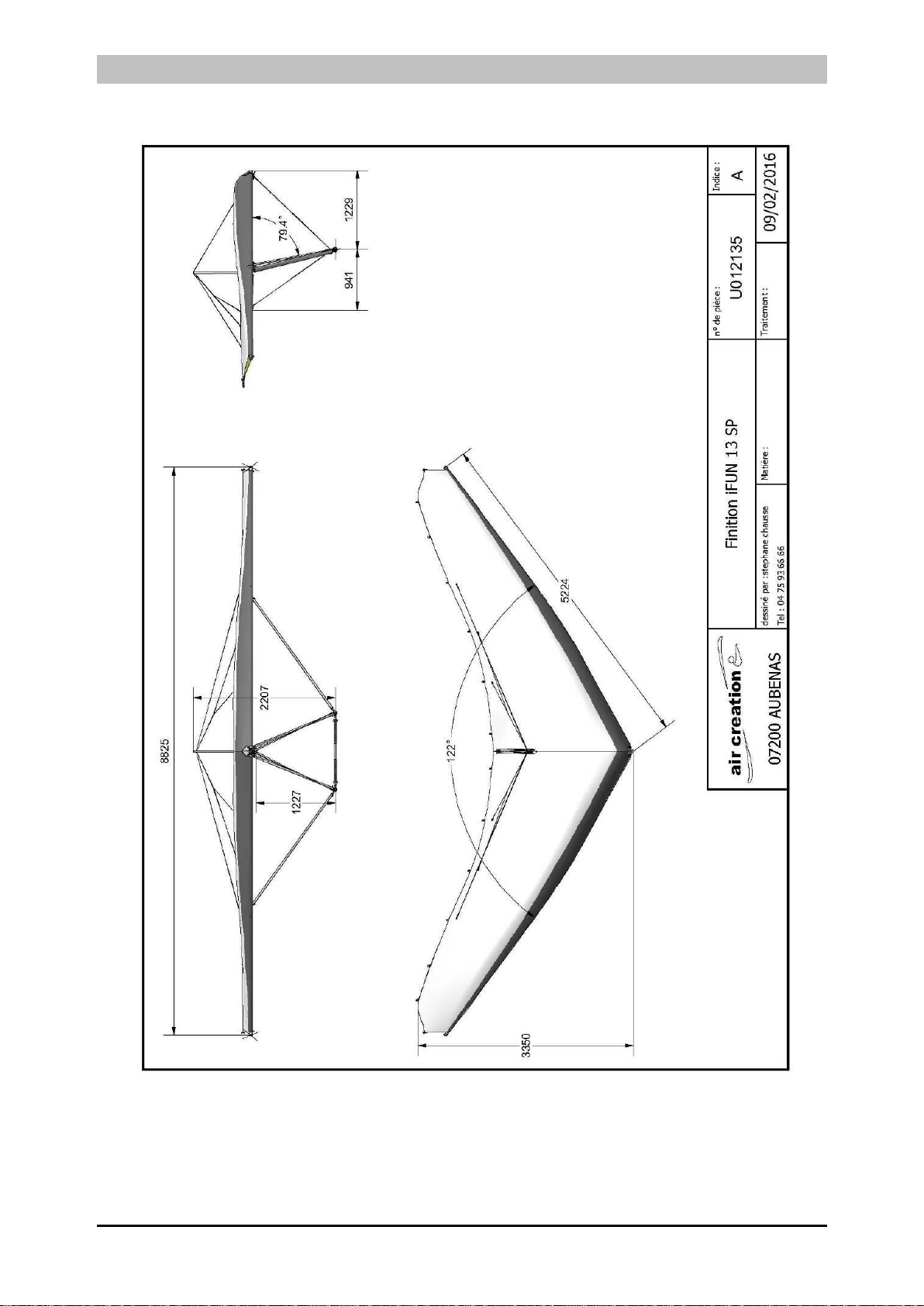
3.2 3-Perspective Diagram .................................................................................................5
Figure 3-1 : iFUN 13 SP in 3 Perspectives................................................................................5
4Technical Specifications - Performance.........................................................................6
4.1 Technical Specifications ...............................................................................................6
4.2 Maximum Load / Trikes Adaptation ..............................................................................6
4.3 Performance .................................................................................................................7
5Instructions for use...........................................................................................................8
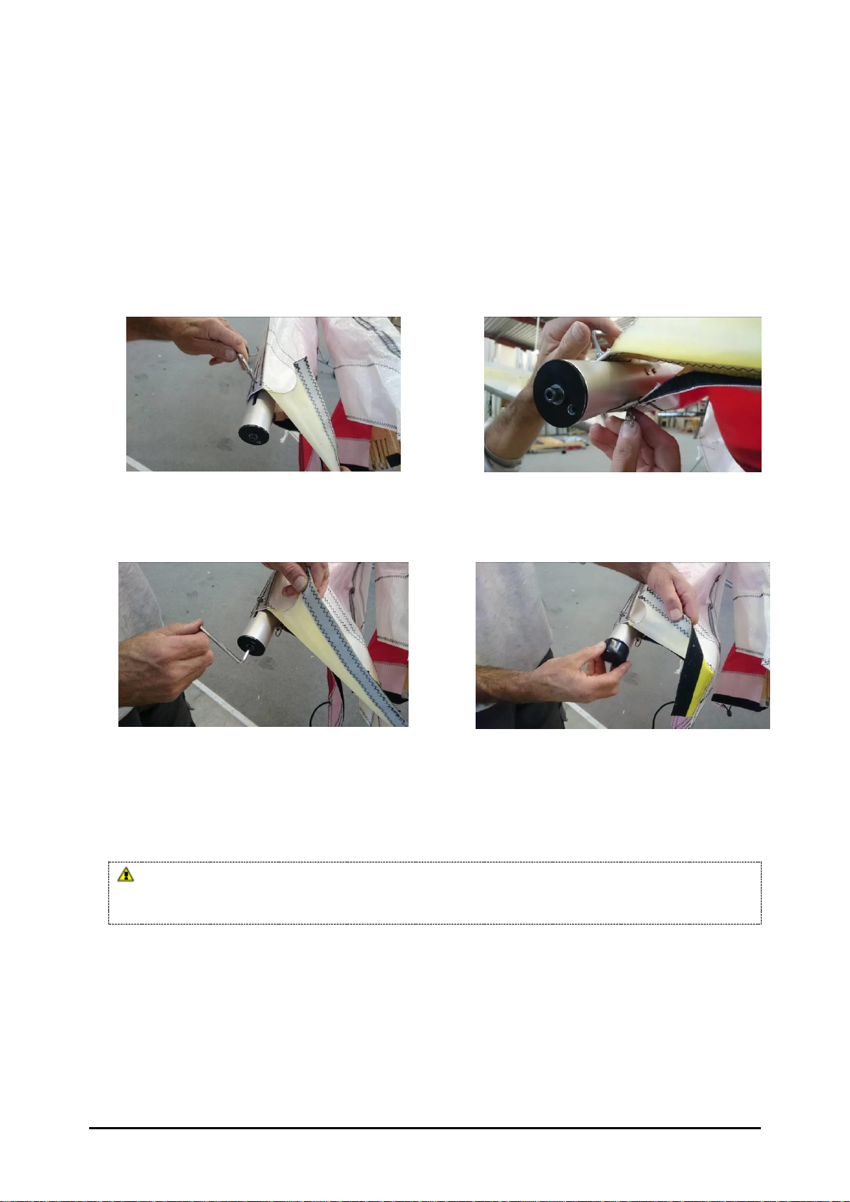
5.1 Assembly - Disassembly...............................................................................................8
5.1.1 Assembly................................................................................................................8
5.1.2 Disassembly.........................................................................................................12
5.2 Folding –Unfolding on the Pixel Trike........................................................................13
5.2.1 Folding on the Pixel Trike.....................................................................................13
5.2.2 Unfolding on the Pixel Trike .................................................................................16
5.3 Pre-Flight Check .........................................................................................................19
5.4 Flight Specifications....................................................................................................20
5.4.1 Operational Limitations.........................................................................................20
5.4.2 Controls................................................................................................................20
5.4.3 Flight Techniques.................................................................................................20
5.4.4 Adjustments..........................................................................................................24
6Maintenance.....................................................................................................................27
6.1 Transportation.............................................................................................................27
6.2 Storage........................................................................................................................27
6.3 Inspections & Scheduled Maintenance.......................................................................27
6.3.1 Time Limits............................................................................................................27
6.3.2 Safety Procedures..............................................................................................28
6.3.3 Wing Maintenance Schedule................................................................................29
6.4 Unscheduled Maintenance.......................................................................................30
6.4.1 General ................................................................................................................30
6.4.2 Inspection after Heavy Landing........................................................................30
6.4.3 Inspection after Heavy Turbulence...................................................................30
7Appendix ..........................................................................................................................31
7.1 Maintenance Operation Board....................................................................................31
7.2 Wing –Quality Form ...................................................................................................33

GDMANiFUN 13 SP-1G Version 0030 3
2 Amendment Record Sheet
2.1 Table of Amendments
Review
Date
Comment
Section
0030
09-2021
Reference document
2.2 Amendments
The information in this manual is based on the data that was available at the time of its
publication. The latest amendments to this manual will be issued on the Air Création
website (http://www.aircreation.fr) in PDF format. This should be printed out and added
to the manual. The amendment table should at that time be updated with the appropriate
details and date. Therefore it is important for operators to check the website regularly for
any amendments that have been made. If any errors or omissions are found in this manual
please advise the factory.

GDMANiFUN 13 SP-1G Version 0030 4
3 General
3.1 About this Document
This manual is a legal document which is approved for use with Air Creation iFun 13 SP
wing.
It must be used in conjunction with the particular trike’s operating handbook.
It must remain with the aircraft, and not be amended or altered without authority from Air
Creation.
All pilots should read this manual before flying as pilot in command of the aircraft to
which it refers.
This manual is not intended to teach you how to fly the aircraft. Learning to fly should be
accomplished under the supervision of a suitably qualified flight instructor experienced in
flying this type of aircraft.
What this manual will do is provide the information necessary to a qualified pilot for the
safe flight of this weight shift aircraft.

GDMANiFUN 13 SP-1G Version 0030 5
3.2 3-Perspective Diagram
Figure 3-1 : iFUN 13 SP in 3 Perspectives

GDMANiFUN 13 SP-1G Version 0030 6
4 Technical Specifications - Performance
4.1 Technical Specifications
Area
13 m² (140 sq ft)
Maximum wing loading
19,2 kg/m²
Airfoil type
Double surface 40%
Span
8,80 m (29 ft)
Nose angle
122°
Aspect ratio
6
Empty weight
35 kg (77 lbs)
Ultimate load factors
+ 6g - 3g
Maximum take-off weight
250 kg (551 lbs)
Limit load factors
+ 4g / 0g (-2g under gust)
4.2 Maximum Load / Trikes Adaptation
The following chart defines the useful load of our various trike models with the iFun 13 SP wing.
Trike Type
MTOW
Standard empty
load
Maximum empty
load
Maximum useful load *
Pixel 250
230 kg (507 lbs)
94 kg (207 lbs)
139 kg (306 lbs)
136 kg (300 lbs)
Pixel 303 XC
230 kg (507 lbs)
100 kg (221 lbs)
140,5 kg (310 lbs)
130 kg (287 lbs)
Pixel Aero 1000
230 kg (507 lbs)
114 kg (251 lbs)
141 kg (311 lbs)
116 kg (256 lbs)
* Optional equipment excluded
Other adaptations:
In the case of the adaptation of a trike from another factory or amateur built, different
from those specified above, the maximum total weight of the trike under must be less
than 215 kg (474 lbs).
Then progressive tests will be performed to check the adaptation wing/trike, especially
concerning the position of the control bar and the thrust line height.
Check during fitting whether the trike propeller stays clear of the lower rear
longitudinal cables and the keel. A minimum clearance of 10 cm (4 inches) should
be respected when the hang point is set to the front position and the wing is fully
nose up and all the way banked on one side.

GDMANiFUN 13 SP-1G Version 0030 7
4.3 Performance
The indicated speeds are CAS corrected speeds.
(*)The indicated performances were measured with the standard propellers fitted on the
trikes. The performances obtained with the optional propellers proposed are at least
equivalent.
Trike
Pixel 250
Pixel 303 XC
Pixel Aero 1000
Take-off
Weight
180 kg
Max 230 kg
180 kg
Max 230 kg
180 kg
Max 230 kg
397 lbs
507 lbs
397 lbs
507 lbs
397 lbs
507 lbs
Stall speed
41 km/h
44 km/h
41 km/h
44 km/h
41 km/h
44 km/h
25 mph
27 mph
25 mph
27 mph
25 mph
27 mph
Take-off run
40 m
55 m
40 m
53 m
40 m
55 m
131 ft
180 ft
131 ft
174 ft
131 ft
180 ft
50 ft clearing
distance
90 m
110 m
85 m
105 m
90 m
110 m
295 ft
361 ft
278 ft
344ft
295 ft
361 ft
Climb rate
4,2 m/s
2,6 m/s
4,5 m/s
2,8 m/s
4,3 m/s
2,7 m/s
827 ft/mn
512 ft/mn
886 ft/min
551 ft/min
847 ft/mn
532 ft/mn
Landing
distance from
50 ft height
135 m
145 m
135 m
145 m
135 m
145 m
442 ft
475 ft
442 ft
475 ft
442 ft
475 ft
Take-off and
landing Side
wind limits
25 km/h
15 mph
V.N.E. (velocity
never to
exceed)
120 km/h
74 mph
V.man (never
to be exceeded
in very
turbulent air)
88 km/h
54 mph

GDMANiFUN 13 SP-1G Version 0030 8
5 Instructions for use
5.1 Assembly - Disassembly
5.1.1 Assembly
In 3.8 m (for a wing folded in 5.3 meters, disregard the instructions for assembly of the rear parts of the
leading edges).
1. Open the wing bag, make sure that the A-frame is on top, remove fastenings and disengage the
rear part of the bag.
2. Take out the rear part of the leading edges, the battens and the tip struts of their bag.
3. Unfold each tip of the sail. Remove all Velcros. Remove foam guards (rear of keel, ends of A-
frame, hang block APR).
4. Assemble the control bar on the connector secured to the left A-frame strut by means of the 6 mm
CHC bolt, the two stainless steel washers, the two plastic washers, the wing nut and the safety ring
(Figure 5-1).
5. Assemble the right A-frame strut to the base of the control bar using the push-pin, no cable must
pass inside.
6. Remove the foam guards at the end of the front part of the leading edges (Figure 5-2). Store the
Velcros and the guards in the wing bag.
7. Slide the rear parts of the leading edge into the sail and into the front part. Observe the right / left
indications on the tubes. (Figure 5-3)
The two rear parts of the leading edges are not identical. A sticker on the tube indicates whether it is a
right (D) or left (G). An inversion can have serious consequences because it modifies the tip struts angle
resulting in negative twisting of the tips and strong longitudinal instability.
Figure 5-1
Figure 5-2
Figure 5-3
Figure 5-4

GDMANiFUN 13 SP-1G Version 0030 9
8. Finish to engage the rear parts of the leading edges in the front part by rotating them to line up the
tubes slots and the horizontal bolt connecting the crossbar on the front part of the leading edge.
Push them forward as far as possible. Make sure that the plastic lugs and the openings for the tip
struts at the rear of the tubes are face-to-face Once installed the rear leading edge slot should be
located on the channel horizontal bolt. It should be impossible to rotate the leading edge, if
correctly assembled.
9. Remove the plastic caps from the wingtip sleeves. Pull the sail tightly backwards and position the
leading edge fabric of each half-wing outward.
10. Install the fastening screw of the sail at each end of the wing using the Allen key placed in the
plate close to the head of the screw, on the Right side (Figure 5-4). Insert the screws first through
the extrados grommets, then into the drilling of the tensioning bracket and finally into the lower
surface grommet (Figure 5-5). A stainless steel washer should be placed under the head of the
screw and a second between the intrados eye and the butterfly nut.
Figure 5-5
Figure 5-6
11. Tighten the sail on each leading edge by tightening the screw at the sleeve end of 20 turns using
the Allen wrench. Replace the plastic caps at the end of the leading edges (Figures 5-7 & 5-8).
Figure 5-7
Figure 5-8
12. Straighten the A-frame by engaging the swan catch of the front longitudinal lower cables on the
rail screw at the wing nose without locking the lever.
13. Assemble the 2 lateral struts on the shroud base connecting with the crossbars. Position the struts
vertically by pushing them with the shoulder to facilitate the installation of the screw. The leading
edge of the struts profile must be directed outwards. The screws must be installed with a stainless
washer and a plastic washer on each side of the tube. Secure with the split ring.
The upper shroud bases must be pivoted in such a way that their connecting screw with the Shroud/crossbar
axis is directed with the head on the leading edge side and the nut on the trailing edge side. Otherwise, the
leading edge tube will be damaged by the nut when folding the wing. (Figure 5-9).
14. Assemble the 2 lateral struts on the bases of the control bar by means of the screws, with a
stainless steel washer and a plastic washer on each side of the tube. Secure with the split ring
(Figure 5-10).

GDMANiFUN 13 SP-1G Version 0030 10
Figure 5-9
Figure 5-10
15. Lift the nose of the wing and tilt it to rest on its A-frame. Remove and store the bag (Figure 5-11).
16. Push the swan catch lever of the front lower longitudinal cables into the nose rail and lock it with
the push-pin and safety washer.
17. Open the 2 half-wings to the maximum (Figure 5-12).
Figure 5-11
Figure 5-12
18. Pull the tensioning lever of the crossbars back from the kingpost foot, taking care not to cross the
cables.
19. Insert the nylon head at the top of the kingpost, then the kingpost on the base attached to the top of
the keel, between the two tensioning cables (Figure 5-13).
20. Make sure that the struts to crossbars link parts do not block in the openings on the undersurface
of the sail and then pull the tensioning lever back towards the trailing edge to hook it onto the
screw of the rail at the end of the keel. (Figure 5-14).
Figure 5-13
Figure 5-14
21. Tilt the wing on its nose.
22. Carefully slide the sail bent battens in their respective pockets and tension the sail by fastening the
Easyfit tighteners (Battens with red end caps on the Left side and those with Gray-colored ends on
the Right side).
23. Lower the swan catch lever of the crossbars tensioning cables and lock it into the rail using the
push-pin.

GDMANiFUN 13 SP-1G Version 0030 11
24. Install the tip struts in the appropriate openings on the leading edge. Insert them all the way into
their housings and rotate them until they block. Check that they are correctly blocked by pulling
them towards the rear. Raise the sail and open the undersurface to upper surface Velcros for ease
of access. (Figure 5-15).
25. Place the two straight battens of the wing tips on the plastic lug attached to the tube of the leading
edge, and tighten the upper surface with the clasps. (Red end to left side, gray end to right side)
(Figure 5-16).
Figure 5-15
Figure 5-16
26. Fit the tensioning bungees of the undersurface twice over the easyfit tensioner of the wing tip
batten and close the Velcros between intrados / extrados (Figure 5-17).
27. Close the fabric closures at the tips by means of their velcros.
28. Close the inspection hatches of the leading edges / crossbars links in the undersurface by mean of
the zippers.
29. Store foam guards and Velcros in the bag. Keep a small Velcro apart to wrap it later around the
front tube of the trike to lock the control bar on it.
30. When assembling the wing on the Pixel trike, slide the safety cable through the strap near the
kingpost foot, make a lap behind the kingpost, slide it back into the buckle, and then fasten it to
the trike's upper beam. The safety cable must pass under the tensioning cables. This operation
secure both the attachment of the tricycle and the crossbars tensioning system. (Figure 5-18)
Figure 5-17
Figure 5-18
31. Before lifting the wing's nose, slide the upper beam foam headrest upward to protect the upper
beam from contact with the rear longitudinal lower cables attachment under the keel.
A careful and complete pre-flight check as described in the flight manual is mandatory
after wing assembly. Pay special attention to potential transport damage. Carefully inspect all
fasteners, cables, proper placement of lateral struts and their fixing screws and nuts, the shape of the
leading edge Mylar and the overall symmetry of the wing before flying.

GDMANiFUN 13 SP-1G Version 0030 12
5.1.2 Disassembly
The disassembly of the wing is carried out by the inverse operations of the assembly,
following the reverse order of the instructions.
Begin by removing the tip struts and the last straight battens before untightening the
crossbars tensioning cables.
Before fully folding the two half-wings, dismount the kingpost and slide the tensioning
lever as far as possible ahead of the kingpost foot so that it can not catch in one of the
openings of the sail.
Do not forget to place the foam guards provided for the hang point block APR, the rear
tip of the keel and the lower joints of the A-frame before closing the bag.
Never attempt to put the wing flat on the ground without first disassembling the lateral
struts. The connecting parts of the struts would be definitively damagded! If this is done by
mistake, a complete disassembly of the struts and of all their connecting parts with the
control bar and the leading edges is essential for inspection and replacement.

GDMANiFUN 13 SP-1G Version 0030 13
5.2 Folding –Unfolding on the Pixel Trike
5.2.1 Folding on the Pixel Trike
Folding should only be carried out after the engine block and exhaust have completely cooled down.
The sail could be irreparably damaged by contact with a hot part of the engine and its accessories.
1. Place the trike facing the wind.
2. Remove the windscreen, the locking screw of the upper beam on the engine mount and the fixing
screw of the front tube on the lower beam.
3. Remove the ignition key, swing the instrument panel backwards and apply the parking brake.
4. Lift the control bar (one hand on the bar and the other on the front tube of the trike) to clear the
front tube from the lower beam. Press the top of the brake pedal with the foot to prevent the tricycle
from moving backward and tipping over. Lower the wing until the intermediate support of the front
tube is fitted to the end of the lower beam. Replace the fixing screw of the support on the beam
with its wing nut and its split safety ring (Figures 5-19 & 5-20). Reset the parking brake.
Figure 5-19
Figure 5-20
5. Block the control bar against the front tube, horizontal wing, using one of the small velcros used to
join the battens when the wing is folded.
6. Remove the hang point safety cable from the webbing of the central crossbars protection and from
the kingpost. Fix it again directly to the upper beam of the trike.
7. Remove the struts at the tips of the wings by turning them on themselves and pulling.
8. Remove the last straight battens at the tips.
9. Raise the crossbars cables tensioning lever at the end of the keel, releasing the push-pin. Replace
the push-pin on the rail.
10. Carefully slide all the uppersurface battens out of their pockets, after unlocking the "Easyfit"
tensioners, starting with those in the center.
11. Disengage the crossbars cables tensioning lever from the rail at the end of the keel and allow the
leading edges to close naturally (Figure 5-21).
12. Clear the kingpost from the lug fixed to the top of the keel, between the two tensioning cables.
Place one foot on one of the landing gear legs to facilitate operation, if necessary. Position the
kingpost on the sail with its lower end facing forward.
13. Slide the crossbars cables tensioning lever forward of the kingpost foot, then under the sail so that
it can not catch in one of the openings of the sail.
14. Place the propeller in a horizontal position.
15. Close the two leading edges against each other by simultaneously pulling the center trailing edge of
each half wing and then the wing tips (Figure 5-22).

GDMANiFUN 13 SP-1G Version 0030 14
Figure 5-21
Figure 5-22
16. Slide the sailcloth over the leading edges along their entire length, pulling them outward as far as
possible.
For folding in 5.3 meters:
1. Roll the sailcloth parallel to the keel and attach it with Velcros (a large Velcro between the
hanging block APR and the attachment of the lower longitudinal cables, a large Velcro behind
the struts attachment, a small Velcro on each half-wing towards their rear end).
2. Collect the battens, the kingpost and the tips struts, attach them by a small Velcro, store them
in their bag and slip them over the sail under one of the Velcros.
3. Place the foam guards over the hang point block and at the end of the keel, then the wing cover
and close the zipper from the rear end to the struts attachment.

GDMANiFUN 13 SP-1G Version 0030 15
For folding in 3.8 meters:
1. Roll the sailcloth parallel to the keel in front of the struts attachment, and attach it with Velcros (a
large Velcro between the hanging block APR and the attachment of the lower longitudinal cables and
a large Velcrojust behind the struts attachment).
2. Remove the plastic caps at the end of the leading edges and slacken the screw at the end of the sleeve
to the maximum (20 turns) (Figures 5-7 & 5-8). Use the Allen wrench in the plate close to the screw
head, right side (Figure 5-4).
3. Remove the fastening screw of the sail at each wing tip (Figure 5-5) and replace it on the sleeve with
the wing nut and split ring after the sail is released.
4. Replace the Allen wrench in its housing and the plastic caps at the end of the leading edge sleeves.
5. Slide the rear parts of the leading edges out of the front parts and out of the sail while pulling
backwards (Figure 5-25).
6. Open the undersurface to uppersurface Velcros and the fabric closures at the tips.
7. Place the foam guards on the end of the front parts of the leading edges of the leading edges (Figure
5-23).
Figure 5-23
Figure 5-24

GDMANiFUN 13 SP-1G Version 0030 16
8. Roll each end of the sail at the tips parallel to the leading edge and attach them separately with a
small Velcro.
9. Fold over each end of the sail on the front of the wing, taking care not to cause a sharp angle in the
mylar of the leading edges. Pull the tips towards the nose of the wing. Attach the whole fabric with
the Velcros (Figure 5-24).
10. Slide rear parts of leading edges, kingpost, battens and tip struts into the provided bag. Position the
cover forward, over the wing, under one of the Velcros, the widest part facing backwards.
11. Place the foam guards over the hang point block and at the end of the keel, then the"Short Pack" bag
on the wing by threading it from the back. Close the zippers.
5.2.2 Unfolding on the Pixel Trike
1. Place the trike facing the wind.
2. Engage the parking brake and lock the control bar against the front tube with a small Velcro.
3. Open the zippers of the bag and disengage it from the wing.
For a wing folded in 5.3 meters, continue the procedure by proceeding directly to instruction
No. 14 under asterisk *
4. Remove the rear parts of the leading edges, the kingpost, the battens and the tip struts from their bag.
5. Unfold each end of the sail. Remove all Velcros.
6. Remove the guards at the end of the front part of the leading edges. Store covers, Velcros and
protectors.
7. Slide the rear parts of the leading edge into the sail and into the front part (Figure 5-25). Observe the
right / left indications on the tubes. (Figure 5-3)
The two rear parts of the leading edges are not identical. An sticker on the tube indicates whether it
is a right (D) or left (G). An inversion can have serious consequences because it modifies the tip struts
angle resulting in negative twisting of the tips and strong longitudinal instability.
8. Finish to engage the rear parts of the leading edges in the front part by rotating them to line up the
tubes slots and the horizontal bolt connecting the crossbar on the front part of the leading edge. Push
them forward as far as possible. Make sure that the plastic lugs and the openings for the tip struts at the
rear of the tubes are face-to-face Once installed the rear leading edge slot should be located on the
channel horizontal bolt. It should be impossible to rotate the leading edge, if correctly assembled.
(Figure 5-26).
Figure 5-25
Figure 5-26

GDMANiFUN 13 SP-1G Version 0030 17
9. Remove the plastic caps from the wingtip sleeves. Pull the sail tightly backwards and position the
leading edge fabric of each half-wing outward.
10. Install the fastening screw of the sail at each end of the wing using the Allen key placed in the plate
close to the head of the screw, on the Right side (Figure 5-4). Insert the screws first through the
extrados grommets, then into the drilling of the tensioning bracket and finally into the lower surface
grommet. A stainless steel washer should be placed under the head of the screw and a second between
the intrados eye and the butterfly nut. Secure with the split ring. (Figure 5-5 & 5-6).
11. Tighten the sail on each leading edge by tightening the screw at the sleeve end of 20 turns (Figure 5-7).
Use the Allen wrench fitted in the plate next to the screw on the Right side sleeve (Figure 5-4).
Replace the plastic caps at the end of the leading edges (Figures 5-8).
*Wing folded in 5.3 meters
12. Release the pitch lines of any retaining elements and position them on the top of the sail.
13. Swing the instrument panel backwards.
14. Place the propeller in a horizontal position.
15. Sit on the tricycle, open the two half-wings symmetrically, using the struts, until the point of
equilibrium is reached where the opening remains stable (Figures 5-27 & 5- 28).
Figure 5-27
Figure 5-28
16. Finish opening each half-wing by pulling alternately on the struts or on the rear ends of the leading
edges.
17. Pull the crossbars tensioning cables behind the kingpost foot on the upper surface and fit the kingpost
over the lug on the top of the keel between the two tensioning cables, taking care not to tangle the
cables (Figure 5-13). Put one foot on one of the landing gear legs to facilitate the operation, if
necessary.
18.Make sure that the struts to crossbars link parts do not block in the openings on the undersurface of the
sail and then pull the tensioning lever back towards the trailing edge to hook it onto the screw of the rail
at the end of the keel. (Figure 5-29)
Figure 5-29
Figure 5-30

GDMANiFUN 13 SP-1G Version 0030 18
19. Carefully slide the sail bent battens in their respective pockets and tension the sail by fastening the
Easyfit tighteners (Battens with red end caps on the Left side and those with Black-colored ends on
the Right side).
20. Lower the swan catch lever of the crossbars tensioning cables and lock it into the rail using the push-
pin. (Figure 5-30).
21. Place the two straight battens of the wing tips on the plastic lug attached to the tube of the leading
edge, and tighten the upper surface with the easyfit clasps. (Red end to left side, black end to right
side) (Figure 5-16).
22. Install the tip struts in the appropriate openings on the leading edge. Insert them all the way into their
housings and rotate them until they block. Check that they are correctly blocked by pulling them
towards the rear. Raise the sail and open the undersurface to upper surface Velcros for ease of access.
(Figure 5-15 & 5-16)
23. Fit the tensioning bungees of the undersurface twice over the easyfit tensioner of the wing tip batten
and close the Velcros between intrados / extrados (Figure 5-17).
24. Close the fabric closures at the tips by means of their velcros.
25. Slide the safety cable through the strap near the kingpost foot, make a lap behind the kingpost, slide it
back into the buckle, and then fasten it to the trike's upper beam. The safety cable must pass under the
tensioning cables (Figure 5-18). This operation secure both the attachment of the tricycle and the
crossbars tensioning system.
26. Tilt the instrument panel backwards, remove the fixing screw from the intermediate support of the
front tube onto the lower beam. Lift the control bar (one hand on the bar and the other on the front
tube of the trike) to clear the front tube intermediate support from the lower beam. Press the top of the
brake pedal with the foot to prevent the tricycle from moving backward and tipping over. Lift the
wing until the end of the front tube is fitted to the end of the lower beam.
27. Replace the locking screw of the upper beam on the engine mount and the fixing screw of the front
tube on the lower beam with their wing nuts and its split safety rings.
28. Tilt the instrumentation console forward, fit the windscreen, and remove the Velcro blocking the
control bar on the front tube.
29. Store foam guards and Velcros in the bag. Keep a small Velcro apart to wrap it around the front tube
of the trike to lock the control bar on it.
A careful and complete pre-flight check as described in the flight manual is
mandatory after wing assembly. Pay special attention to potential transport damage.
Carefully inspect all fasteners, cables, proper placement of lateral struts and their fixing
screws and nuts, the shape of the leading edge Mylar and the overall symmetry of the wing
before flying.

GDMANiFUN 13 SP-1G Version 0030 19
5.3 Pre-Flight Check
A pre-flight check of the wing is essential. Instructions for the pre-flight check of the trike can be
found in the user manual of the trike.
1. Check the camber of the two leading edges.
2. Check the thimbles of the front lower longitudinal cables and the correct fastening of the
tensioning device and the push-pin. Slide your hand along the leading edges to check for possible
defects.
3. Check the cross-bar/leading edges link by unzipping the lower surface access. Check that the
fastening of the lateral struts is correct and the sail is not snagged on a metal part. Check the
positioning and tightening of screws, washers, nuts, butterflies and split rings.Close the lower
surface access.
4. Check the fastening of the sail at the wing tips, as well as the blockage positioning of the two
rotating sleeves by means of the Parker screw and the correct positioning of the tip struts. (Check
by pulling the tip struts towards the rear.)
5. Check whether the battens are securely positioned and the closure of the tensioners on the trailing
edge.
6. Check the condition of the pitch lines and their fastening to the sail.
7. Check whether any of the upper cables is circled around the king post and that the pitch lines are
well placed in the grooves of the king post pulleys.
8. Check the axes of the swiveling piece, its safety pins and the thimbles and Nicopress of the rear
lower cables at the keel end.
9. Slide your hand along all the lower cables and struts to detect signs of wear.
10. Check the proper passage of the tensioning cables on each side of the king post. Inspect the
tensioning system at the end of the keel, the nuts and bolts, and the position of the push-pin and its
safety washer.
11. Check the fastening of the lateral struts of the A frame. Check the nuts, bolts, washers and safety
rings, the position of the push-pin and its safety washer.
12. Check the condition of the thimbles and Nicropress of the longitudinal lowers cables. All of the
cables should be free to pivot in the direction of tension forces.
13. Check the assembly of the crossbar central junctions, the nuts and bolts, the protection, the
retaining straps on the keel, and the fastening of the tensioning cables.
14. Check the condition (possible twists, cracks) and the free movement of the hang point bracket.
15. Check that all zippers on the inspection hatches are closed and that the under / upper surfaces and
wingtip closure are correctly positioned with their velcros.

GDMANiFUN 13 SP-1G Version 0030 20
5.4 Flight Specifications
5.4.1 Operational Limitations
Warning:
This wing is not designed for aerobatics.
It is imperative to respect the flight envelope!
Maximum Pitch attitudes 30° nose up, 30° nose down
Maximum Bank angle 60°
Aerobatics and deliberate spinning prohibited
V.N.E. (never to be exceeded): 75 mph (120 km/h)
Maximum Take-Off Weight : 250 kg (551 lbs)with compatible Trike
230 kg (507 lbs)with Pixel Trike
Acceleration limits +4/-0g ; positive “g” at all times
Stalls authorized only in glide path with a progressive speed reduction
and throttle to idle position.
The instructions in paragraph 5.3.3 concerning stall exercises must be
followed.
Over these limits, stability problems, structural failure or irreversible “tumbling”
motions may occur.
5.4.2 Controls
Control bar :
Pushing the control bar forward causes the wing to pitch its nose up, which increases the
angle of attack (causing the aircraft to climb) –primary effect, and a decrease in air speed
–secondary effect.
Roll control is effected from lateral movement of the control frame, and follows weight
shift convention, i.e. bar right, aircraft rolls to the left.
A separate yaw control is not provided. Like other weight shift aircraft, yaw is provided
from the secondary effect of banking.
5.4.3 Flight Techniques
Taxiing :
Avoid turning sharply as this generates large amounts of torque and hence wear,
transmitted to the pylon, hang point and keel. Always try to keep the wing aligned with
the trike when turning by bracing the control bar. Turning circle is very small, but
beware –wing tips stick out and can move around their arc very fast!
Take-off and landing techniques:
Take-off is conventional. Keep the aircraft straight using the nose wheel steering. Allow
the bar to float in the neutral position in pitch and keep the wings level. Let the control
Table of contents
Other Air Creation Aircraft manuals

Air Creation
Air Creation BioniX 15 Owner's manual

Air Creation
Air Creation XP 12 Manual

Air Creation
Air Creation Skypper 582 S User manual

Air Creation
Air Creation GTE Trek 503 Instructions for use

Air Creation
Air Creation FUN 450 Manual

Air Creation
Air Creation iFun 13 Owner's manual

Air Creation
Air Creation iFUN 16 Manual

Air Creation
Air Creation iFun XL Owner's manual

Air Creation
Air Creation FUN 14 Manual

Air Creation
Air Creation iFun 16 SP Manual