Air Creation iFun 13 Owner's manual

GDMUiF13-1G Version 0030 2
1 Table of Contents
1Table of Contents................................................................... 2
2Amendment Record Sheet..................................................... 4
2.1 Table of Amendments.......................................................................... 4
2.2 Amendments........................................................................................ 4
3General ................................................................................... 5
3.1 About this Document............................................................................ 5
3.2 3-Perspective Diagram......................................................................... 6
Figure 3-1: iFun 13 in 3 Perspectives.......................................................................................6
4Technical Specifications –Performance.............................. 7
4.1 Technical Specifications....................................................................... 7
4.2 Maximum Added Load / Trikes Adjustment ......................................... 7
4.3 Performance (*).................................................................................... 8
5Instructions for Use ............................................................... 9
5.1 Rigging................................................................................................. 9
5.1.1 Assembly................................................................................................................9
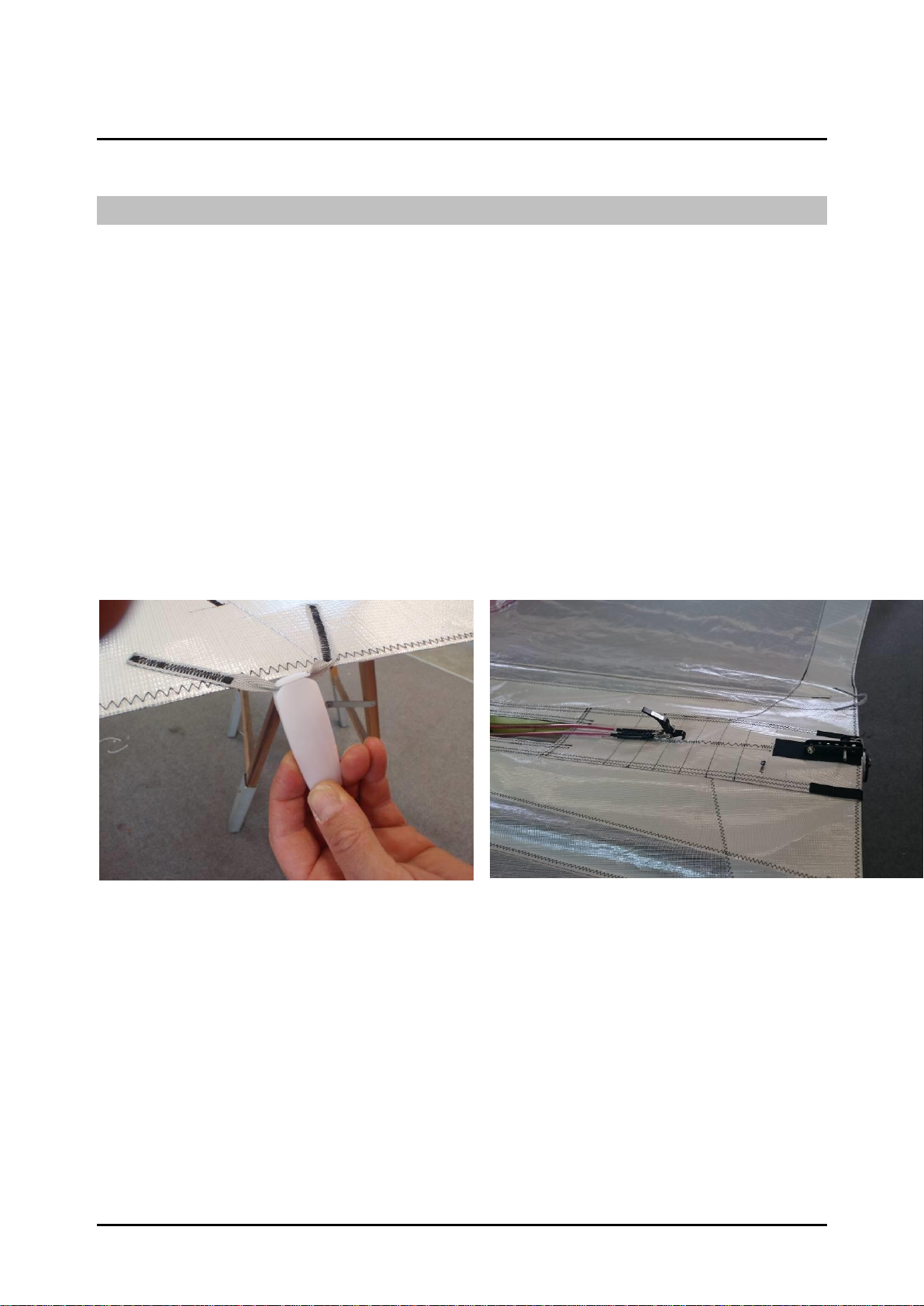
Figure 5-1 : EasyFit Tighteners..................................................................................................9
Figure 5-2 : Path of Tensioning Cables .....................................................................................9
5.1.2 Disassembly.........................................................................................................10
5.2 Preflight Check................................................................................... 11
5.3 Flight Specifications........................................................................... 12
5.3.1 Operational Limitations.........................................................................................12
5.3.2 Controls ................................................................................................................12
5.3.3 Flight Techniques .................................................................................................12
6Maintenance ......................................................................... 20
6.1 Assembling from Shipping Crate........................................................ 20
6.1.1 Reassembly Guide .............................................................................................20

GDMUiF13-1G Version 0030 3
Figure 6-1 21
Figure 6-2 21
Figure 6-3 21
Figure 6-4 21
Figure 6-5 21
6.2 Transportation.................................................................................. 22
6.3 Storage.............................................................................................. 22
6.4 Inspections & Scheduled Maintenance.......................................... 22
6.4.1 Time Limits...........................................................................................................22
6.4.2 Safety Procedures..............................................................................................23
6.4.3 Wing Maintenance Schedule................................................................................24
6.5 Unscheduled Maintenance................................................................. 25
6.5.1 General.................................................................................................................25
6.5.2 Inspection after Heavy Landing............................................................................25
6.5.3 Inspection after Heavy Turbulence.......................................................................25
6.6 Maintenance Operation Board........................................................ 26
6.7 Notes................................................................................................. 28
6.8 Wing –Quality Form .......................................................................... 29

GDMUiF13-1G Version 0030 4
2 Amendment Record Sheet
2.1 Table of Amendments
Review
Date
Comment
Section
0030
09-2021
Reference document
2.2 Amendments
The information in this manual is based on the data that was available at the time of its
publication. The latest amendments to this manual will be issued on the Air Création
website (http://www.aircreation.fr) in PDF format. This should be printed out and added
to the manual. The amendment table should at that time be updated with the appropriate
details and date. Therefore it is important for operators to check the website regularly for
any amendments that have been made. If any errors or omissions are found in this manual
please advise the factory.

GDMUiF13-1G Version 0030 5
3 General
3.1 About this Document
This manual is a legal document which is approved for use with Air Creation iFun 13
wing.
It must be used in conjunction with the particular trike’s operating handbook.
It must remain with the aircraft, and not be amended or altered without authority from Air
Creation.
All pilots should read this manual before flying as pilot in command of the aircraft to
which it refers.
This manual is not intended to teach you how to fly the aircraft. Learning to fly should be
accomplished under the supervision of a suitably qualified flight instructor experienced in
flying this type of aircraft.
What this manual will do is provide the information necessary to a qualified pilot for the
safe flight of this weight shift aircraft.

GDMUiF13-1G Version 0030 6
3.2 3-Perspective Diagram
Figure 3-1: iFun 13 in 3 Perspectives

GDMUiF13-1G Version 0030 7
4 Technical Specifications –Performance
4.1 Technical Specifications
Area
13 sq m (140 sq ft)
Maximum wing loading
19.2 kg/sq.m (3.9 lbs/sq.ft)
Airfoil type
Double surface 40%
Span
8.8 m (29 ft)
Nose angle
122°
Aspect ratio
6
Empty weight
31 kg (68 lbs)
Ultimate load factors
+ 6g - 3g
Maximum take-off weight
250 kg (551 lbs)
Limit load factors
+ 4g 0g (-2g under gust)
4.2 Maximum Added Load / Trikes Adjustment
The following chart defines the useful load of our various trike models with the iFun 13 wing.
Trike Type
MTOW
Standard empty
load
Maximum empty
load
Maximum useful load *
Pixel 250
230 kg (507 lbs)
90 kg (198 lbs)
139 kg (306 lbs)
140 kg (309 lbs)
Pixel 303 XC
230 kg (507 lbs)
96 kg (212 lbs)
140,5 kg (310 lbs)
134 kg (295 lbs)
Pixel Aero 1000
230 kg (507 lbs)
110 kg (242 lbs)
141 kg (311 lbs)
120 kg (265 lbs)
* Optional equipment excluded
Other adaptations:
In the case of the adaptation of a trike from another factory or amateur different from
those specified above, the maximum total weight of the trike under must be less than 219
kg (483 lbs).
Then progressive tests will be performed to check the adaptation wing/trike, especially
concerning the position of the control bar and the thrust line height.
Check during fitting whether the trike propeller stays clear of the lower rear
longitudinal cables and the keel. A minimum clearance of 10 cm (4 inches) should
be respected when the hang point is set to the front position and the wing is fully
nose up and all the way banked on one side.

GDMUiF13-1G Version 0030 8
4.3 Performance (*)
The indicated speeds are CAS corrected speeds.
(*) The indicated performances were measured with the standard propellers that equip
the trikes. The performances obtained with the optional propellers proposed are at least
equivalent.
Trike
Pixel 250
Pixel 303 XC
Pixel Aero 1000
Take-off
Weight
180 kg
Max 230 kg
180 kg
Max 230 kg
180 kg
Max 230 kg
397 lbs
507 lbs
397 lbs
507 lbs
397 lbs
507 lbs
Stall speed
41 km/h
44 km/h
41 km/h
44 km/h
41 km/h
44 km/h
25 mph
27 mph
25 mph
27 mph
25 mph
27 mph
Take-off run
40 m
55 m
40 m
53 m
40 m
55 m
131 ft
180 ft
131 ft
174 ft
131 ft
180 ft
50 ft clearing
distance
90 m
110 m
85 m
105 m
90 m
110 m
295 ft
361 ft
278 ft
344ft
295 ft
361 ft
Climb rate
4,2 m/s
2,6 m/s
4,5 m/s
2,8 m/s
4,3 m/s
2,7 m/s
827 ft/mn
512 ft/mn
886 ft/min
551 ft/min
847 ft/mn
532 ft/mn
Landing
distance from
50 ft height
135 m
145 m
135 m
145 m
135 m
145 m
442 ft
475 ft
442 ft
475 ft
442 ft
475 ft
Take-off and
landing Side
wind limits
25 km/h
15 mph
V.N.E. (velocity
never to
exceed)
120 km/h
74 mph
V.man (never
to be exceeded
in very
turbulent air)
88 km/h
54 mph

GDMUiF13-1G Version 0030 9
5 Instructions for Use
5.1 Rigging
5.1.1 Assembly
1. Open the wing bag, make sure that the A-frame is on top, and remove fastenings and paddings.
2. Assemble the A-frame with the push-pin. Cables must not pass through the inside.
3. Lift the wing from the front and rotate it so that the wing is laying with the assembled control
frame flat on the ground. Carefully open the two half wings to their maximum extent.
4. Slip the tensioning handle behind the foot of the kingpost by the opening in the upper surface
taking care not to cross or twist the cables. (Figure 5-2).
5. Fit the king post plastic head at the top of the kingpost without entangling pitch lines.
6. Fit the king post onto its locating lug on the keel, between the two tensioning cables.
7. Carefully slide the upper sail bent battens in their respective pockets and tension the sail by
fastening the Easyfit tighteners (Figure 5-1).
Figure 5-1 : EasyFit Tighteners
Figure 5-2 : Path of Tensioning Cables
8. Pull the cross tube swan catch tensioner towards the trailing edge, then hook it to the rail screw at
the keel tip (Figure 5-2). To ease the operation, carefully center the A-frame, ensure that the tabs
and heat shrink coverings of the lower lateral cables do not get stuck in the sail opening at the
cross tube/leading edge connection and that the stainless steel tabs line up with the control bar.
9. Pull down the swan catch tension lever and fix it in the rail with the pushpin.
10. Raise the nose of the wing and lift it on its A-frame. To avoid dragging the tips of the wing on the
ground, it is recommended that a second person hold the back of the keel.
11. Fix the front lower longitudinal cables in the rail under the nose plate with the help of the swan
catch tension lever and the pushpin.
12. Install the tip struts in the appropriate openings on the leading edge. Insert them all the way into
their housings and rotate them until they block. Check that they are correctly blocked by pulling
them towards the rear. Raise the sail for ease of access.

GDMUiF13-1G Version 0030 10
13. Place the two straight battens of the wing tips on the plastic lug attached to the tube of the leading
edge, and tighten the upper surface with the clasps. Attach the undersurface bungees by pulling
them over the clasps.
14. Close the fabric closures at the tips by means of their velcros.
15. When connecting the trike, slip the security fastening cable through the loop in the security strap
aligned with the front of the kingpost, behind the kingpost, through the loop again, and then fix it
to the beam of the trike. The security cable should pass under the tensioning cables. This operation
secures the trike as well as fastening the crossbar tensioning system.
For the final stage of lifting the wing on the trike, follow the instructions in the trike
operating handbook.
5.1.2 Disassembly
Dismantling is carried out in reverse order of the assembling operations.
Before setting the wing flat on the ground, insert the protective padding on the
keel over the hang point bracket.
Before folding up the two half-wings,check that the handle of the tensionning
cables does not catch in the opening of the upper surface, disengage the kingpost, slide
the handle as far as possible in front of the kingpost foot so that it cannot catch an
element of sail or frame when closing the leading edges.
Never release the tension of the wing without first removing the straight battens of
the wing tips which rest on the leading edges.

GDMUiF13-1G Version 0030 11
5.2 Preflight Check
The wing preflight check will be easier if made before lifting the wing above the trike. The
following is a brief summary of the minimum pre-flight inspection, which assumes that the
scheduled maintenance checks outlined in the maintenance manual has been performed. If you
are unsure, it does no harm to increase the number of items in your inspection in accordance with
the recommendations of the maintenance manual.
1. Position the wing horizontally once coupled with the trike.
2. Visually check the symmetry of the two leading edges.
3. Check noses plates’ assembly, bolts, nuts, thimbles and Nicopress of the front lower longitudinal
cables, swan catch correctly positioned, pushpin and wires attached.
4. Slide your hand along the leading edges to check for possible damage. Make sure the profile of the
upper surface of the leading edge is free of deposits of raindrops, insects, snow or ice. Clean/dry if
necessary.
5. Check the crossbar/leading edges connection, bolts, nuts, by unzipping the lower surface access.
Check for correct fastening of lower flying wires and upper landing wires, also their condition, swages
and thimbles. Check that the sail is not snagged on a metallic part. Close the lower surface access.
6. Check the fastening of the sail at the wing tips and the position lock of the two pivoting sleeves by
means of the Parker screws.
7. Check the fitting of the upper surface battens and the closure of their tighteners on the trailing edge.
8. Check fitting and condition of the reflex bridles and their attachment to the sail.
9. Check that no upper cables are wrapped around the kingpost and that the luff lines are well positioned
in the grooves of the pulleys at the top of the kingpost.
10. Check the axes of the swiveling piece, its safety pins and the thimbles and Nicopress of the rear lower
cables at the keel end.
11. Check the correct routing of the tensioning cables on each side of the king post. Check the tensioning
system at the end of the keel, the nuts and bolts, the correct position and security of the push pin and
its safety washer.
12. Slide your hand along all of the lower cables to detect signs of wear.
13. Check that the lower cables are attached to the A frame, check the nuts and bolts, check the condition
of the cables and their Nicopress clamps, and the push-pin of the control bar. All the cables should be
loose enough to pivot in the direction of the tension. Close the leather cover webbings.
14. Check the assembly of the crossbar central junctions, the nuts and bolts, the protection, the retaining
straps on the keel, and the fastening of the tensioning cables.
15. Check the hang bracket and its positioning rings for condition (possible twist, cracks) and free
pivoting movement.
16. Check that all zippers on the inspection hatches are closed and that the under / upper surfaces and
wingtip closure are correctly positioned with their velcro.
17. Once the wing is assembled on its trike, check the position of the hook screw, its butterfly and its
safety ring.
18. Check that the safety cable of the trike is correctly positioned and fastened. It must pass under the
tensioning cables. This system ensures the fastening of the trike as well as tensioning of the crossbars
in case of failure of one of the main components.

GDMUiF13-1G Version 0030 12
5.3 Flight Specifications
5.3.1 Operational Limitations
Warning:
This wing is not designed for aerobatics.
It is imperative to respect the flight envelope !
Maximum Pitch attitudes 30° nose up, 30° nose down
Maximum Bank angle 60°
Aerobatics and deliberate spinning prohibited
V.N.E. (never to be exceeded): 75 mph (120 km/h)
Maximum Take-Off Weight : 250 kg (551 lbs)with compatible Trike
230 kg (507 lbs)with Pixel Trike
Acceleration limits +4/-0g ; positive “g” at all times
Stalls authorized only in glide path with a progressive speed reduction
and throttle to idle position.
The instructions in paragraph 5.3.3 concerning stall exercises must be
followed.
Over these limits, stability problems, structural failure or irreversible “tumbling”
motions may occur.
5.3.2 Controls
Control bar:
Pushing the control bar forward causes the wing to pitch its nose up, which increases the
angle of attack (causing the aircraft to climb) –primary effect, and a decrease in air speed
–secondary effect.
Roll control is effected from lateral movement of the control frame, and follows weight
shift convention, i.e. bar right, aircraft rolls to the left.
A separate yaw control is not provided. Like other weight shift aircraft, yaw is provided
from the secondary effect of banking.
5.3.3 Flight Techniques
Taxiing:
Avoid turning sharply as this generates large amounts of torque and hence wear,
transmitted to the pylon, hang point and keel. Always try to keep the wing aligned with
the trike when turning by bracing the control bar. Turning circle is very small, but
beware –wing tips and tip fins stick out and can move around their arc very fast!

GDMUiF13-1G Version 0030 13
Take-off and landing techniques:
Take-off is conventional. Keep the aircraft straight using the nose wheel steering. Allow
the bar to float in the neutral position in pitch and keep the wings level. Let the control
bar move forwards to obtain takeoff rotation. As the aircraft rotates, allow the control bar
to move back smoothly and allow airspeed to build.
If taking off in calm conditions or from a soft field or from a field with long grass, the
minimum take-off roll distance is reached by increasing rpm to full power with brake,
then releasing the brake and pushing the control bar fully forward. The control bar should
be brought backwards immediately once the wheels are in the air to obtain a climbing
speed of 55 km/h (34 mph) according to the load. If a performance take-off is not
required then once the aircraft has rotated allow the bar to move back smoothly, adopt a
shallow climb attitude and allow the airspeed to build to a safer low-level climbing speed
of around 60 km/h (37 mph).
The landing is conventional. Maintain the approach speed until 8-10 foot height, then
flare out to make a smooth touchdown. Braking may be used once all wheels are on the
ground. A short landing requires a slow approach speed of 60 km/h (37 mph). Raise the
nose a few meters from the ground, in order to touch down at stalling speed. Brake and
pull the control bar to the maximum in order to obtain more aerodynamic braking once
the rear wheels have touched ground. If conditions are gusty or a strong wind gradient is
suspected, use a higher approach speed value.
Turning:
The iFun wing is very well-balanced in the turn and is capable of high rates of roll with
modest control forces. Roll rate is proportional to both airspeed and wing loading. Fastest
roll rates will be achieved at light weights and high airspeed. Conversely when flying at
high weight and low speed, maneuverability is reduced. Ensure that the runway is long
enough for take-off and that no sudden maneuvering is required to avoid obstacles early
in the climb, when speed may be low.
Turns at bank angles up to 60 degrees are permitted. To balance the turn at this bank
angle, forward bar movement is necessary to generate the required lift for level flight and
increased power is required to overcome drag and maintain airspeed. Under these
conditions substantial wake turbulence is produced. For turns of over 45 degrees of bank
it is recommended that a heading change of no greater than 270 degrees is used, in order
to avoid entry into the wake turbulence and a possible excursion outside the permitted
flight envelope. The iFun has neutral spiral stability at high cruise speed and thus will
remain balanced in a turn without any roll control pressure required. With a high loading
and low cruise speed adjustment, it may be necessary to increase the speed before the
wing is put into banking to avoid stalling the lower wing. An increase in engine power is
also advised to maintain the flight level during the turn.
Stalling:
The stalling point is reached more easily with a backward hang point position. Once the
stall angle of attack is reached, the control bar starts pushing back forcefully and some
pre-stall buffet may be felt in the form of pressure bumps. Avoiding any resistance to this
tendency for a short while allows the wing to return to correct speed. In that case, the loss

GDMUiF13-1G Version 0030 14
of altitude will be less than 10 m. (33 ft). If the control bar remains extended despite the
warning signs, the wing will stall and the loss of altitude may easily reach 30 m (100 ft).
An asymmetrical start on one wing is possible, particularly during the running in of the
sail (first 50 flying hours).
Nose high pitch attitudes generated prior to the stall break will lead to high nose down
rotation rates. In common with all flexwing aircraft, extreme examples of this can result
in tumbling motions, loss of control and massive structural failure.
To avoid risk of tumbling, stalling exercises must imperatively be carried out with the
engine at idle, with a very slow decrease in speed (less than 1kt/sec) obtained by
progressively pushing the control bar out. No rolling action shall be taken when
approaching the stall. The push action on the control bar must be released as soon
as the first warning signs are evident (flutter of the sail, vibrations of the control bar,
mush or beginning of a break).
The stall obtained during a turn by an insufficient speed and an excessive pushing action
on the control bar will cause a tilting of the inner wing in the direction of the turn and the
nose towards the ground. If the pressure on the control bar is then released so as to bring
the angle of attack back into the normal flight range, the bank angle will be reduced by a
conventional maneuver. But if the bar is kept pushed after the wing tilts, the rotation will
not be stopped by a simple rolling action and the machine will be able to engage a
descending spiral. To summarize : In the event of a stall in turn, first make the wing fly
again by reducing the angle of attack, then correct the bank !
Pilots should also be aware that as with all aircraft, overloading with baggage/heavy
occupants will increase stalling speed, as well as the usual drawbacks of reduced
performance, maneuverability and structural safety margins.
Behavior in strong wind:
Once grounded and motionless
Park the aircraft perpendicular to the direction of the wind, with its windward wing
lowered and the tip of the leading edge rests on the ground, block the A frame on the
front tube of the trike (using for example the Velcro used for packing the battens of the
sail), block the park brake and put chocks under all three wheels. Take the wing off the
trike and put it flat on the ground windward, if the aircraft is not going to be used
immediately.
Ground-runs
Keep the sail flat into a headwind. Push the control bar against the trike front strut with a
tailwind. This will avoid flipping. With a side wind, be careful to always tilt the wing so
that the windward edge is slightly lower than the rest of the wing. It may be difficult to
hold the A-frame in its position. Never let the wind lift the wing up.

GDMUiF13-1G Version 0030 15
Take-off and landing
As ground run distances are considerably reduced by strong wind, try to face the wind.
Perform take-off and landing maneuvers at greater speed than you would normally do, in
order to diminish the drift angle and counter the effects of the gradient.
Crosswind Take-off
Start the take-off run with the windward wing very slightly lowered. Hold the aircraft on
the ground by holding the bar slightly back from the neutral position. Keep to the axis of
the runway with the front wheel control without considering efforts on the sail. Allow
airspeed to build to a higher-than-normal value then rotate positively into a shallow climb
attitude. Keep the wings level and allow the trike to yaw into the relative wind. At this
point adjust the drift angle if required to maintain runway centerline, and proceed as
normal.
Crosswind Landing
Crosswind landing limits are largely dictated by the skill of the pilot. Make sure that you
have lots of experience before attempting crosswind landings with components in excess
of 8kt.
General technique should be to fly the approach maintaining the runway centerline by
setting up a steady drift angle. During the final stages of the approach use a higher-than-
normal approach speed to minimize the drift angle. Round out slightly lower than normal
and aim for a short hold off, so that the aircraft lands smoothly, back wheels first with the
control bar at or only slightly forward of the neutral position. The contact between the
back wheels and the ground will then yaw the trike unit towards the runway centerline at
which point the nose wheel can be gently lowered to the ground. Once all wheels are
down the windward wing can be lowered slightly. To ensure maximum directional
control during rollout from a crosswind landing the recommended technique is to move
the bar back after landing and apply light to moderate braking. This eliminates any
tendency to bounce and ensures good contact pressure between tire and runway surface.
This technique of applying aerodynamic loading to increase ground pressure and hence
braking efficiency during landing roll is also appropriate for short field landing.
Remember that crosswind landings on grass are slightly easier than on hard surfaces.
During crosswind landings a lot of torque is carried through the structure which results in
excessive wear to the hang point and attached structure. Always try to land into the wind
if possible. If crosswind components are in excess of 15 knots then only a small
windward distance will be required for landing –across a large runway could be the best
option!
Flight in Turbulence:
Compared to other flexwing microlights, the iFun handles turbulence very well. However
in common with all microlight aircraft, care must be taken in turbulent conditions,
particularly when close to the ground. As previously stated high airspeed will enhance
maneuverability in these situations. However if conditions become severely turbulent
with hard jolts being transmitted through the aircraft, it is recommended that you do not
exceed the maneuvering speed Vman. VNE should only be reached in smooth conditions.

GDMUiF13-1G Version 0030 16
In strong wind conditions, avoid flying on the downwind side of large hills or other
obstructions. When landing in strong crosswind conditions, remember that low-level
turbulence will be produced by obstructions on the upwind side of the runway. Always try
to assess areas of possible lift, sink or turbulence from some distance away so that you
can be fully prepared for their effects.
At height the best way to minimize pilot workload and physical fatigue is to fly the
aircraft while trying to let the control bar float through turbulence. Use your arms as
dampers and try not to rigidly fight the movement. Close to the ground, where accurate
control is required, the displacement of the aircraft in turbulence can be reduced by
bracing the control bar relative to the structure of the trike unit. This then transmits to the
wing the pendulum stability of the trike mass. However the pilot must be ready to make
any necessary corrective control inputs.
Smooth flight in turbulence in a flexwing aircraft is a skill that is learned with time and
experience. Please remember the old adage: “It is better to be on the ground wishing that
you were in the air, than in the air wishing that you were on the ground!”
Rain, ice and snow:
Flight in rain may increase the stall speed of the aircraft and reduces
maneuverability at slow speeds. Simple scattered drops deposited on the leading
edge of the wing before or during the flight increase the stall speed by up to 10%.
It is recommended to wipe the leading edge fabric with an absorbent cloth if such
conditions are detected before the flight. During the flight, as long as drops are
present on the tricycle windshield, expect a higher stall speed, obtained with a
control bar position further back than normal. Be particularly careful during the
final approach and increase the recommended speeds by 10%, especially if the load
on board is high.
Any other form of contamination of the leading edge, the airfoil, and the upper
surface such as ice or snow will result in strongly increased stall speeds and a large
reduction in overall aircraft performance. Never take off under such
conditions! If these conditions are encountered during flight, attempt to escape these
conditions as quickly as possible. If this is not possible, the aircraft should make an
emergency landing as soon as it is safe to do so. During this process avoid flight at low
speed and expect poor aircraft performance.
5.3.4 Adjustments
In General :
Your wing was delivered with the optimum settings.
If you feel that the wing requires adjustment to trim in the roll or the pitch axis you
should check that the problem is not caused by something asymmetrical in the frame or
the battens. In order of priority check the following:
1. Check that the rotating sleeves at the tips are correctly positioned and blocked by
means of the self-taping screws.

GDMUiF13-1G Version 0030 17
2. Ensure that the wires, especially the reflex bridles are correctly routed.
3. Check the battens profile.
4. Check that the leading edges are straight and that the rear parts are located
correctly.
5. Check that the keel is straight.
After checking as outlined at the beginning of this section an adjustment can be
performed by the following methods:
Never change the length of the reflex lines.
Never alter batten shape except to match the batten profile drawing.
The reflex lines are designed never to be adjusted, and their primary effect is for stability
outside the normal flight envelope, so adjustment for flight within the envelope is
pointless anyway.
The batten shape is intrinsic to stability, stall behavior and handling. Some aircraft
require batten shape adjustment to correct for turns. This is not necessary for Air Creation
wings.
The tuning of a flexwing requires special training and regular practice. We offer
hereunder global effect of the main means of tuning, but their application is delicate.
We therefore recommend that you solicit the expertise of an Air Creation Technical
Station or the factory itself if you wish to modify the tuning of your wing !
Hang point position
Centering adjustment is done by moving the hang point on the keel. The nylon
locking rings of this part should be positioned according to the desired centering (3
positions). The cruising speed at natural trim increased by about 5 km/h (3 mph) if the
hang point is moved forward and vice versa. Each position may be used, the only
effect is alteration of the cruising speed once control has been released, without any
repercussions on stability and performance.
For the first flights the hang point should be left in its original position, intended for
ease of handling.
Warning : Any alteration of centering means a variation of the A frame tilt and
therefore modification of the lower longitudinal cables’ tension. There are various
adjustment holes in the cables fixation rail at the nose of the wing, so as to allow them
to keep a correct tension whichever the adopted position of the hang point may be.
When the position is in the middle, the blocking screws of the tensioning handle of the
cables should be in the 2nd hole from the back of the rail. The first hole should be used
when the position is in front, and the 3rd hole when in rear.
Tension of the sail on the last battens of the wing tips.
It is easy to adjust the symmetry of the wing by differentially adjusting the tension of the
sail on the last batten wing tips (those that rest upon the plastic lugs on the leading
edge). To do this, simply rotate the plastic tip of the batten which is fitted with a thread.

GDMUiF13-1G Version 0030 18
Increased tension raises the trailing edge of the wing tip under consideration and reduces
its lift. Decreased tension has the opposite effect. Action should be taken in small
corrections (1 turn on the tip batten) and simultaneously applied in opposite directions
on each side (+1 turn right, -1 turn left, for example). Check the results and increase the
adjustment if necessary.
Symmetric tuning of the tension of the sail on the last wing tip batten leads to a change
in hands-off cruising speed. Increasing tension leads to a slowdown, reducing it leads to
a speedup. The maximum tension allowed is obtained with 6 turns of tension on the
batten tip, the minimum is 0 turns, standard setting is 3.
Position of the tip adjusters at the leading edges tips
The pivoting sleeves have been set during factory flight testing, depending on the engine
group, and they are blocked in position by a screw. This position is adjustable by means
of the position on the sleeve, which corresponds to a mark (0, +2.5, +5, -2.5, -5) on the
scale glued to the tube of the leading edge. Their differential rotation may be used for
correcting a tendency to turn on one side during hands-off straight, level flight. They
work in the same sense as ailerons on a conventional aircraft –rotate the trailing edge
down and more lift will be produced and vice versa.
If the wing pulls to the left, disassemble the last battens on the right wing tip, open the
velcros holding the lowersurface to the uppersurface and unscrew the blocking screw on
the inside of the leading edge. Turn each wing sleeve clockwise in order to attain the
following level (+2.5 right, -2.5 left), pulling the fabric. Reposition the screw, the battens,
and the Velcro. If the correction is insufficient for perfect trimming of the wing, repeat
the operation until it is achieved (maximum authorized 10mm of difference right/left).
Always use the same value on each side of the wing. Do not modify the tension of the last
battens for the efficiency of this operation.
For a wing pulling to the right, turn the left sleeve 2.5mm counterclockwise (towards +),
and the right sleeve counterclockwise using the same value (towards -).
Rotating the sleeves can also be done to fine-tune the cruising speed. A coupled rotation
of both sleeves 2.5mm up (+) slows the wing down by 5km/h, and conversely for a
rotation down (-). A maximum of +2.5mm or -2.5 is suitable. Beyond that point the
stability and pitch of the wing may be affected and unseemly wrinkles appear in the wing
fabric.
Sail tension
The sail tension at the wing tip may be altered to make up for wear of the sails, and
improve its performance. This action should not be considered before a minimum of 300
hours of flight.
To perform this adjustment, remove the protecting cap from the wing tips and rotate the
bolt placed at its end with a number 10 spanner. Put the cap back and readjust if
necessary the tension of the small ropes or rubbers of the bottom and upper surface of the
last wing tip batten, because of the modifications of the sail position on the leading edges
tubes (same value of increase in the length of the batten as increase in tension on the
leading edge). Tension maximum 5 turns (5mm) and make a flight test. The cruising
speed will be increased by approximately 3km/h for 5mm of additional tension but
maneuverability in roll will be slightly diminished. The maximum authorized total

GDMUiF13-1G Version 0030 19
tension is 35 turns (35mm). The factory standard tension of a new wing is 20 turns
(20mm). The minimum authorized tension is 15 turns (15mm) of total tension.
Tension of the sail on the removable battens of the upper surface
The tension of the sail on the upper surface battens may be modified to counteract the
effects of aging on the sail, and improve its performance. This action is not to be
considered before a minimum of 300 hours of flight. To adjust the tension, simply rotate
counterclockwise the plastic tips of each batten. A retensioning of 2 turns generally
provides the desired effect. The cruising speed will be increased by about 1 km/h per
tensioning turn but handling in roll will be slightly reduced.
Tension of the crossbar cables
The tension of the crossbar tensioning cables may be modified to counteract the effects of
aging on the sail, and improve its performance. This action is not to be considered before
a minimum of 300 hours of flight. To do this, just move the screw that positions the
tensioning swan catch back one hole on the rail at the end of the keel.
The cruising speeds will not change, but handling in roll will be slightly reduced, while
aerodynamic performance will be improved.

GDMUiF13-1G Version 0030 20
6 Maintenance
6.1 Assembling from Shipping Crate
This procedure is to be followed if the wing arrives in a short packed configuration. An
approved dealer is responsible for assembly from the short packed configuration. The
short packed wing has had the rear leading edges removed to reduce the packed size for
transport.
The correct reassembly of the wing is critical for safety and performance of the wing. If
there are any doubts about the correct procedure for assembly after shipping contact Air
Creation factory.
6.1.1 Reassembly Guide
1. Remove wing from box. Take care that no staple damages the bag or the sail during this operation.
2. Unzip bag
3. Remove all wing straps. Remove padding from control bar, keel and rear leading edges. Store
Velcros and protections in the wing cover.
4. Unfold the ends of the sail
5. Assemble the control bar on the revolving base fixed to the left A-frame strut with the screw
CHC 6-40-12 (B064110), washers, Nylstop nut, Loctite 243 Threadlocker glue.
6. Assemble the control bar to the right A-frame strut with the push pin. No cables should pass inside
the A-frame. Close the leather protections.
7. Rotate the wing so that it is lying flat on the ground.
8. Spread both leading edges approximately ½ meter.
9. Insert rear leading edges in the tip openings of the sail with the plastic lugs at the rear of the tubes
positioned horizontally and to the inside.
The two rear parts of the leading edges are not identical. A sticker on the tube indicates whether it is a
right (D) or left (G). An inversion can have serious consequences because it modifies the tip angle resulting in
negative twisting of the tips and strong longitudinal instability.
10. Finish sliding the rear leading edges in the front part. Turn slightly and push in order to line up the
tube slot and the horizontal bolt connecting the crossbar on the front part of the leading edge.
Make sure that the plastic lugs at the rear of the tubes are face-to-face. Once installed the rear
leading edge slot should be located on the channel horizontal bolt. It should be impossible to rotate
the leading edge, if correctly assembled.
11. Remove the protective wrap caps from the wing tip sleeves. Pull the sail strongly back and position
the fabric of the leading edge of each half-wing outwards.
12. Attach the sail to the tip sleeves with 2 screws FHC 6-70-11. Make sure that the aluminum
guide that allows the setting of the sail’s tension is facing the slot in the sleeves, at the end of the
leading edge. Slide the screws first through the upper eyelets, then through the central hole in the
tensioning guide and finally through the lower eyelets (Figure 6-1). A stainless steel washer should
be placed under the head of the screw and a second one between the lower surface eyelet and the
nut. Apply the Threadlock glue to the nuts and tighten the Nylstop bolts.
Table of contents
Other Air Creation Aircraft manuals

Air Creation
Air Creation GTE Trek 503 Instructions for use

Air Creation
Air Creation BioniX 15 Owner's manual

Air Creation
Air Creation Skypper 582 S User manual

Air Creation
Air Creation iFun XL Owner's manual

Air Creation
Air Creation FUN 450 Manual

Air Creation
Air Creation GTE 503 SE Manual

Air Creation
Air Creation XP 12 Manual

Air Creation
Air Creation iFUN 16 Manual

Air Creation
Air Creation Pixel 303 XC Manual

Air Creation
Air Creation iFun 16 SP Manual