Installation Procedures
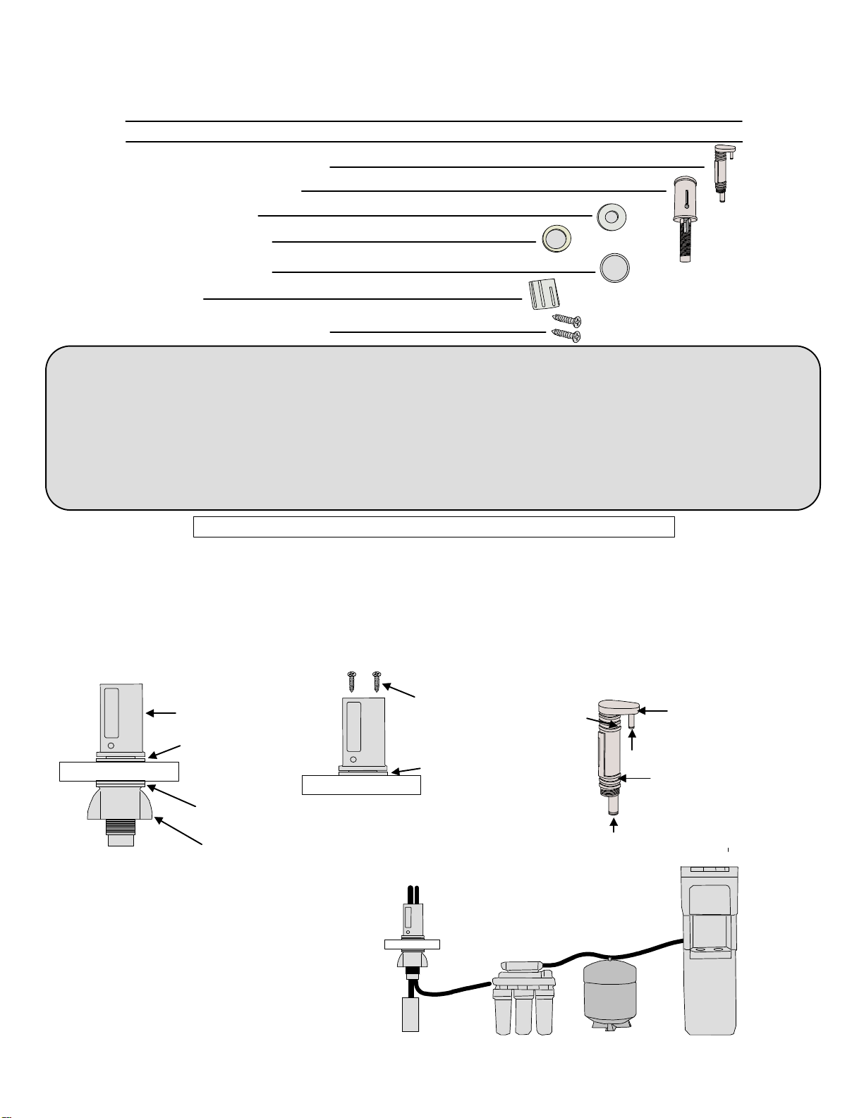
LIST OF PARTS ENCLOSED
Please read the instructions once through before starting.
AG110-004 INSTALLATION INSTRUCTION
AG110-004
1- Reverse Osmosis Air Gap Drain
1- Counter Top Housing
1- Mounting Washer
1- Rubber Trim Washer
Always comply with local plumbing codes during installation
2- #6-1", Phillips Flat Head Screws
The AG110-004 Reverse Osmosis Filter Air Gap prevents back-flow from the discharge tubing into
the RO system. The discharge water flows out of the reverse osmosis system into the air gap
inlet, passes air-gap, and then down to the drain piping.
• Easy and secure tubing connection to the inlet and the outlet ports of the air gap.
• Tested for maximum 0.4 GPM (1.5 Liters/minute)
• Suggested flow rate 1 to 16 oz/minute (30 to 500 milliliters/minute)
• UPC® listed, tested for compliance with IPC and NSF standards
1. Make sure that the flow rate output of the RO equipment meets AG110-004 flow capacity limits of
0.4 GPM (1.5 Liters/minute).
2. Check inlet and outlet ports marking on the
AG110-004 body. (see FIG 1-2)
2. Secure counter top housing, as shown. (See FIG 1-1). For mounting option 1, drill 3/4-inch hole on for air
gap housing installation.
1- Cover
1- Wing Nut
Inlet Port
Outlet Port
Reverse Osmosis
Air Gap Drain
Inlet Marking
Outlet
Marking
Fig 1-2
Counter Top
Housing
Rubber Trim
Washer
Mounting Washer
Wing Nut
-OVER-
Water supply
Water Cooler
RO System
Discharge
water
Drain Pipe
RO Tank
Fig 1-3
3. AG110-004 is a gravity flow device and must
have an outlet poly tubing feeding directly into a
drain without kinks, loops, sagging, or bends. The
AG110-004 is mounted on a counter to help the
discharge water to flow freely through the outlet
tubing. (See FIG 1-3)
Fig 1-1
Apply
mounting
screws from
the top
Mounting option 1
Mounting option 2
Note: Break bottom portion of the countertop
housing.The wing nut and mounting washer
are not usable in this case.
Rubber Trim
Washer


