Air Liquide PRIMEJET User manual

Technical cylinder pressure regulators
User manual
PRIMEJET / PRIMEFLOW

Description according to EN ISO 2503
1. Cylinder valve
2. Inlet connection
3. High pressure gauge
4. Low pressure gauge
(gauge l/min in pressure regulator with
flowmeter gauge)
5. Pressure adjustment screw
6. Shut-off valve
7. Outlet connection
(E.g.. hose nozzle with union.
Nut not included.)
8. Pressure relief valve
9. Regulating office throttle (for pressure
control), only in pressure regulators with
flowmeter gauge
10. Type designation, name of manufacturer
and/or distributor
Marking gas type
A = Acetylene
O = Oxygen
P = LPG
N = CO2, Nitrogen, Inert gas
H = Hydrogen
D = Compressed air
M = Methane/Natural gas
Y = MPS
P1 = Highest admission pressure
P2 = Maximum outlet pressure or flow
Device class according to EN ISO 2503
Date of production – Code
Manufacturer Code
This operating manual is intended to ensure the
safe use of the pressure regulator for its intend-
ed purpose. Reading and following instruction
in the operating manual contributes to prevent-
ing hazards, reduces downtime and increases
the reliability and service life of the devices.
THIS OPERATING MANUAL
MUST ALWAYS REMAIN
AVAILABLE WITHIN REACH.
Safety instructions see also Point 2: in case of
doubt the manufacturer or distributor should
be contacted.
2
1310 42 8
5
6
9
7

1 Use
1.1 Intended use
These cylinder pressure regulators are intend-
ed for use with compressed gases released
under pressure, on pressurized gas cylinders
up to 300 bar filling pressure (depending on
technical design) as well as for liquid gases,
to reduce the corresponding cylinder pressure
and to keep the desired working pressure con-
stant. The pressure regulator must only be used
for gases for which a symbol is present on the
pressure regulator (see symbols Point 3).
1.2 Unintended use
• Pressure regulation valves must not be
used for liquids
• Pressure regulators must not be operat-
ed in ambient temperatures below -20 °C
and above 60 °C
• Do not use pressure regulators for ag-
gressive gases such as ethylamine, dieth-
ylamine, ammonia etc.
1.3 Directive 97/23/EC:
Pressurised equipment (PED)
AIR LIQUIDE equipment of DN < 25 mm
(e.g. pressure regulators, valves, non return
valves…) satisfy to requirement of article 3§3
of 97/23/EC directive and at the state of
the art. Consequently, these equipments shall
not be CE marked as defined in article 15.
By design, these equipment may inte-
grate pressure relief valves or burst disks.
In this case, those ones shall neither be CE
marked according to paragraph 2 of annex II.
In other case, pressure relief valves and burst
disks shall be CE Marked.
2 Safety instructions
All indications labeled with this symbol
are considered as special safety instruc-
tions.
2.1 The pressure regulators conform to the
recognized state of the art, as well as the
requirements of existing standards.
•No changes or alterations may be per-
formed without the manufacturer‘s per-
mission.
2.2 No adapters should be installed between
the cylinder valve and the cylinder pres-
sure regulator.
Improper operation, or use for purposes
other than those intended can create
hazards for the user and other persons,
as well as damage to the pressure regu-
lator.
2.3 Regulations that are applicable in
Germany:
2.3.1 Accident prevention regulations /
DGUV rules
• 100-001“Principles of prevention“
• 113-001 “Explosion prevention rules“
Name plate
• 100-500 “Operation of work equipment“
2.3.2 Laws, directives, technical regulations
Product safety law (ProdSG) with the
specific:
• Product safety directives (ProdSV),
e.g.Explosionprotectiondirective(11.ProdSV)
or Pressure device directive (14. ProdSV)
5. Dimensional drawing
• Work safety directive with Appendix 1 – 3
• Work safety technical rules (TRBS)
• Hazardous materials technical rules
(TRGS)
• Plant safety technical rules (TRAS)
2.3.3 Bulletins, norms and guidelines
• Pressure equipment directive, 2014/68/EU
• Bulletin Use of compressed gas cylinders
(DVS 0212)
• Refer to the safety data sheets of each
specific gas type
2.4 Regulations that are applicable in Austria:
• Employee protection law ASchG

• Work equipment directive (AM-VO)
BGBL. II. Nr. 164/2000 igF.
• General operating instructions for acety-
lene welding and cutting equipment ac-
cording to § 26 para. 4 of the AM-VO.
2.5 Regulations that must be observed in
Switzerland:
• 832.20 Federal Act on Accident Insu-
rance (AIA)
Art. 82 The employer is obligated to
take all the necessary steps to prevent
workplace accidents and occupational
diseases, which, according to experience,
are necessary, can be applied according
to the latest technology and are appropri-
ate for the respective circumstances.
• 822.11 Employment Act, EmpA
Art. 6 The employer is obligated to take
all the necessary steps to protect the
health of his employees, which, according
to experience, are necessary, can be ap-
plied according to the latest technology
and are appropriate for the respective
type of business.
• 832.30 Ordinance on the Prevention of
Accidents and Occupational Diseases
(APO)
Art. 3 To safeguard occupational safety,
the employer must make all the arrange-
ments and protective measures that
correspond with the provisions of this
Ordinance and the other provisions ap-
plicable for his business governing oc-
cupational safety, as well as all other
recognized technical regulations relating
to safety and occupational health. The
employer must ensure that the effective-
ness of the protective measures and
protective devices are not compromised.
If buildings, parts of buildings, work
equipment (machines, apparatus, tools
or plants used at work) or work prac-
tices are changed or new substances
are being used, the employer must adapt
the protective measures and protective
devices to suit the new conditions.
Art. 6 The employer must ensure that
all employees working in his company,
including employees of another company,
are informed of the dangers involved in
their activities and are informed of the
measures to take in order to prevent them.
This information and instructions must be
relayed at the time the individual is hired
and on the occasion of every significant
change in the working conditions and re-
peated if necessary.
• 819.121 Ordinance on the Safety of
Pressure Equipment (Pressure Equipment
Regulation, DGV)
• 832.312.12 Ordinance on the Safety and
Health Protection of Workers in the Use
of Pressure Equipment (Use of Pressure
Equipment Ordinance, DGVV)
• 930.111 Ordinance on Product Safety
(ProdSO)

3 Starting operation
The sequence must be strictly
respected!
Explosion hazard! All parts such as tools
and hands that come into contact with
oxygen must be kept free from oil and
grease.
3.1 Before starting work, the instructions in
this operating manual must be read and
followed during the work!
3.2 Check if the pressure regulator is suitable
for the intended gas type and pressure
(see symbol Point 3).
3.3 Check if the cylinder valve connector and
the seal are clean and undamaged. In
case of any damage, the pressure regula-
tor must not be connected.
Before screwing on the pressure
regulator, open the cylinder valve once
briefly and close it again in order to blow
out any possible dirt. Do not stand in
front of the valve when doing this or hold
your hand in front of the valve. (except
for hydrogen and hydrogen mixtures,
propane, corrosive, toxic and irritant
gases, and flammable test gases). Ensure
good ventilation.
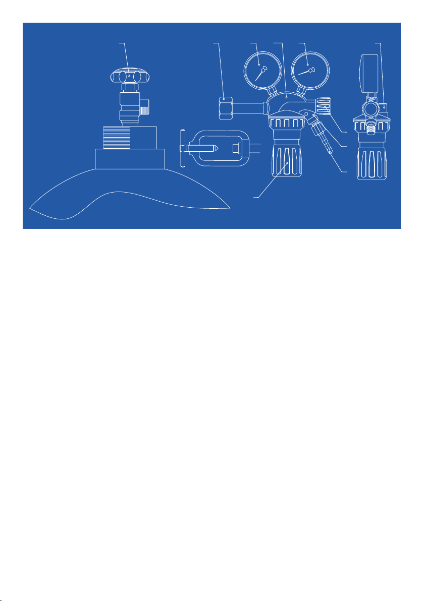
3.4 Connect the regulator with screw con-
nection to the bottle valve (1) using a
suitable spanner or connection bracket
(2) in a gas-tight manner. For regulators
with manual connection (O-ring seal), this
screw connection must be tightened by
hand. No tools must be used for manual
connection. The mounting position of the
regulator must always be vertical in rela-
tion to the pressure gauges.
3.5 Connect the hose to the hose connector
on the outlet stud (7) and to the consum-
er device. Hoses and hose connections
(hose nozzles) shall be used according to
actual and related standard. Secure the
hoses with suitable hose clips.
3.6 Adjusting the pressure
Before releasing the gas into the system, check
the following:
1. Correct version of the cylinder pressure
regulator
2. All indicators at zero
3. Pressure fully turned off on the pressure
adjustment screw (5) (anticlockwise)
4. Re-adjustment valves are closed.
Then close the shut-off valve (6) and release
pressure and pressure regulator by unscrewing
the pressure adjustment screw (5). Open the
cylinder valve slowly, the high-pressure gauge
(3) indicates the cylinder pressure. Open the
shut-off valve (6) and slightly open the corre-
sponding shut-off valve of the consumer device.
Then screw down the pressure adjustment
screw (5) to set the desired outlet pressure
(operating pressure) and check it on the low
pressure gauge (4). Correct the pressure set-
ting if the pressure dips.
Carry out leak test with Air Liquide leak
detection spray!
4 Stopping operation
• For short shutdown periods: close the
shut-off valve on the pressure regulator.
• For longer shutdown periods: Close the
cylinder valve, release pressure, pres-
sure regulator has zero pressure, loosen
pressure adjustment screw (5). Close the
shut-off valves on the pressure regulator
and the consumer device. Never tighten
or loosen screw connectors while they
are under pressure!

5 Operation and
maintenance note
5.1 Always protect the pressure regulator
from damage (visual inspection at regular
intervals).
The factory settings of the connection
seals must not be changed.
5.2 Ensure that the connector seals, sealing
surfaces and gauges are in perfect con-
dition.
If a fault occurs, for example if the
outlet pressure rises when output = 0,
if there are leaks into the atmosphere,
the guages are defective, or when the
safety valve is activated, shut off the
pressure regulator , close the cylinder
valve immediately.
Air Liquide recommends annual periodic in-
spections of the pressure regulator by compe-
tent, authorized personnel.
Faults that occur can have many causes.
For your own safety, avoid tampering or
making repairs on your own.
6 Repairs
Repairs to the pressure regulators must
only be done by competent and trained
personnel in authorized specialist work-
shops. Only original spare parts must be
used for repairs.
6.1 If unauthorized repairs or changes are
made by the user or a third party without
permission from the manufacturer, then li-
ability for the consequences is rescinded.
7 Cylinder pressure regula-
tors with flow meter gauge
For these pressure regulators, points 1 to 7
in this operating manual also apply. The flow
quantity set by the pressure adjustment screw
(5) is indicated on the flow meter gauge (4). In
pressure regulators with a flow meter gauge, a
regulating office/ throttle (for pressure control)
(9) is built in. Check if a regulating office/ throt-
tle (for pressure control) is already installed in
your equipment. If yes this must be removed
because the mounting holes are not adapted to
the pressure regulator.
8 Indications to Cylinder
pressure regulator having
Flowmeter
Setting of the required flow:
1. Close shut-off valve (6)
2. Open slowly cylinder valve (1).
The inlet gauge (3) is indicating the cylin-
der pressure.
3. Open shut-off valve (6) and correspond-
ing shut-off valve of the implement.
4. Set the desired flow by adjustment valve
(6).
9 Guarantee
The standard warranty period is one year from
the date of delivery in accordance with the
general terms and conditions of Air Liquide
Deutschland GmbH, Air Liquide Austria GmbH
and Carbagas AG. The standard warranty pe-
riod is only valid for goods that have been used
according to the operating manual and general-
ly applicable industry practices and standards.
10 Note
Please use the product only for the purpose
that Air Liquide intended and only if you are
competent in the application and follow the
technical safety guidelines or safety proce-
dures. If there are any doubts related to the
use of the product, request specific Air Liquide
product information beforehand or talk to an Air
Liquide specialist.

424 000 512/A:01 vom März 2021 / RKI-tk-TSA · Rev. 1/ab_ce ∙ Änderungen vorbehalten ∙ Alle Angaben ohne Gewähr
Air Liquide Austria GmbH
Sendnergasse 30
2320 Schwechat
Tel: +43 810 242427
www.airliquide.at
Carbagas AG
Hofgut
3073 Gümlingen
Tel: +41 31 95 05050
info@carbagas.ch
www.carbagas.ch
Contact
Air Liquide Deutschland GmbH
Fütingsweg 34
47805 Krefeld
Tel: +49 (0) 2151 379 - 0
www.airliquide.de
The QR Code leads you to the online version of this manual.
This manual suits for next models
1
Table of contents
Other Air Liquide Controllers manuals
Popular Controllers manuals by other brands

Honeywell
Honeywell T775 Series Application guide and cross reference

AutomationDirect
AutomationDirect CLICK Product Dimensions and Installation

CUTES
CUTES CT-2000F Series Instruction

Show Tec
Show Tec ColorCue 1 manual

Mitsubishi Electric
Mitsubishi Electric FX5-ENET user manual

Hunter
Hunter 27178 installation guide