Megmeet MCCD Series Service manual

MCCD series display control integrated
PLC user quick reference manual
Thank you for using MCCD series PLC of Megmeet. Before using the
PLC product, please carefully read this booklet so as to better
understand it, fully use it, and ensure safety.This user manual is to offer
you a quick guide to the design, installation, connection and
maintenance of MCCD series PLC.This quick reference manual is
used for the design, installation, connection and maintenance of the
MCCD series PLC. It is convenient for users to consult the required
information on the spot, as well as the introduction of the relevant
optional accessories, FAQ, etc., for easy reference.
This manual for the following members:
MCCD-1616BMD1
MCCD-1616BMD2
MCCD-1616BMD3
MCCD-1616BMD4
MCCD-1212BMD1
MCCD-1212BMD2
MCCD-1212BMD3
MCCD-1212BMD4
Version A02
Revision date Sep 25, 2019
BOM
1. Appearance and parts name
Front view
Back view of MCCD-1212BMD
Back view of MCCD-1616BMD
2. Model specification
3. Installation
3.1 Environment temperature
1. Ambient temperature range: -5℃~ 55℃.
2. Humidity: <85%RH, no condensation.
3. When the ambient temperature exceeds 55℃for a long time, it is
better to choose a well-ventilated place.
3.2 Installations
Places free from corrosion, flammable and explosive gases and
liquids.
A firm, vibration-free place.
The PLC is designed for the application of installing environment
II standard and pollution level 2.
3.3 Installation dimensions

3.4 Installation method
The PLC must be installed horizontally on the back panel of the
electrical cabinet. Install it up and down and keep the distance between
the PLC and the equipment or cabinet wall above and below not less
than 20cm. Installation in other directions is not conducive to heat
dissipation of the PLC, and there should be no heating equipment
under the PLC.
Make holes in the panel according to the size of the opening. The
MCCD series display control integrated PLC is embedded from the
front of the panel, and the text display is fixed with four randomly
equipped mounting brackets. See the operation diagram below:
3.5 Cable connections and specifications
When wiring products, it is recommended to use multiple copper wires
and prefabricate insulated terminals to ensure the quality of wiring. The
sectional area and type of the recommended conductor are shown in
the table below.
Cable
Position
Allow wire
number
Recommended
stripping length
Power
terminal(3PIN)
Back
16~28AWG
6.5mm
Communication
terminal(10PIN)
Back
16~28AWG
6.5mm
DA output
terminal(6PIN)
Back
16~28AWG
6.5mm
AD input terminal
(4PIN)
Back
16~28AWG
6.5mm
TC input terminal
(8PIN)
Back
16~28AWG
6.5mm
PT100 input
terminal(4PIN)
Back
16~28AWG
6.5mm
Digital input
terminal(20PIN)
Back
16~28AWG
6.5mm
Digital output
terminal(20PIN)
Back
16~28AWG
6.5mm
For security (to prevent electric shock and fire accident), and reduce
the noise, the module of grounding terminal shall be in strict
accordance with the national electrical code requirements, grounding
resistance should be less than 0.1 Ω. When grounding multiple
modules, single point grounding should be adopted, and the ground
wire cannot form a circuit. As shown in the figure below:
Error Correct
4. Power supply
Item
Unit
Mix.
value
Type
value
Max.
value
Remark
The range of
input voltage
Vdc
20.4
24
30
Normal start-up
and working
range
Input current
A
0.45
0.5
0.55
Normal
temperature rated
full load
5. Terminal
5.1 User terminal

The terminal definition of MCCD-1212BMD1/2/3/4
Remark
Explanation
24V+,24V-
Power supply DC24V
PE
Ground
A0,B0
RS485 port 0(COM0)
A1,B1
RS485 port 1(COM1)
A2,B2
RS485 port 2(COM2)
CANH、CANL
CAN port 0
X00~X01,S/S
High-speed input port 0~1,input common
terminal
X02~X13,S/S
Switch input terminal 02~13,
input common
terminal
Y00~Y02,COM0
High-speed output port 0 ~2,output
common terminal 0
Y03~Y07,COM1
The channel of switch output3 ~7,output
common terminal 1
Y10~Y13, COM2
The channel of switch output10~13,output
common terminal 2
VI1+,VIO1-,IO1+,VI2+,
VIO2-,IO2+
The channel of analog output1 ~2
(Compatible with voltage and current)
VI1+,VI1-,VI2+,VI2-
The channel of analog output 1 and
2(voltage or current)
PT1+,PT1-,PT2+,PT2-
PT100 input channel 1 and channel 2
L1+,L1-,L2+,L2-,L3+,
L3-,L4+,L4-
TC input channel 1,channel 2,channel 3 and
channel 4
ETH
Ethernet
USB1
USB flash drive interface for program
upgrade
USB2
USB interface for program debugging and
downloading
The terminal definition of MCCD-1616BMD1/2/3/4
Remark
Explanation
24V+,24V-
Power supply DC24V
PE
Ground
A0,B0
RS485 port 0(COM0)
A1,B1
RS485 port 1(COM1)
A2,B2
RS485 port 2(COM2)
CANH、CANL
CAN terminal 0
X00~X01,S/S
High-speed input port 0~1,
input
common terminal
X02~X17,S/S
Switch input terminal 02 ~17 ,
input common terminal
Y00~Y02,COM0
The channel of high-speed
output 0 ~2,output common
terminal
Y03~Y07,COM1
The channel of switch output3~
7,output common terminal 1
Y10~Y17, COM2
The channel of switch output10~
17,output common terminal 2
VI1+,VIO1-,IO1+,VI2+,VIO2-,IO2+
The channel of analog output1~
2(Compatible with voltage and
current)
VI1+,VI1-,VI2+,VI2-
The channel of analog output 1
and 2(voltage or current)
PT1+,PT1-,PT2+,PT2-
PT100 input channel 1 and
channel 2
L1+,L1-,L2+,L2-,L3+,L3-,L4+,L4-
TC input channel 1,channel
2,channel 3 and channel 4
ETH
Ethernet
USB1
USB flash drive interface for
program upgrade
USB2
USB interface for program
debugging and downloading
5.2 Communication port
Name
Supported
protocols
Position
Physical
layer
Communication port 0
Modbus ( slave
station)
COM0
(A0 ,B0)
RS485
Communication port 1
Modbus (master
and slave station)
free port
COM1
(A1 ,B1)
RS485
Communication port 2
Modbus (master
and slave station)
COM2
(A2 ,B2)
RS485
Communication port 3
CAN free port
CAN0(H,L)
CAN
Communication port 4
Ethernet
ETH
TCP/IP
Communication port 5
USB host
USB1
USB
Communication port 6
USB slave
USB2
USB
Note: 1. Communication port 2 is HMI resource, which needs to be set
in MEGVIEW2 for use. Modbus slave station is the default.
Communication port 4, 5 and 6 are HMI resources, which need to be
set in MEGVIEW2 for use
6. Switching characteristics of input and output
6.1 Switching input characteristics and signal
specifications
The counter input port has a maximum frequency limit. If the limit is
exceeded, the count may be inaccurate or the system may not function
properly. Please arrange the input port reasonably and select the
appropriate external sensor.
The PLC provides port "S/S" for selecting whether the input signal is
source input or leak input.
6.1.1 Transistor input specifications
Item
High-speed input
Normal input
Input resistance
3.3kΩ
4.3kΩ
Input current
6.5mA (Type value)
5.3mA (Type value)
ON voltage/current
DC18V /4.5mA
DC18V /3mA (Mix.

(Mix. value)
value)
OFF voltage/current
DC4V /1mA (Max.
value)
DC4V /1mA (Max.
value)
Speed requirement
Single channel
frequency ≤50Khz,2
channels total
frequency≤80khz
≤100HZ
6.1.2 Wiring method
Leaky input: connect S/S terminal to +24V terminal. NPN sensors can
be connected in this way. The internal equivalent circuit and external
connection mode of leakage input mode are shown in the figure below.
Source input: Short connect S/S terminal to COM terminal. This way
can be connected to the PNP sensor. The internal equivalent circuit
and external connection mode of source input mode are shown in the
figure
Transistor input specification
6.2 Switching output characteristics and signal
specifications
The output terminals of MCCD series are divided into several groups,
each group is electrically isolated, and the output contacts of different
groups are connected to different power circuits. The output can be
divided into two types: relay and transistor. Transistor output stages
can only be used in DC 24V load circuits with attention to power
polarity. The inductive load of DC circuit should be considered to
increase the continuation diode; For the inductive load of ac circuit, the
external circuit should consider the RC instantaneous voltage
absorption circuit. As shown in the figure below.
Special function of output port
The transistor output type main module contains three high-speed
output ports Y0,Y1 and Y2. The three channels can independently
output high-speed pulse. Provides high speed I/O instructions and
location instructions to manage high speed output channels. For high
speed output, it is recommended to use double stranded shielding wire
for the corresponding input port, and to ground the shielding layer
(connected with the terminal or connected to the signal ground) to
improve disturbance immunity.
6.2.1 High-speed transistor output specifications
Item
Index
Power of loop circuit
<30Vdc
Circuit insulation
Optocoupler isolation
Min. load
5mA(5~24VDC)
Maximum output current of
resistive load
0.5A/point;
Maximum output current of
inductive load
7.2W/24VDC
ON response time
10uS
OFF response time
10uS
Response frequency
≤100kHz
6.2.2 Normal transistor output specifications
Item
Index
Power of loop circuit
<30Vdc
Circuit insulation
Optocoupler isolation
Min. load
5mA(5~24VDC)
Maximum output current of
resistive load
0.5A/point;
Maximum output current of
inductive load
7.2W/24VDC
ON response time
0.5ms
OFF response time
0.5ms
Response frequency
≤100Hz
6.2.3 Relay output specifications
Item
Index
Circuit insulation
Relay isolation
Contact load (resistive)
5A 250VAC/30VDC
Switching voltage
250VAC/30VDC

Switching current
2A
Switching power
1250VA/150W
ON response time
10ms
OFF response time
10ms
Output common terminal
Each common terminal is isolated
from each other
7. Analog input and output characteristics
7.1 Wiring method
The specific connection is shown in the following figure:
The wire method of analog input
The wire method of analog output
The wire method of thermal resistance input
The wire method of TC input
* Double stranded shielded cable access is recommended. Cables should be kept away
from power lines or other wires, user terminals, extension cables and interface
extension cables that may cause electrical interference.
* If the input signal fluctuates or there is electrical interference in the external wiring, it is
recommended to connect a smooth capacitor (0.1uf ~ 0.47uF/25V).
* It is recommended to use connection cables of less than 100m in length to reduce
measurement errors and noise interference.
7.2 Specifications
7.2.1 Current and voltage input channel specification
Item
Index
Conversion
speed
15ms/channel(Normal),6ms/channel(high-speed)
Analog
input
range
Voltage
input
0VDC~+10VDC,input
resistance 1MΩ
The attributes of each
channel can be set
individually through
the X-Builder
programming software
Current
input
0mA ~+20mA ,input
resistance 250Ω
Digital output
Scope:0~+2000
Resolu
tion
Voltage
input
5mV
Current
input
10uA
Accuracy
Full load ±1%
Isolation
Analog and digital circuits are not isolated
7.2.2 Analogy output channel specification
Item
Index
Conversion speed
2ms/channel
Analog
output
Voltage output
0 ~ + 10 VDC, external load
impedance ≥2 k Ω
Current output
0 ma ~ + 20 ma, external load
impedance ≤500 Ω
Digital
output
Voltage output
Default setting: 0 ~ +2000
Current output
Default setting: 0 ~ +2000
Resolution
Voltage input
5mV
Current input
10uA
Accuracy
Full load ±1%
Isolation
Analog and digital circuits are isolated,
analog channels are not isolated.
7.2.3 Thermal resistance input channel specifications
Item
Index
Thermal resistance type
Pt100、Cu100、JPt100、Cu50、Ni120
Temperature control
output
Transistors and analog output are
configurable
The sampling period
About 100ms
Temperature control cycle
1~100,unit 1s,The specific value is
determined by the characteristics of the
temperature control object
Control method
Hand control,ON/OFF control,PID
control

Sensor type
and
temperature
range
Pt100
-150℃~600℃(-238℉~1112℉)
JPt100
-150℃~500℃(-238℉~932℉)
Cu100
-30℃~120℃(-22℉~248℉)
Cu50
-30℃~120℃(-22℉~248℉)
Ni120
-80.0℃~280.0℃(-112.0℉~
536.0℉)
Thermal resistance
Input range±0.5%
7.2.4 TC input channel specifications
Item
Index
Input single
Thermocouple
type
K、J、E、N、T、R、S、B
Output
method
Transistor
output with
open gate
Loop power voltage :5V ~24V ;Max.
Power voltage of loop :30V ;Loop
current:0.3A/24Vdc;Leakage current
when open : < 0.1mA/30Vdc ;Min.
load:5mA(5Vdc~24Vdc)
The sampling period
About 100ms
Temperature control cycle
1~100,unit 1s,The specific value is
determined by the characteristics of
the temperature control object
Control method
ON/OFF control ,Hand control,single
PID control
Rate
temperature
range
K type
-100℃~1200℃(-148℉~2192℉)
J type
-100℃~1200℃(-148℉~1112℉)
E type
-100℃~850℃(-148℉~1562℉)
N type
-100℃~1200℃(-148℉~2192℉)
T type
-200℃~300℃(-328℉~572℉)
R type
0℃~1600℃(32℉~2912℉)
S type
0℃~1600℃(32℉~2912℉)
B type
400℃~1800℃(752℉~3272℉)
Accuracy
Thermocouple
Input range±0.3 % , Ambient
temperature compensation error<=2℃
Thermal
resistance
Input range±0.5%
Isolation
Channels are isolated from each
other
8. Common problems and solutions
When the module cannot work normally, please check in turn:
(1) The connection of power lines and the status of related switches
and protective appliances to ensure that the module has been reliably
supplied;
(2) Whether the connection of user terminals is firm;
If the above inspection is still unable to work, you can refer to the
following table.
phenomenon
Possible reason
Countermeasures
RUN and ERR are
OFF
Out of voltage or low
voltage
Check power supply
condition and
exclude
The power switch is
off or the fuse is
blown
Check the condition
of switches, wires or
fuses to exclude
them
Abnormal power
connection
Power plate damage
Check and confirm
whether the voltages
between 24V+ and
24V- terminals are in
normal range
RUN and ERR are
flashed intermittently
in the same time
The power supply is
unstable
The module is
damage
RUN is OFF
Shut down remotely
by upper computer
equipment
Make the upper
computer start up
remotely
System error outage
Check by assistant
ERR single light is
ON
System error outage
Check with an
assistant and consult
the errata manual
1. Warranty scope refers to the programmable controller body.
2. The warranty period is 18 months. If the product breaks down or is
damaged during normal use, our company will repair it free of charge.
3. The warranty period starts from the date the product is manufactured.
Machine code is the only basis for judging the warranty period.
Equipment without machine code shall be treated as under warranty.
4. Even within the warranty period, a maintenance fee will be charged
if:
Failure of the machine caused by failure to operate in
accordance with the user's manual.
Damage to machinery caused by fire, flood, abnormal voltage,
etc.
Damage caused when a programmable controller is used for
abnormal functions.
Self-disassemble the programmable controller.
5. The service fee shall be calculated according to the actual cost. If
there is another contract, the contract shall take precedence.
6. If you have any questions, please contact the agent or our company
directly.
SHENZHEN MEGMEET CONTROL TECHNOLOGY CO.,LTD
Add:floor 5, tower B, qinghua information port, langshan road, north
district, science and technology park, nanshan district, shenzhen
Tel:400-6662163
Fax:(+86)0755-26897197
Zip code:518067
Web:www.megmeet.com

This manual suits for next models
8
Table of contents
Other Megmeet Controllers manuals

Megmeet
Megmeet MV820 User manual
Megmeet
Megmeet MC5000 Series User manual
Megmeet
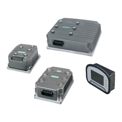
Megmeet L6 Series User manual
Megmeet
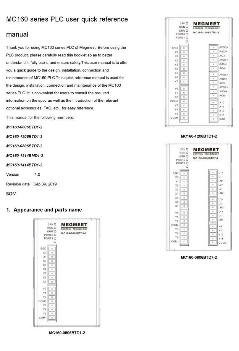
Megmeet MC160 PLC Series User manual
Megmeet
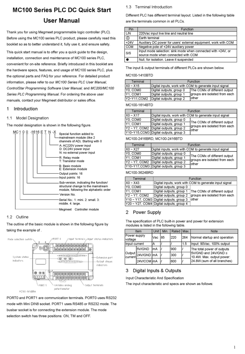
Megmeet MC100 Series User manual
Megmeet
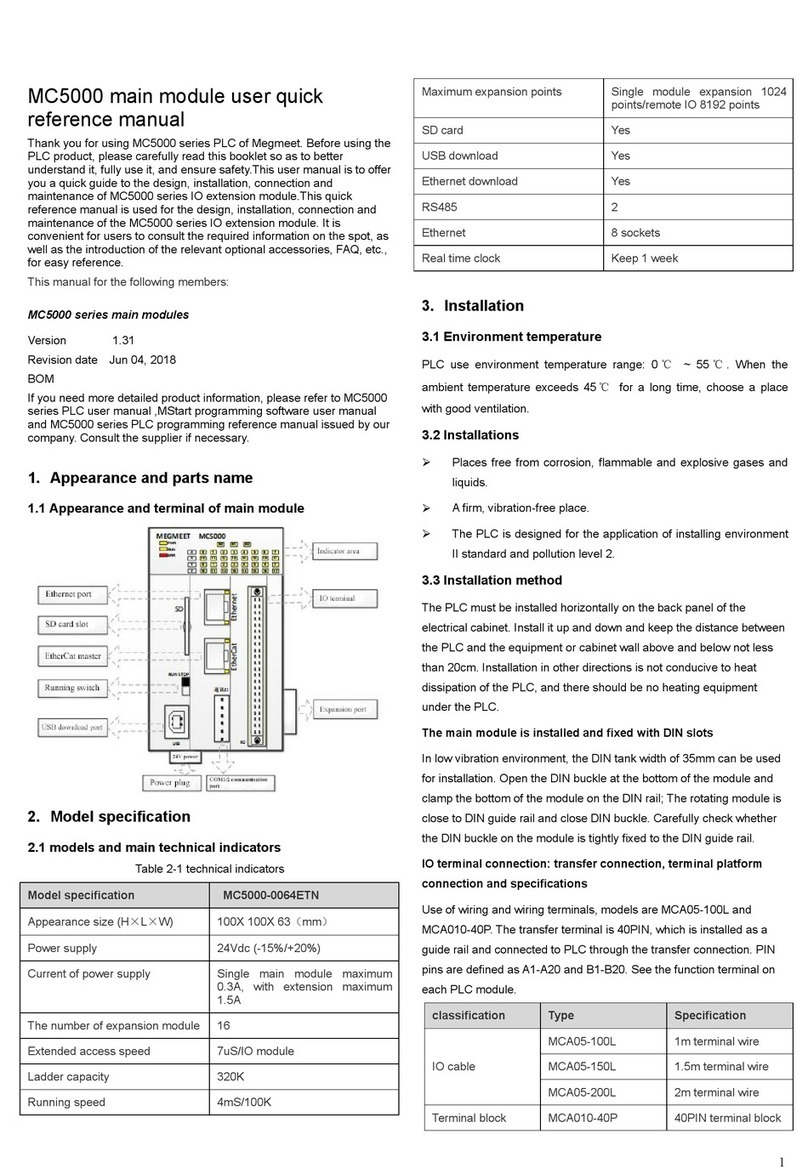
Megmeet MC5000 Series User manual
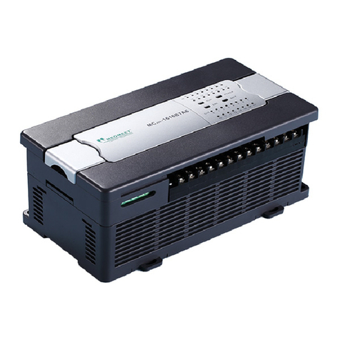
Megmeet
Megmeet MC200E Series Manual

Megmeet
Megmeet MC5000 Series User manual
Popular Controllers manuals by other brands
Preferred
Preferred JC-23D2 Installation & operation instructions
Festo
Festo VZXA Series operating instructions
tecatlantis
tecatlantis LUMINUS operating manual
Extron electronics
Extron electronics MLC Plus 84 D Setup guide
Pixel
Pixel EM-181Mu user guide
National Instruments
National Instruments cFP-22 Series manual
