DVC2000 Digital Valve Controller
July 2009
1-2
Instrument Description
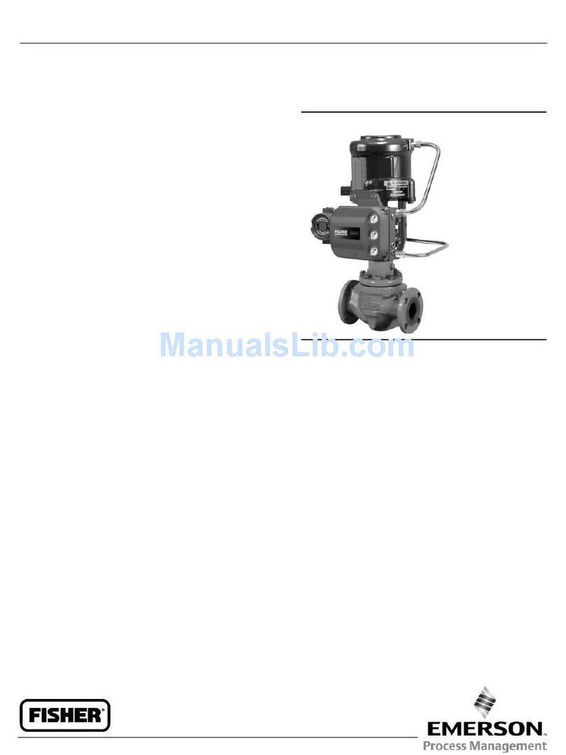
The DVC2000 digital valve controller is a
communicating, microprocessor-based current-to-
pneumatic valve positioner (see figure 1-1). It is
designed to replace standard pneumatic and
electro-pneumatic valve positioners.
In addition to the traditional function of converting an
input current signal (4-20 mA) to a pneumatic output
pressure, the DVC2000 digital valve controller
communicates via a local display panel and/or via the
HARTprotocol. An option is available which
provides isolated circuitry for two (2) integrated limit
switches (for open/close valve indication) and a valve
position transmitter (for separate valve position
feedback).
Terminology
Instrument Level— There are four (4) levels of
functionality available: AC, HC, AD and PD.
AC—This level provides the capability to setup and
calibrate the positioner through the LCD or the 375
Field Communicator.
HC—This level provides additional capability for
advanced configuration of the positioner (such as
travel limits/cutoffs, custom characterization, and
minimum open/closing time). Also, information is
available through the HART protocol for diagnostic
alerts such as travel deviation, cycle count, and
travel accumulation.
AD—This level provides advanced diagnostic
capabilities for performance testing. When used with
ValveLink software, instrument health can be
evaluated with tests such as Valve Signature, step
response and dynamic error band. The software
program provides detailed analysis with graphics.
PD—This level provides automated, non-intrusive
testing of the operating performance of the control
valve assembly. When used with ValveLink
software, tests to isolate component degradation
can be run on the valve assembly without affecting
the process.
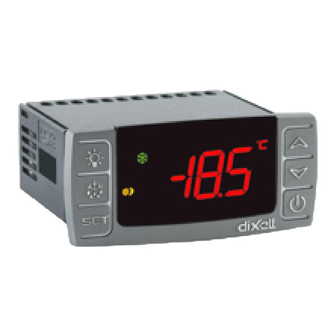
Local Interface— The DVC2000 comes standard with
a Liquid Crystal Display (LCD) and four (4)
pushbuttons. The local interface provides the
capability to setup and calibrate the positioner and
view basic diagnostic messages.
Figure1-1. FIELDVUE DVC2000 Digital Valve Controller
W8755
Magnet Assembly—This is the feedback component
that is mounted directly to the valve stem. It supplies a
magnetic field that is sensed by the digital valve
controller.
Option Boards—The DVC2000 digital valve controller
is available with two (2) limit switches and a valve
position transmitter. The option boards include the
additional circuitry and terminations that are required
to support these output signals.
Pole Piece—Inserted into the DVC2000 housing and
protruding through the back of the instrument is a
two-pronged fork that houses the magnetic sensor for
position feedback.
Scope of Manual
This instruction manual includes specifications,
installation, initial setup, configuration, operation,
troubleshooting, and maintenance information for the
DVC2000 digital valve controller.
This manual describes using the 375 Field
Communicator to setup and calibrate the instrument.
To accomplish these functions, as well as diagnostic
and performance tests with ValveLink Software, refer
to the ValveLink Software help.
Do not install, operate, or maintain a DVC2000 digital
valve controller without being fully trained and qualified
in valve, actuator, and accessory installation,
operation, and maintenance. To avoid personal injury
or property damage, it is important to carefully read,
understand, and follow all of the contents of this
manual, including all safety cautions and warnings. If
you have any questions regarding these instructions,
contact your Emerson Process Management sales
office before proceeding.
1
