DINUY RE KNT 004 User manual
RE KNT 004
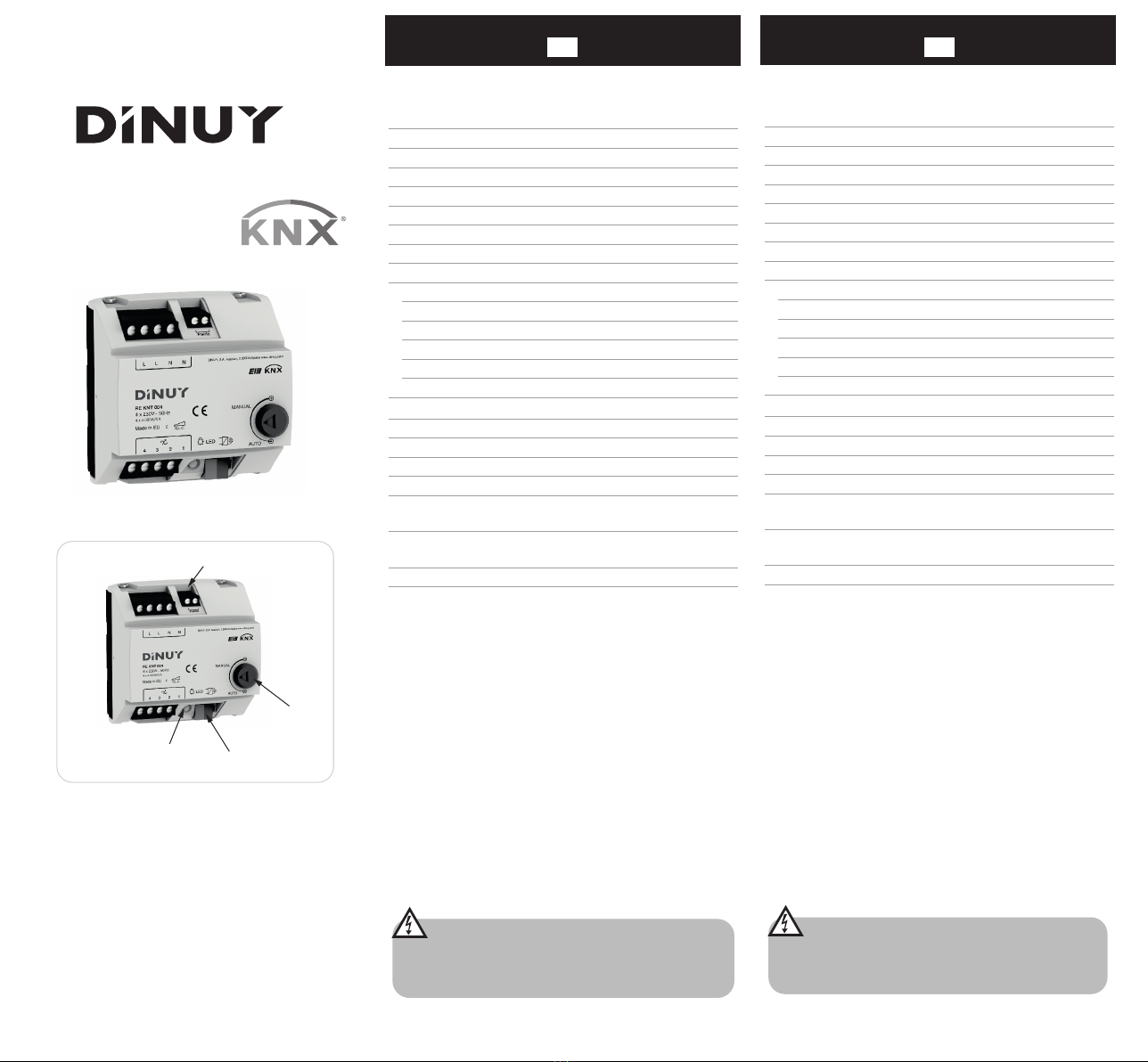
A
C
B
D
ACTUADOR DE REGULACIÓN UNIVERSAL DE 4 CANALES
ESPECIFICACIONES TÉCNICAS
DESCRIPCIÓN
Actuador de regulación modular universal, de 4 canales, por control de fase (principio o fin
de fase), siendo válido para diferentes tipos de carga R, L ó C:
- Incandescencia y Halógenas 230V.
- Halógenas con transformador electrónico.
- Lámparas LED 230V~ regulables.
- Lámparas LED 12V~ regulables con transformador electrónico.
Dispone de 4 canales de salida independientes.
Incorpora un Potenciómetro (D), el cual permite comprobar, manualmente, el funcionamiento
correcto del regulador, sin necesitada de conectar el Bus KNX:
· Manual (cualquier posición por encima del mínimo): con el propio potenciómetro es
posible regular las lámparas sin necesidad de conectar el Bus.
· Automático (al mínimo): funcionamiento a través del Bus.
Protegido frente a sobrecargas y cortocircuitos. Incorpora protección térmica de
funcionamiento rearmable.
Entrada anti-pánico (A), para sistemas de seguridad: en caso de emergencia, habilitando
esta entrada, las lámparas se encenderán al máximo sin hacer caso a la regulación.
Programación y puesta en marcha mediante ETS4 o versiones posteriores. Dispone de
terminal de conexión estándar (C).
Tensión Nominal 230V~ 50Hz
Alimentación desde KNX 21 ~ 32Vcc (a través del Bus)
Conexión al Bus KNX Mediante terminal de conexión
Programación a través de ETS4 o posterior
Medio KNX PT1
Canales de Salida 4
Puesta en Marcha System Mode
Montaje Carril DIN 46277
Temperatura almacenamiento -30ºC ~ +70ºC
Grado protección IP20 (EN60529)
De acuerdo a las Directivas Seguridad 73/23/EEC
Comp. Electromagn. 204/108/EC
Certificación EIB/KNX
Tensión Aislamiento 4KVCA (tensión alimentación/bus)
Carga
Incandescencia
Halógenas 230V
Halógenas con trafo Electrónico
Lámparas LED 230V~
(regulables a principio de fase)
Lámparas LED 230V~ (regulables a fin de fase)
Lámparas LED 12V~ (con trafo Electrónico)
4 ~ 300W por canal
4 ~ 300W por canal
20 ~ 280VA por canal
4 ~ 120VA por canal
4 ~ 250VA por canal
10 ~ 280VA de transformador por canal
Dimensiones 5 módulos, 87,5mm x 65mm
Temperatura funcionamiento -5ºC ~ +45ºC
De acuerdo a las Normas KNX Standard 2.0
EN60669-1, 2-1 y 2-3
4-CHANNEL UNIVERSAL DIMMING ACTUATOR
TECHNICAL DATA
Nominal voltage 230V~ 50Hz
Supply from KNX bus 21 ~ 32VDC (via Bus)
Connection Connecting terminal
Commissioning ETS4 or later
KNX Media TP1
Channels 4
Configuration mode System Mode
Insulation voltage 4KVAC (bus/mains voltage)
Load
Incandescence
Halogens 230V
Halogen with Electronic transformer
230V~ LED Lamps (dimmable by leading-edge)
230V~ LED Lamps (dimmable by trailing-edge)
12V~ LED Lamps (with Electronic transformer)
4 ~ 300W per channel
4 ~ 300W per channel
20 ~ 280VA per channel
4 ~ 120VA per channel
4 ~ 250VA per channel
10 ~ 280VA of transformer per channel
Mounting DIN 46277 rail
Storage temperature -30ºC ~ +70ºC
Protection degree IP20 (EN60529)
Directives Low-voltage 73/23/EEC
EMC 204/108/EC
Marking EIB/KNX
Dimensions 5 modules, 87.5mm x 65mm
Working temperature -5ºC ~ +45ºC
According to the Standards KNX 2.0
EN60669-1, 2-1 & 2-3
DESCRIPTION
4-channel universal modular dimming actuator for leading and trailing edge phase control
(R, L & C loads):
- Incandescence & Halogens 230V~.
- Halogens with electronic transformer.
- Dimmable 230V~ LED lamps.
- Dimmable 12V~ LED lamps with electronic transformer.
Four independent output channels.
Built-in Potentiometer (D), which allows to test manually the correct working of the dimmer,
without connecting the Bus:
· Manual (any other position higher than minimum): with the potentiometer is
possible to regulate the lamps without the KNX bus.
· Automatic (at minimum): normal operation through the bus.
Protected against overloads and short-circuits. Built-in resettable heating protection.
Anti-panic input (A) for safety systems: disabling this input, the lamps will turn on to the
maximum brightness ignoring the dimming.
Programmation and commissioning by ETS4 or later.
Built-in KNX standard connecting terminal (C).
GB
E
ATENCIÓN: ¡Tensión peligrosa!.
¡Los trabajos con equipos eléctricos en la red de 230V, deben de
ser realizados exclusivamente por técnicos cualificados!.
¡Desconecte la tensión de red antes de proceder al montaje,
desmontaje o manipulación del equipo eléctrico!.
WARNING: Hazardous voltage!.
Work with electrical equipment on the 230V mains must be carried
out only by qualified technicians!.
Switch off the mains before installing, removing or handling of
electrical equipment!.
DINUY S.A.
c/Auzolan Nº2
20303 Irún (Spain)
Tel.: +34 943 62 79 88
E-mail: knx@dinuy.com
Web: www.dinuy.com
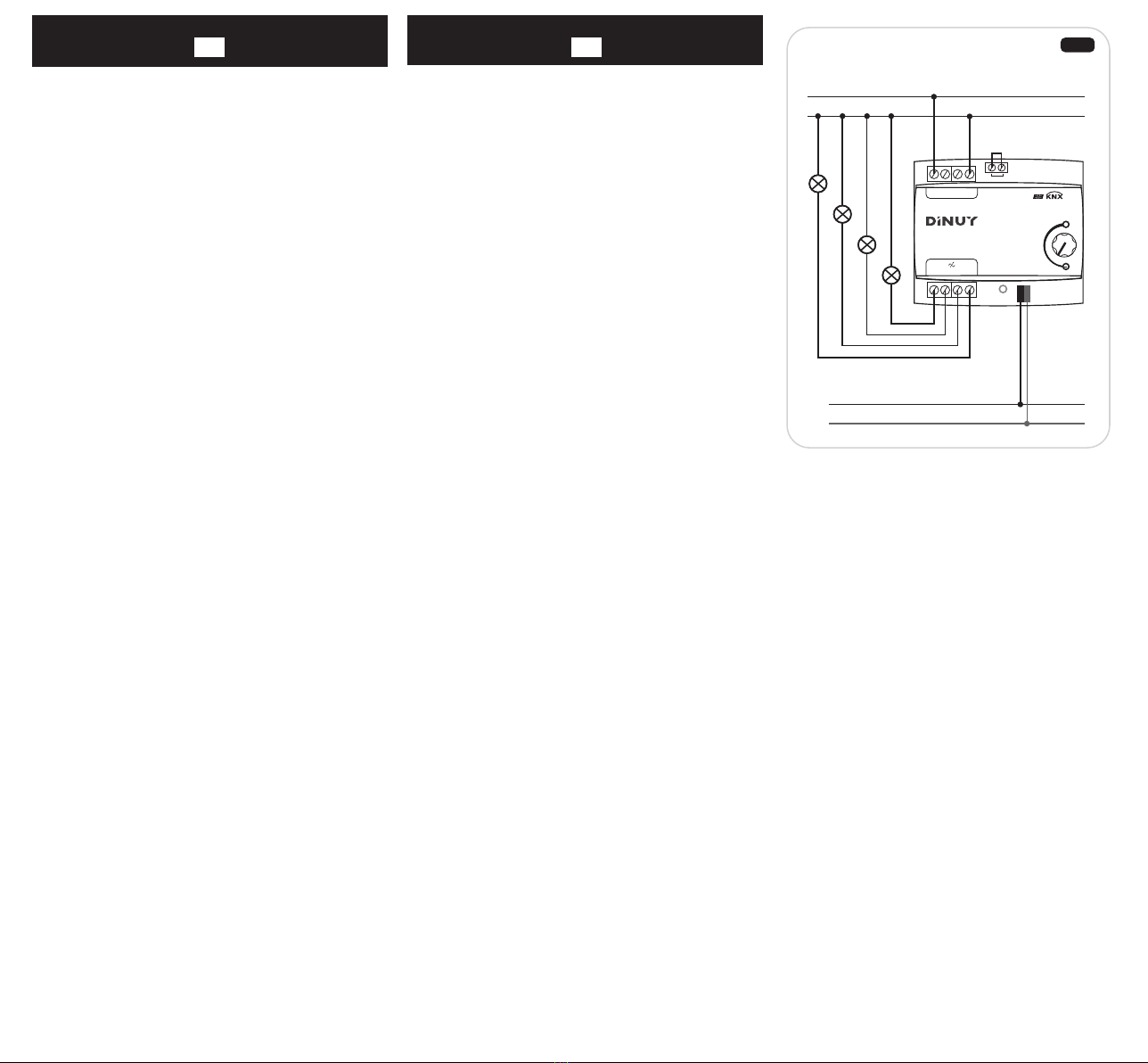
INSTALACIÓN Y CABLEADO
Siga los siguientes pasos para su instalación (Fig. 1):
1) Conecte el Bus KNX al terminal de conexión (C).
2) Conecte las lámparas al regulador.
3) Active la alimentación de red.
4) Active la alimentación del Bus KNX.
PUESTA EN MARCHA
1) Presione la tecla de programación (B). El LED se ilumina de forma permanente en
verde.
2) Programe la dirección física y la aplicación en el regulador desde el ETS.
3) El LED de programación (B) se apaga, indicando que la programación se ha realizado
correctamente y el actuador está listo para funcionar.
TECLA Y LED DE PROGRAMACIÓN (B)
Además de posibilitar la puesta en marcha del dispositivo, permite informar de un
problema de bloqueo del regulador, iluminándose de forma alterna en rojo y verde.
Esto sólo puede ser debido a una programación incorrecta desde el ETS.
En caso de darse esta situación, sería necesario Resetear el dispositivo,que consiste en
sacar la ficha del bus KNX (C), esperar un par de segundos y volver a conectar la ficha
KNX (C) mientras se tiene pulsada la tecla de programación (B). Además, tras este paso,
habría que volver a programarlo mediante el ETS.
PRECAUCIONES Y LIMITACIONES
· El suministro de red debe estar protegido de acuerdo a las normas vigentes.
· Los dispositivos deben ser instalados en ausencia de red y por personal cualificado.
· No conecte el suministro eléctrico si el regulador se encuentra en ausencia de carga (en
vacío).
· Desconecte la tensión de red para manipular la carga, al sustituir lámparas fundidas o al
quitarlas o añadirlas.
· No exceda la carga máxima del aparato.
· No mezcle distintos tipos de carga (capacitiva e inductiva).
· No instale los reguladores unos junto a los otros. Deje libre, al menos, un módulo de
distancia a los lados del regulador.
· Dimensione adecuadamente el armario de instalación para evitar problemas térmicos.
En algunos casos se podrá requerir ventilación forzada.
· El aparato puede bloquearse si actúan las protecciones de sobrecarga, cortocircuito o
térmica. Desconecte el suministro eléctrico, subsane la deficiencia y restablezca la red
para que el aparato vuelva a ser operativo.
L
N
230V~ 50Hz
-
+Bus KNX
Panic
RE KNT 004
4 x 230V~50Hz
L N
Made in EU
NL
MANUAL
AUTO
+
H 1.1 S 2.4
120214
17W39
4 x 10-250W
4 2 13
C1
C2
C3
C4
INSTALLATION AND WIRING
Follow these steps for installation (Fig. 1):
1) Connect the KNX bus to the connecting terminal (C).
2) Install the lamps to the dimmer.
3) Switch-on the mains supply.
4) Switch-on the bus supply.
COMMISSIONING
1) Press the programming key (B). The programming LED lights up green.
2) Program the physical address and application into the dimmer with the ETS.
3) The programming LED goes out: the application has been loaded
successfully and the dimmer is ready for working.
PROGRAMMING KEY AND LED (B)
In addition to enabling putting the actuator into operation, it is also useful to inform about
a blocking problem of the dimmer, lighting alternately in red and green.
This can only be due to incorrect programming from ETS.
In case of this problem, it would be necessary to reset the device, which consists of
removing the terminal (C) from the KNX bus, waiting a couple of seconds and
reconnecting the KNX terminal (C) while the programming key (B) is being pressed.
Moreover, after this step, it should be reprogrammed by the ETS.
CAUTIONS AND LIMITATIONS
· The mains supply must be protected according to existing rules.
· The devices must be installed without power supply and by qualified personnel.
· Do not apply power if the dimmer is without load.
· Disconnect the mains to handle the load, replacing burned-out lightbulbs, removing or
adding new ones.
· Do not exceed the maximum load of the device.
· Do not install dimmers next to each other. Leave free at least one module gap between
them or other sources of heat.
· Design the installation cabinet properly to avoid heat problems. In some cases may
require forced ventilation.
· The device may block if the overload, short-circuit or thermal protection are activated.
Disconnect the electrical supply, correct the fault and restore the supply in order that the
device returns to be operative.
E
GB Fig. 1
Other DINUY Controllers manuals


Popular Controllers manuals by other brands

Newport
Newport New Focus Picomotor 8742 user manual

Zamel
Zamel ROB-01 manual

RMG
RMG DFAWLC-044 installation manual

Siemens
Siemens IP Controller N350E Technical product information

Honeywell
Honeywell Aquasat L7224 A Aquasat L7224 C manual

Stealth Products
Stealth Products i-Drive 4.0 User's manual and maintenance guide


