Installation Instructions for Accu-Drain
INTRODUCTION
The Accu-Drain line is designed for trouble-free draining of
unwanted accumulations of condensation and other
foreign matter from any collection point in a compressed air
system. As the water level in the reservoir reaches the top,
an internal oat signals the Posi-Valve (our proprietary
sliding gate valve) to open. The valve stays open until the
oat returns to the bottom.
INSTALLATION
CAUTION: COMPRESSED AIR CAN BE DANGEROUS.
Before attempting to install the drain, be certain that the
pressure vessel on which the drain will be installed is
completely depressurized. If necessary, shut down the
compressor system and vent the pressure or activate the
bypass valve in your system to redirect air away from the
vessel the drain is being installed on.
The drain should not be installed in areas that are exposed
to freezing temperatures. Be certain that the air system
pressure does not exceed the 200 PSI working pressure of
the drain.
Connecting the drain to the air system should be done by
using one of the recommended installation diagrams
shown herein. The installation of a strainer is not required
or recommended.
Install the drain as close to the source to be drained as
possible. Since the Accu-Drain uses gravity to ll the
reservoir, the entire drain must be installed below the
vessel to be drained when using the top inlet. If exible
tubing is used on the discharge, be certain it is properly
fastened to prevent it from whipping when the drain
discharges the condensation.
The Accu-Drain 2 only has a top inlet. The additional port
in the bottom is a cleaning port and is not to be used for an
inlet. An optional vent port is included in the top of the drain
which comes plugged with a Phillips head screw. We
recommend removing the screw and installing the included
1/8” Push to Connect Fitting or any needle vent with a 10-
32 thread and plumbing that port into the vessel being
drained or in the system before the vessel being drained at
an equal or lower pressure.
The Accu-Drain 3 and 5 will accept condensation from
either the top or the bottom inlet of the reservoir. Where
possible, we recommend the condensation enter through
the bottom and a vent line be installed in the top inlet port.
The other end of the vent line should be installed at a point
in the system before the vessel being drained and at a
equal or lower pressure. This will ensure that the air in the
reservoir will properly exit as the condensation lls the tank
and replaces the air.
If the top inlet is used, the bottom inlet must be plugged
with a 1/2" NPT plug (not provided). In addition, the drain
should be installed as close to the source being drained as
possible. Any reduction in pipe size is not recommended.
When using the top inlet, the Accu-Drain reservoir cannot
be higher than the bottom of the vessel that is being
drained.
Verify the voltage on label of the drain and apply power to
the drain. Push the test button on the drain and conrm
that you hear the valve clicking.
Close the By-Pass drain valve and open the Shut-O valve.
The pressure vessel can now be repressurized.
CHECKING THE DRAIN'S OPERATION
Testing the Accu-Drain can be done by pushing the TEST
button.
After installation is complete and the drain is online, a
check should be made that the condensation is properly
entering the reservoir. This can easily be done by looking
through the transparent reservoir.
If condensation is not entering the reservoir, check for the
following:
Push the test button on the control panel to see if any
condensation is drawn into the reservoir. If condensation is
drawn in, then check items 2, 3, and 4. If no condensation
is drawn in check items 1, and 5.
1. Make sure the auxiliary shut o valve is open.
2. Do not use the bottom inlet on the Accu-Drain
without installing a vent line (above the water line.)
3. If a vent line is installed, make sure that it is at or
upstream from the vessel that is being drained.
4. Be certain that the Accu-Drain reservoir is not higher
than the vessel that is being drained. This is very
important when using the top inlet on the Accu-Drain
reservoir.
5. Check to make sure that the vessel being drained has
condensation in it.
If the top inlet is being used and no condensation is
entering the Accu-Drain 3 or 5 reservoir, and all the above
items have been checked, then we recommend that the
bottom inlet be used with a vent line out of the top.
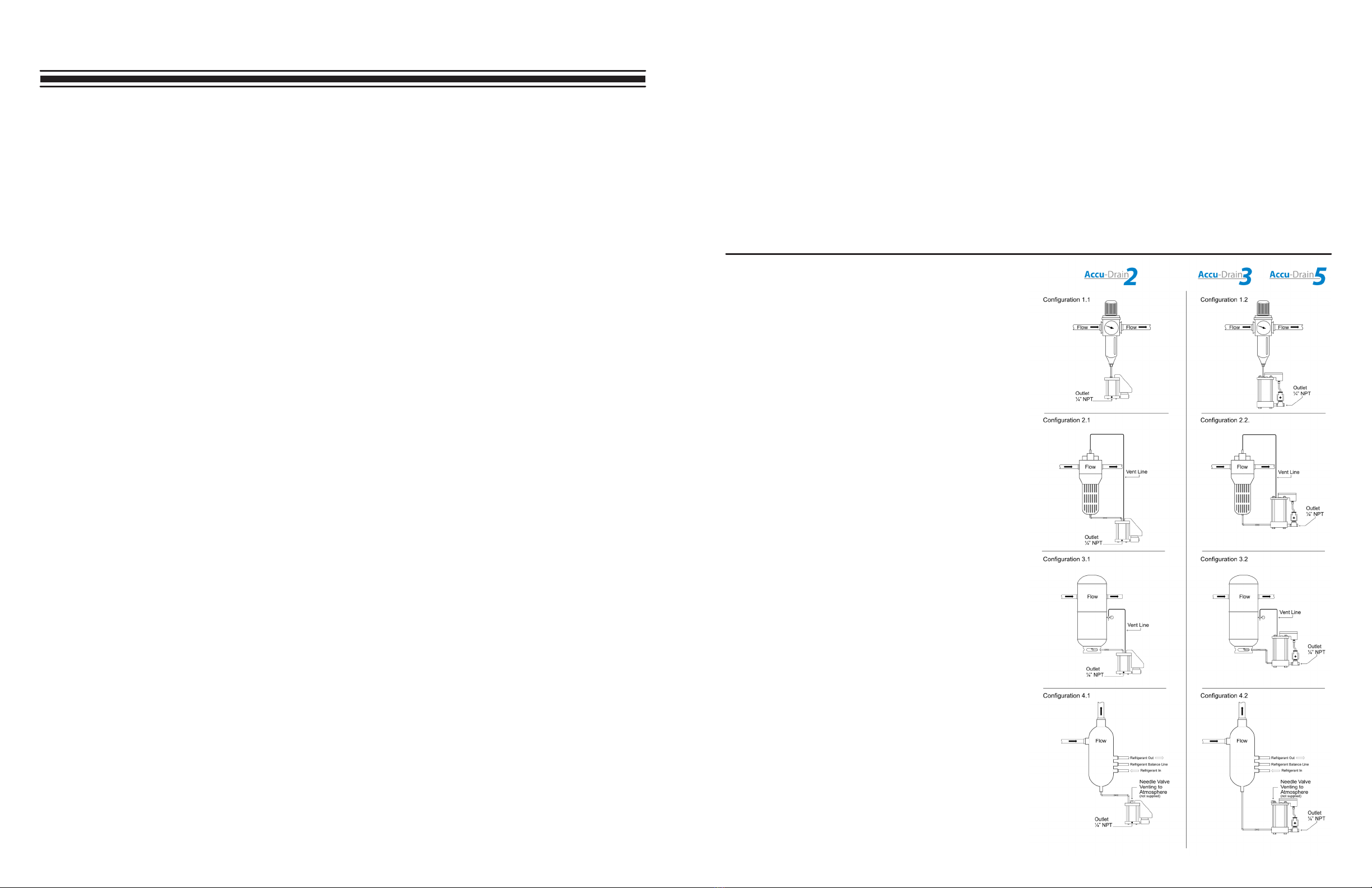
APPLICATIONS
Conguration 1.1 & 1.2
Prelters, Coalescing lters, Moisture Separators, Drip
Legs.
Conguration 2.1 & 2.2
Large Prelters, Coalescing lters, Moisture Separators.
Conguration 3.1 & 3.2
Air Receiver Tanks.
Conguration 4.1 & 4.2
Refrigerated Air Dryers. This is the preferred method of
installation when it is not possible to return the vent line
back to the vessel being drained on Refrigerated Air
Dryers.
This method prevents reintroducing water vapor back into
the dried air stream which would elevate the pressure
dewpoint. (See Note below.)
NOTE:
When opting to use Alternative Installation Method #4, it is
necessary to adjust the “bleed” rate. The object here is to
allow a small amount of compressed air to bleed through
the Needle valve to atmosphere. This allows the
condensate to enter the Accu-Drain without “air-locking”
the reservoir. The following procedure applies when
adjusting the “bleed” rate for Drawing #4.
1. Close the needle valve. Then pressure Accu-Drain.
2. Slowly open needle valve until you can feel air exiting.
3. When the water level is visible, adjust the needle
valve to control the bleed rate. Slowly open or close
the needle valve until you see the water line ripple as
the air breaks through.
4. A small amount of air exiting the needle valve veries
proper adjustment.
IN GENERAL
ACCU-DRAIN relies on gravity to ll its reservoir. In order
for the condensate to properly enter the Accu-Drain
reservoir, it must be installed at a point lower than the
bottom of the vessel to be drained. Attempt to keep the
piping run short, while positioning the Accu-Drain as close
as possible to the drainage point. Run the piping in a
continuously sloping manner while avoiding any pockets
where condensate might collect. Always use non-galling
pipe sealant. The use of unions and shut-o valves are
recommended wherever possible.
VENTING / BALANCE LINE
Allowing the air to exit the Accu-Drain’s reservoir as the
condensate enters is critical for proper operation. The unit
will “air-lock” and not work properly if that exchange
cannot take place. Installing a balance line is often
necessary when it is not possible to adapt the Accu-Drain
directly to the vessel. It may also be required when sudden
surges of condensate are heavy enough to “airlock” the
Accu-Drain’s reservoir. Connecting the balance line back
to a point in the system where the pressure is “equal-to or
lesser than” the drain point will allow the condensate to ll
the reservoir while eliminating the possibility of an “air-
lock” condition.


