STEP 1)
Place blower in a clean fresh air environment. Set blower a minimum of 5 ft. from the man-
hole opening. Note: Inspect blower for damaged or worn parts. Inspect all ducting
and couplings for possible air leaks prior to blower operation.
Note: Air quality of the conned space should be tested prior to ventilation. If air
quality of the conned space is unacceptable, consult a trained professional.
STEP 2)
Install duct cuff to exhaust ange and tighten cinch strap. Keep bends and kinks in ducting
to a minimum to maximize air ow.
NOTE: The use of conductive ducting is recommended when operating in potentially
explosive environments. Assure that the blower is properly grounded before oper-
ating and the ground wire in the conductive ducting is attached to the blower and
Saddle Vent®, if used.
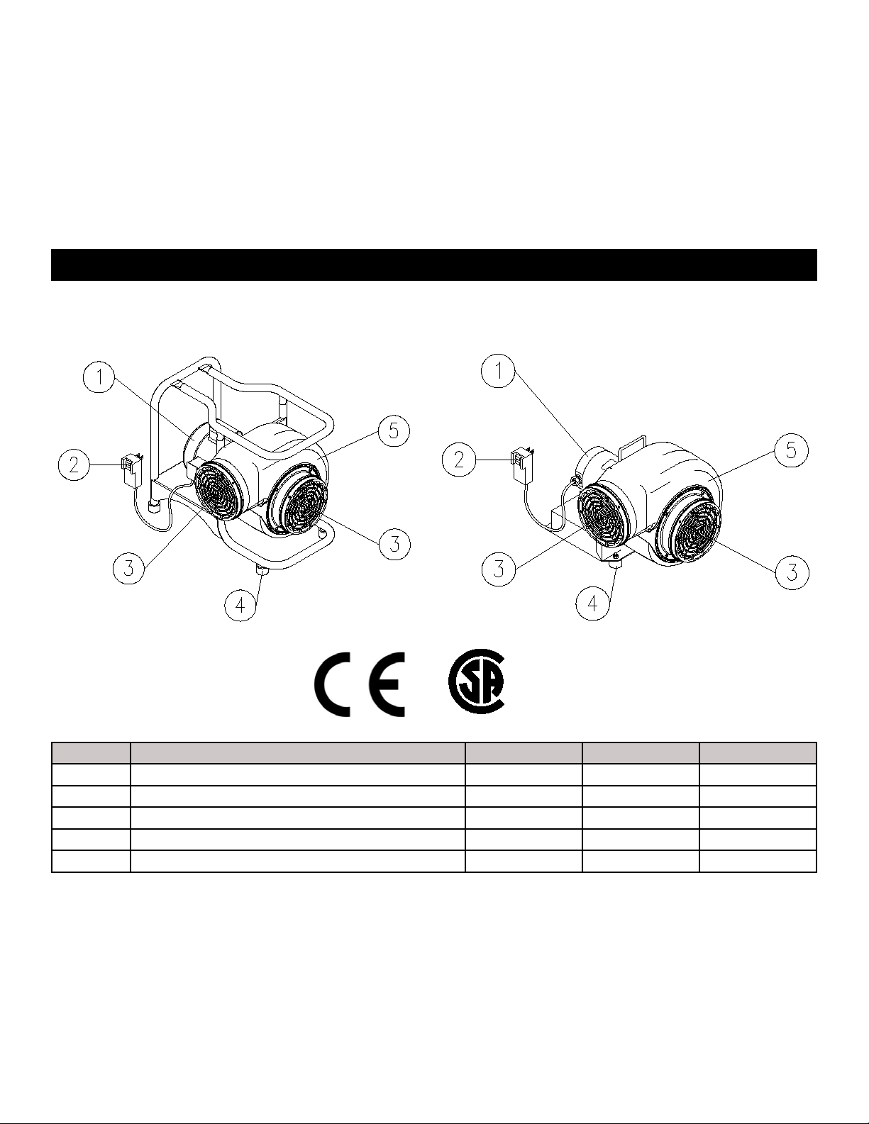
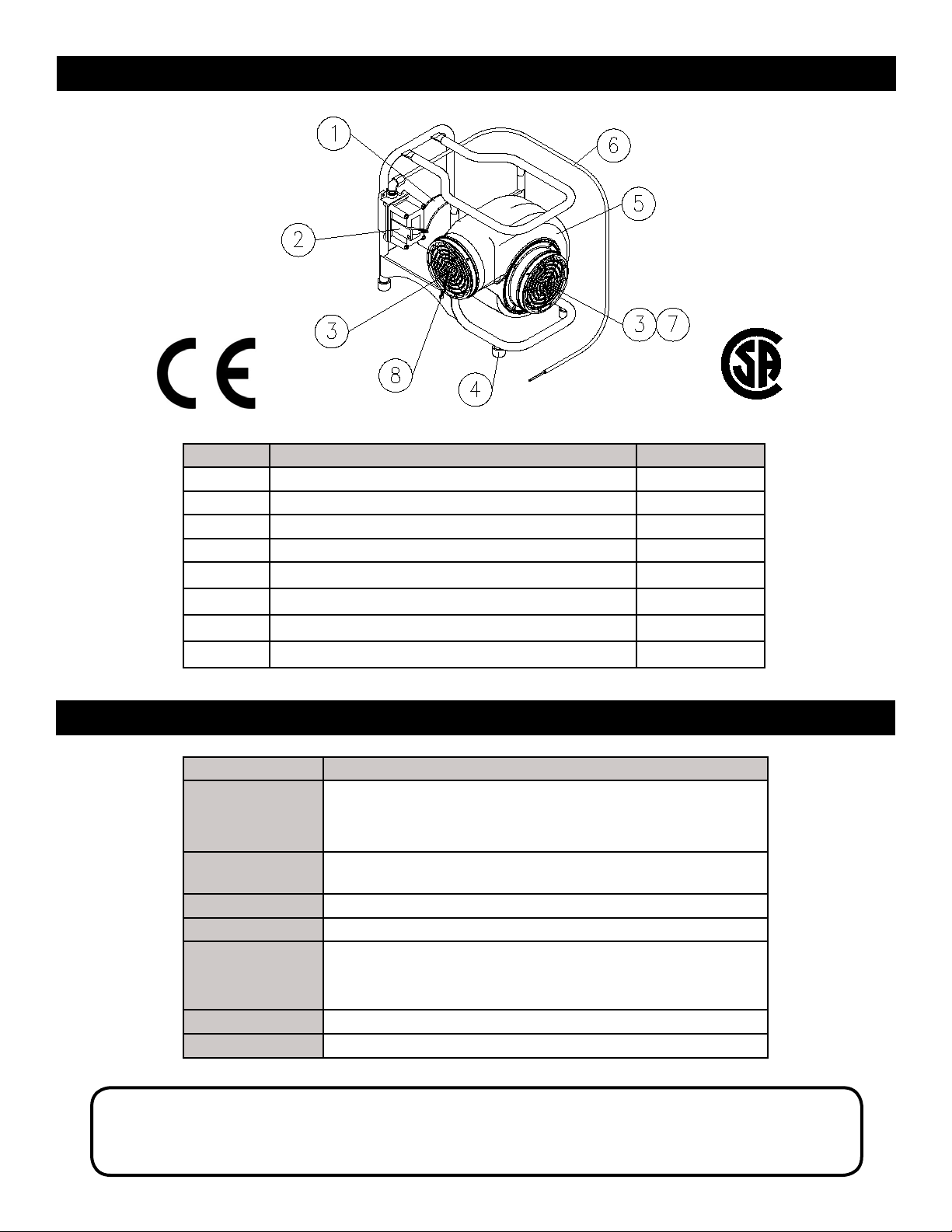
Grounding lug provided for
ground wire attachment from
conductive duct.
STEP 3)
Explosion-proof models should be tted with an approved explosion-proof plug to meet Class 1, Div. 1, Groups C and D,
Class II, Div. I, Groups E, F, G specications. The plug should not be disconnected or connected in an explosive environ–
ment when the blower is energized.
STEP 4)
Switch the explosion-proof “ON/OFF” switch to the “ON” position. The unit is now operational.
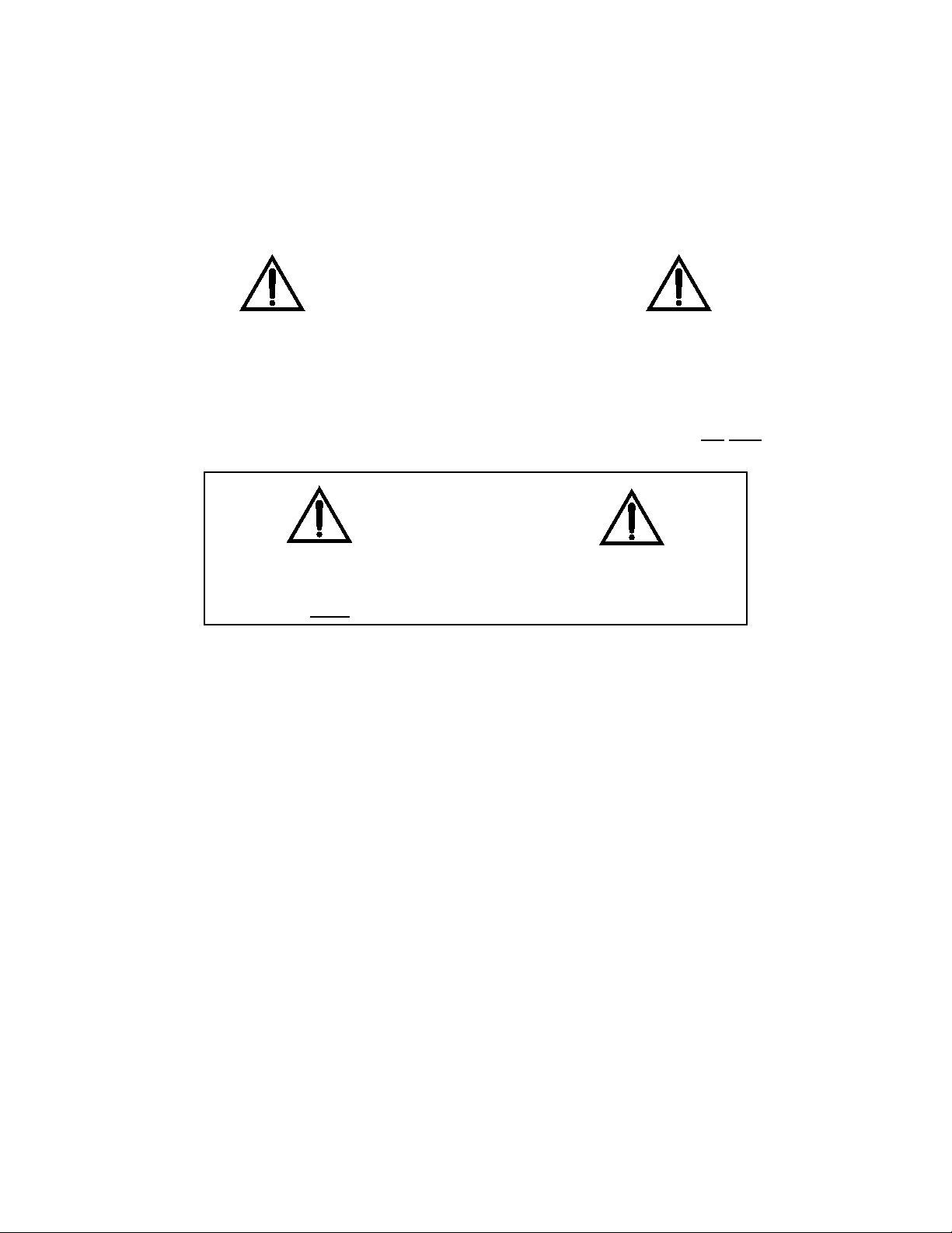
CAUTION:
If explosive or volatile vapors are suspected or present, follow ANSI/API
procedure 2015 and 2016 for proper grounding of the blower. All static
electricity must be removed from the blower and attached ducting prior to
energizing the blower. Conductive ducting should be tested semi-annually
to assure resistance (ohms) does not exceed 300k. If sufcient resistance is
not achieved, the duct should be removed from service.
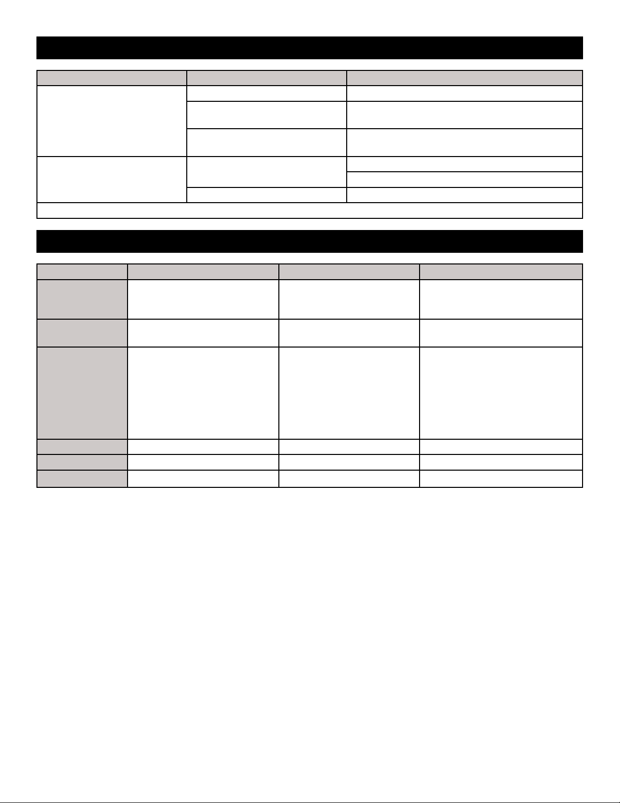
PROBLEM POSSIBLE CAUSE SOLUTION
Excessive vibration
Air intake blocked Turn blower off and clear debris from intake.
Possible internal damage Turn blower off and inspect fan blades, shaft, and
housing for debris, damage, and loose screws.
Possible external damage Turn blower off and inspect blower housing and
frame.
Blower will not start Circuit breaker trips Wattage output of power source insufcient*
Extension cord improperly sized
Faulty wall outlet Test voltage with meter.
7
Troubleshooting
General Setup & Operation
Model: SVB-E8EXP