AIR SYSTEMS HP-A4K User manual

AIR SYSTEMS INTERNATIONAL, INC.
829 Juniper Crescent, Chesapeake, Va, 23320
Telephone (757) 424-3967
Toll Free 1-800-866-8100
Fax No. (757) 424-5348
http://www.airsystems.com
e-mail: [email protected]
Air Quality Test Kits
Models: LP/HP-A4K and LP/HP-A445K
OPERATING INSTRUCTIONS AND REPLACEMENT PARTS

2
Air Systems’ breathing air quality test kits are designed to test are designed to test the air produced by compressors
and compressed air in cylinders. These tests are accomplished through the use of detector tubes that provide a “go/no go”
test of the air quality. If a high reading is found, this signals the user that they have a potentially unacceptable quality of
breathing air. If this occurs, a laboratory analysis of the air components must be made to determine the exact readings of
the air quality and take corrective action. For precision laboratory analysis, contact Air Systems’ customer service depart-
ment, 1-800-866-8100.
Federal OSHA requires that Grade-D air be supplied to the respirator user. OSHA’s air quality standards are found in
Section 29CFR 1910.134(i) in the Code of Federal Regulations. OSHA’s standards are taken from the Compressed Gas
Association (CGA) Commodity Specication G-7.1 - 1989. CGA’s standard for Grade-D air is as follows:
Carbon Dioxide: 1000 ppm maximum
Carbon Monoxide: 10 ppm maximum
Oil Mist: 5.0 mg/m3(Condensed Hydrocarbons)
Water Vapor: 30-80 mg/m3(Cylinder air only)
Our test kits use the above test tubes as standard, other test tubes are available for specic tests of suspected con-
taminants. Call us for your specic aplications.
Oxygen tests are available from our oxygen test meter, Model AQT-O2. Consult factory for details.
Overview

3
Low Pressure Air Tests - 125 PSI Maximum
Procedure for Model LP-A4
STEP 5)
At the end of each test period, read the tube immediately and record the results. Repeat with the other tubes until all de-
sired contaminants have been sampled.
STEP 6)
Close the regulator knob (turn counterclockwise) to shut off pressure to owmeter. Open the owmeter valve to bleed
pressure from the owmeter. Disconnect regulator from air distribution manifold and store system in case.
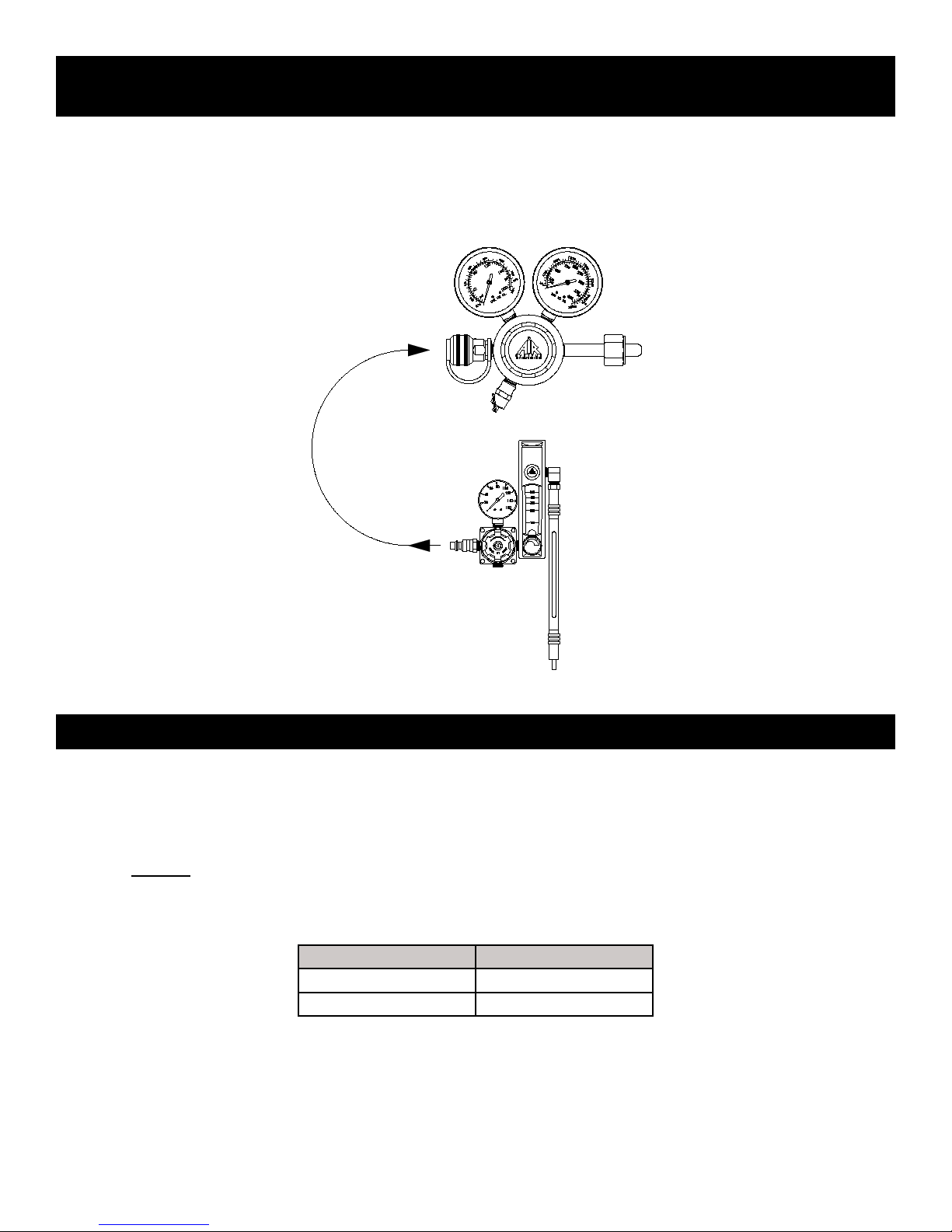
Model LP-A4 is supplied with a regulator/owmeter that must be con-
nected after the compressor’s Grade-D ltration system. The male plug,
1/4” industrial interchange, installed on the inlet of the pressure regulator
can be coupled directly into the air distribution manifold of the ltration
system. The test will determine acceptable air quality and whether or not
the ltration system is functioning properly.
STEP 1)
Attach regulator assembly to female coupling on air distribution manifold.
The owmeter should be in the vertical position for maximum accuracy.
NOTE: The 1/4” industrial interchange plug on the regulator will need to
be changed or an adapter used if the coupling on the manifold is some-
thing other than a 1/4” industrial interchange.
STEP 2)
Turn the regulator knob clockwise and set pressure between 20-30 PSI.
Do not adjust the owmeter at this time.
NOTE: The recommended tube testing sequence is as follows:
water vapor, carbon dioxide, carbon monoxide, and oil mist.
STEP 3)
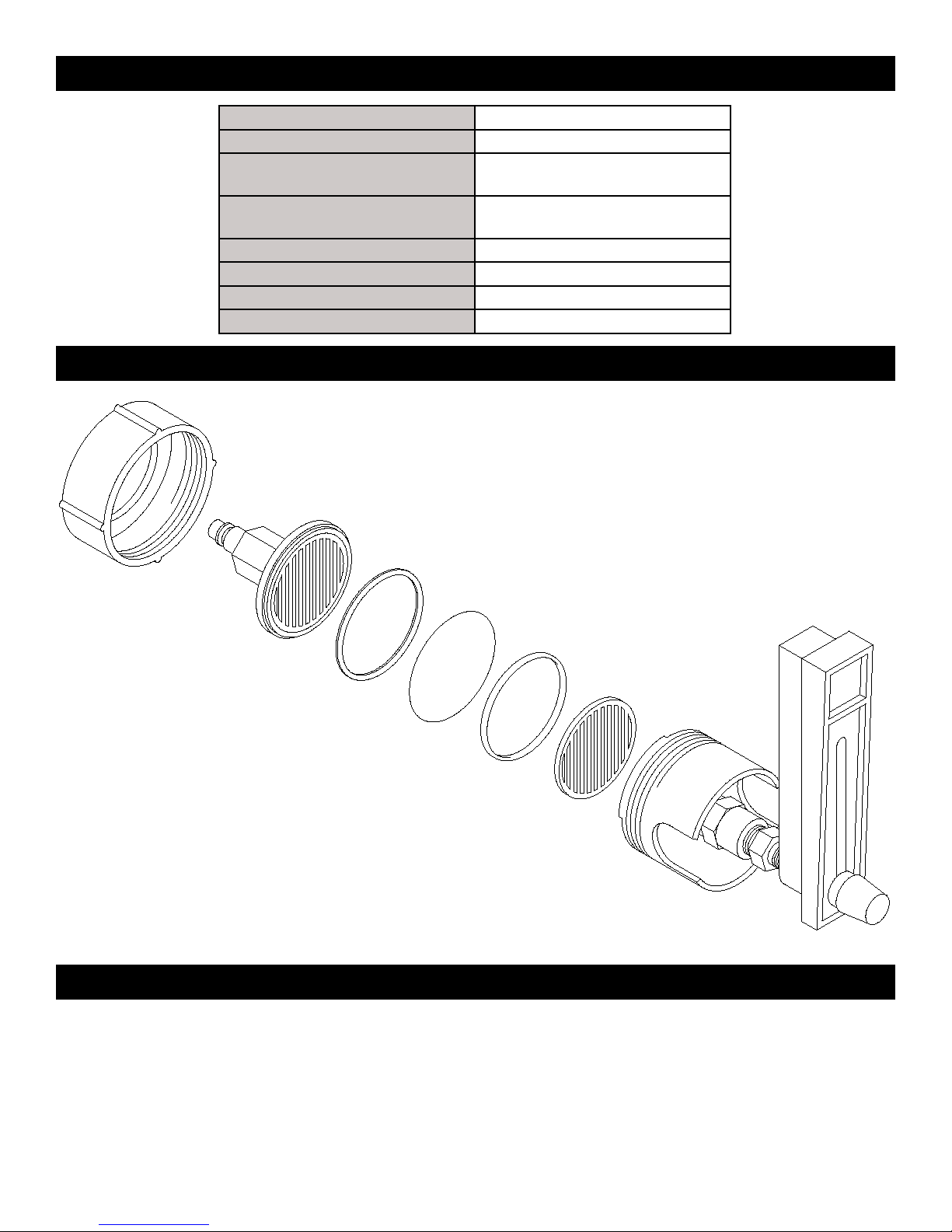
Break the ends off a fresh test tube using the small metal breaker sleeve
in the kit. Install the test tube in the rubber tube holder with the directional
arrow found on the tube pointing down. Install tube by rst inserting the
upper end into the holder then stretching the holder over the lower
STEP 4)
The rubber tube holder is then inserted into the hose barb with the test
tube arrow pointing down. Adjust the owmeter to the ow rate per the
chart on the following page and the required time. Start the test with the
water vapor test tube and work through the chart. Test Tube Breaker Sleeve
Test Tube Holder
Flowmeter
Regulator
1/4” Male Plug
Tube Contaminant Flow Rate CC/Min Test Time In Minutes
Gastec Sensidyne Gastec Sensidyne Gastec Sensidyne
6A 603SPA Water Vapor 100 500 10 1.4
2A 601SP Carbon Dioxide 100 100 5 3.5
1A 6005P Carbon Monoxide 100 175 3 2
109AD 6025P Oil Mist 500 470 40 25
WARNING!
Do not attempt to remove regulator while system is pressurized. Always test air quality after the lter system to assure
proper function. The periodic testing of CO levels does not substitute for a CO or high temperature alarm per OSHA reg-
ulations. We recommend the installation of a CO monitor in the breathing air system to continuously monitor for CO. Call
Air Systems’ customer service department to discuss a retrot for your system.

High Pressure Air Cylinder Tests
Procedure for Models: HP-A4 and HP-A445
Select the proper test module based on the pressure of the cylinder to be tested (HP-A4 up to 3000 PSI and HP-A445
up to 5000 PSI. A dual stage high pressure regulator is provided to reduce cylinder pressure before it is delivered to the
owmeter. The CGA-346 or 347 wrench tight nut/stem is attached to the cylinder valve. The output pressure to the ow-
meter is set between 20-30 PSI. Attach the test module, Model LP-A4 to the female coupling on the regulator and follow
steps 1 thru 6 on the previous page.
Detector Tube Reading and Interpretaon
The following information will be helpful when reading and interpreting the detector tubes.
A. Always read the tubes and record the results immediately after testing. In some cases stains may fade or crawl within
a few hours.
B. A tube may not be reused; even after a zero reading.
C. The oil mist is normally used at 500 cc/min for 2 hours, however, reliable results are obtained using shorter sampling
periods and correcting the reading with a multiplication factor as indicated below.
Test Duration Multiply Reading By
30 Minutes 4
60 Minutes 2
D. If at the end of a test it is noted that the stain has overshot the scale, the actual concentration may be determined as
follows; repeat the test with a new tube and observe the time required to reach the highest calibration mark (full scale).
Multiply the full scale concentration by the ratio of recommended test time to actual test time.
Example: The H2O tube reaches full scale (80 mg/m3) in six minutes.
80 x 106 = 133 mg/m3(actual concentration).
4

High moisture content, usually above 250 mg/m3, will result in unreliable readings in the oil mist tube. To remove ex-
cessive moisture from the breathing air line, prior to running the moisture test tube, order Air System’s prelter assembly
P/N FLTR020. Attach the lter to the male inlet plug located on the LP-A4 test module before performing the air test. An
approximate 10% correction factor should be added to the oil tube reading to achieve a more accurate reading.
Enclosed in the kit is a data sheet to allow you to send your lter sample to Trace Analytics if you would like an inde-
pendent laboratory to provide the weighing service for your lter. To obtain more information, contact Trace Analytics at
1-800-247-1024.
The module has been designed for quick, accurate tests of total particulates and oil mist found in breathing air. One
cubic meter of air is passed over a pre-weighted lter with the resulting difference in weight equaling the total particulate
and oil found in the tested breathing air.
The LP-47PF test module is plugged directly into the output air coupling after the Grade-D lter system or into the
pressure reducing regulator used for bottled air testing. Maximum pressure should not exceed 20 PSI coming into the
test module. The polycarbonate test module holds the pre-weighted lter. The other end has a 1/4” plug attached which is
plugged into the air outlet coupling of the breathing air system. After testing, the lter is weighed to check lter weight and
a calculation is made in mg/m3.
Using the steel forceps supplied in the kit, install a 47mm pre-weighted lter in the polycarbonate lter holder. With the
lters installed, plug the test module into the air outlet tting, not exceeding 20 PSI. Adjust the ow to 50 LPM and allow
the air to ow for 20 minutes. This results in 1 cubic meter of air being passed over the lters. If a different time is used
it should be noted. After 20 minutes, the air is turned off at the regulator, the lter is removed from the housing using the
forceps and placed in the supplied petri dish. The tested lter sample should be sent to a laboratory for weighing on a
microbalance scale.
Detector Tube Reading and Interpretaon
Special Applicaon For High Moisture Environment
Total Parculate/Oil Mist Test Procedure For Model LP-47PF
Laboratory Services Available
First H2O (Water)
Second CO2 (Carbon Dioxide)
Third CO (Carbon Monoxide)
Fourth Oil Mist
E. Excessive water vapor (i.e. greater than 250 mg/m3 H2O) may cause the oil mist tube (#109-AD) to become unrelia-
ble. Run the water vapor test before running the oil mist test to determine the water vapor level. The recommended
testing sequence is shown below:
F. Always use the enclosed quick connect valve to ush the system before putting the lter holder in-line for analysis.
Flushing or purging should continue at 2-3 minutes until no visible water is discharged from the line.
G. Never exceed 20 PSI into the lter holder otherwise damage to the assembly may occur.
H. Always record the ow rate and run time on the petri dish lter holder when returning the unit for weighing.
I. Never touch the lter membranes as the results could be contaminated.
5
This manual suits for next models
3
Table of contents
Popular Test Equipment manuals by other brands

Redtech
Redtech TRAILERteck T05 user manual

Venmar
Venmar AVS Constructo 1.0 HRV user guide

Test Instrument Solutions
Test Instrument Solutions SafetyPAT operating manual

Hanna Instruments
Hanna Instruments HI 38078 instruction manual

Kistler
Kistler 5495C Series instruction manual

Waygate Technologies
Waygate Technologies DM5E Basic quick start guide

StoneL
StoneL DeviceNet CK464002A manual

Seica
Seica RAPID 220 Site preparation guide

Kingfisher
Kingfisher KI7400 Series Training manual

Kurth Electronic
Kurth Electronic CCTS-03 operating manual

SMART
SMART KANAAD SBT XTREME 3G Series user manual

Agilent Technologies
Agilent Technologies BERT Serial Getting started