Air Weigh QuickLoad User manual

1
PN 901-0144-002 R0
Air-Weigh Customer Support: 888-459-3247
QuickLoad
Installation Guide
Mack Camelback Suspensions
Welded Drive Brackets

2
Table of Contents
Scale Overview.................................................................................1
Overview: Sensor Installation......................................................1
Tools Required.................................................................................2
Installing the Sensor Bracket on the Camelback Suspension...3
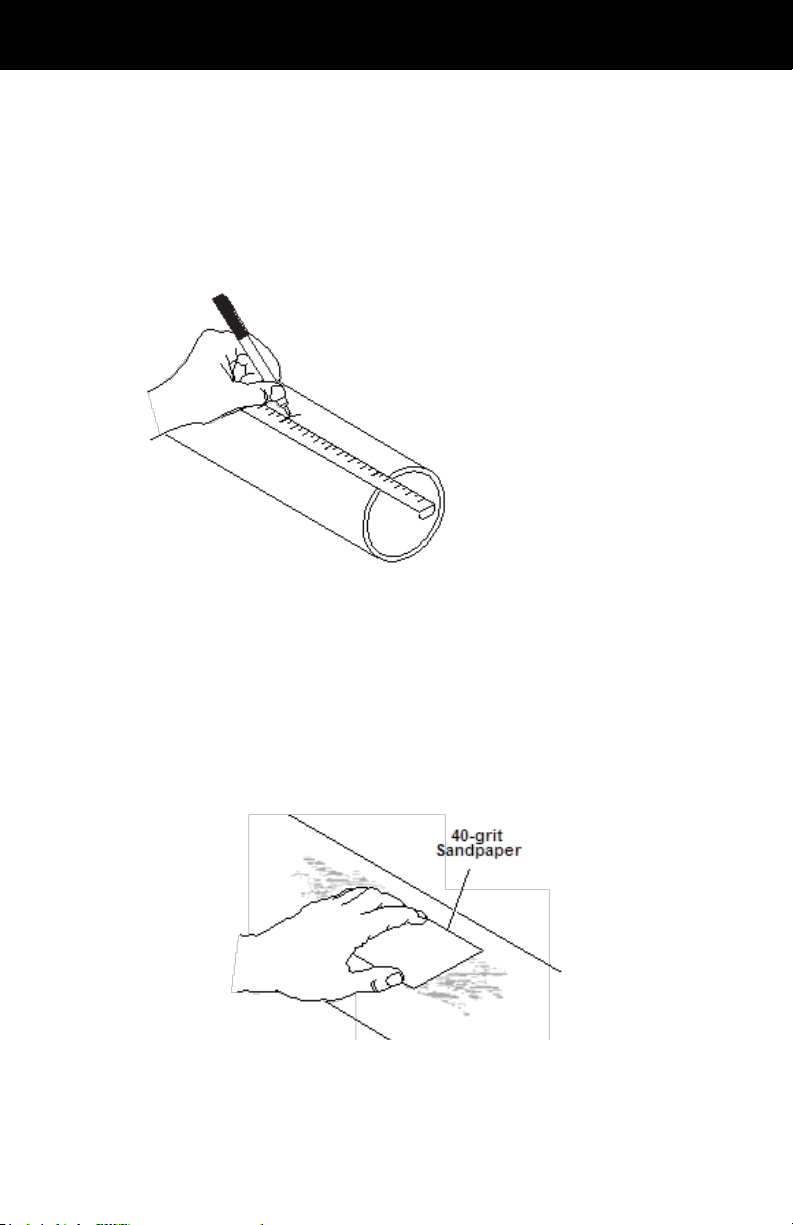
Preparing the Camelback Suspension......................................3
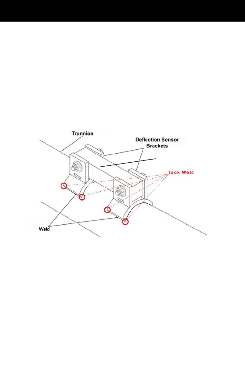
Welding the Bracket......................................................................4
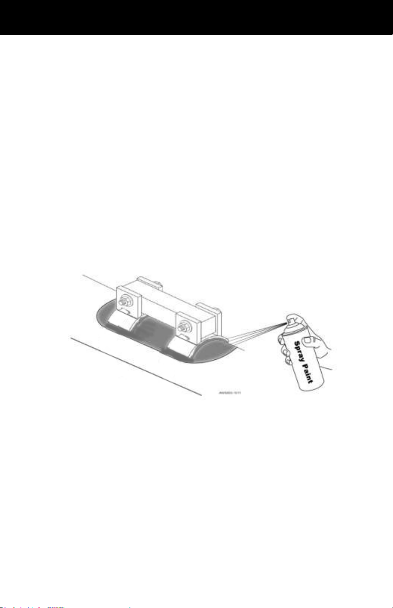
Adding a Protective Spray Paint Coating..................................5
Installing the Display and Cables..................................................6
Routing the Sensor Extension Cable.........................................6
Preparing the Cab Display for Installation.................................7
Installing the Cab Display.............................................................7
Securing Cables and Reassembling the Dash........................9
Setting the Sensor A/D Values.................................................10
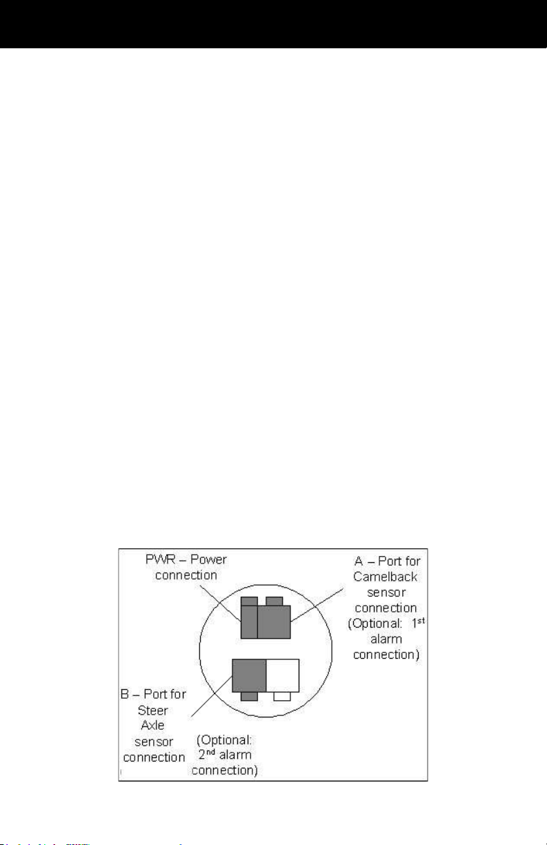
Assembling the Electrical Connector.......................................10
Adjusting the A/D Reading.........................................................11
Final Sensor Torque....................................................................12
Cover Installation...........................................................................13
Notes................................................................................................15
Limited Warranty............................................................................16
Procedure for Warranty Claims....................................................17

1
Scale Overview
The Air-Weigh QuickLoad Scale for vocational vehicles with the
Mack Camelback suspension includes a dashboard-mounted
mounting hardware for the Camelback suspension, and sensor
cables.
This Installation Guide provides all the instructions needed to install
Follow the installing procedures in this guide exactly for the most
accurate weighing.
The User Guide, included with the scale kit, provides the complete
scale calibration and operation procedures.
Overview: Sensor Installation
The following overview steps are to be applied to the Camelback
Suspension Sensor Installation:
• Mark the center of the trunnion tube.
• Mount bracket assembly on the trunnion tube.
• Connect the cables
•
it to the QuickLoad Scale Sensor Port A.
• Mount the sensor to the bracket.
• Check for sensor readings in range.
• Mount the cover over the sensor and brackets.

2
Tools Required
The list below contains the tools (customer supplied) to properly
• Sander/grinder
• 40-grit medium sandpaper
• Chalk or permanent marker
• 22mm combination wrench
• Torque wrench, 20 – 120 ft-lb
• 22mm socket and 3/8-inch socket handle
• Enamel spray paint
• Tape measure
• C clamps
• ARC or MIG welder
•
Note: Heavy calibration must be done using maximum vehicle
loads. See QuickLoad Calibrations and Operations manual, for
additional information on calibration.
Cables to the sensor, and any other Air-Weigh wiring, must be
separated by a minimum of 12 inches, or properly shielded, from
exhaust piping.
Do not move vehicle until the alignment tool is removed.
Do not calibrate sensor following installation until the vehicle has
been in operation for one week or 800 miles, whichever comes

3
Installing the Sensor Bracket on the
Camelback Suspension
Preparing the Camelback Suspension
Sanding the Trunnion Tube
Marking Center of Trunnion Tube
2. Using chalk or permanent marker, mark the top of the
trunnion tube 3-3/8 in. (85.725mm) on both sides of the
center mark. The overall measurement is 6-3/4 in. (171.45
mm).
3. Using a grinder or 40-grit medium sandpaper, sand the
marked off area until it is free of paint and other residues.
4. Clean the sanded area.
5. Re-mark the center of the trunnion tube.

4
Welding the Bracket
1. Place the mounting bracket assembly on the top center of
the trunnion tube. Mark the center on the alignment tool and
ensure it lines up with the center mark on the trunnion tube.
2. Use C clamps to hold the bracket in place. Make sure you
leave the alignment tool in the bracket assembly while
welding.
Placing the Brackets on the Trunnion Tube
3. Tack weld all 8 corners of the base of the bracket.
4. Fillet weld a full bead on the edges of each bracket piece.
5. Allow the weld and the bracket to completely cool.
Alignment Tool

5
Adding a Protective Spray Paint Coating
1. To prevent the drive axle bracket from delaminating due to
corrosion, we recommend you spray paint around the base of
the brackets.
2. Using any enamel-based spray paint, paint around the
base of the bracket. Paint all bare metal around the bracket
completely.
3. Once the paint is dry, we recommend that you paint all
exposed metal a second time.
Spray Painting the Bracket

6
Installing the Display and Cables
Routing the Sensor Extension Cable
1. Starting from where you mounted the bracket, route the drive
axle extension cable along the axle and the frame, and then
display on the dash. If possible, route along an existing wire
harness. Be careful to avoid routing along pieces of the
frame that may move or cause wiring to rub.
2. The drive axle sensor extension cable will be connected to
Sensor Port A on the back of the QuickLoad display once the
display is installed.
3. Coil and secure the drive axle extension cable approximately
every foot along the frame of the truck using zip ties. Leave
the ties loosely attached, as you will tighten them later in the
install process.
Note: Keep all cables a minimum of 12” from exhaust piping or
properly shield cables.
Drive Axle Connections

7
Preparing the Cab Display for Installation
The Optional Universal Mounting Pod can be used for installations
where there is no space in the dash to mount the scale display.
1. Select a location for the display (1) on the dash panel (5) with
at least 3” of clearance behind the dash panel (5) for the unit
and its connections. A higher dash position provides better
visibility.
2. Using a hole saw, cut a 2-1/8” hole (2) in the dash where you
will mount the display.
3. Remove the hex nuts (4) from the studs (6) on the back of the
display (1) to release the mounting bracket (3).
Installing the Cab Display
1. Position the display (1) in the hole so that it appears level on
the dash.
2. Reinstall the mounting bracket (3) on the back of the display
(1) and secure with two nuts (4) on the display studs (6).
Tighten the nuts (4) and secure the display (1) to the dash
using 6 in-lbs. of torque. Do not over- tighten the mounting
bracket nuts (4).
3. Connect the drive axle extension cable to the display in the
dash to Port A.
Display Preparation and Installation

8
extending toward the side of the vehicle where you routed the
on the sensor should face up.
Inserting the Sensor
3. Slide the bolt through the bracket holes so that the bolthead
is secured in the manufactured bolthead holder.
Inserting Bolt and Washers into Sensor and Bracket

9
Securing Cables and Reassembling the Dash
1. Coil and secure any excess wire using zip ties.
2. Tighten all zip ties and trim.
3. Reassemble the dash assembly after the sensor has been
installed and sensor cables are connected. Ensure all
connections are tight.

10
Setting the A/D values
At this point, you have installed all of the QuickLoad system
weight correctly by setting its A/D values. A/D refers to the analog-
to-digital conversion of the sensor reading.
This step will require the use of either the QuickLoad Scale or the
Sensor Extension Cable must be installed.
Assembling the Electrical Connector
1.
connector plug into the sensor extension cable connector OR
the locking tabs on the connector plug engage completely.
Assembling the Electrical Connector
Note: When tightening the bolts, ALWAYS torque the nut, NOT the
bolt head. The bolt head should be in the bolt head holder, which is
built into the bracket.

11
2. Tighten both nuts and use a torque wrench to torque to 60
ft-lbs.
3. Verify the A/D reading using the display in the cab (start the
test box. If the reading is within range (750-1250), continue
to instructions for the Final Sensor Torque.If the reading
is not within range, follow the instructions to adjust the A/D
readings below.
Adjusting the A/D Reading
If the A/D reading is above 1250, follow these instructions:
1. Loosen the nuts on both ends of the sensor
2. At the plastic nut where the cable enters the sensor,
exert DOWNWARD
A/D reading is between 750 and 1250. Continue to apply
pressure to maintain the desired A/D reading during the
torque procedures in step 3.
3. Tighten the nut on the cable end of the sensor and torque to
60 ft/lbs.
the plastic nut during torquing in order to maintain the
desired A/D reading.If the A/D readings are still within the
750 to 1250 range after the nuts on both sides of the sensor
have been torque to 60 ft/lbs., continue to instructions for
the Final Sensor Torque.

12
If the A/D reading is below 750, or there is no A/D reading at all,
follow the steps below:
1. Loosen the nuts on both ends of the sensor
2. At the plastic nut where the cable enters the sensor, exert
UPWARD
is between 750 and 1250. Continue to apply pressure
to maintain the desired A/D reading during the torque
procedures in step 3.
3. Tighten the nut on the cable end of the sensor and torqued
to 60 ft/lbs.
to the plastic nut during torquing in order to maintain
the desired A/D reading.If the A/D readings are still
within the 750 to 1250 range after the nuts on both sides
of the sensor have been torqued to 60 ft/lbs., continue to
instructions for the Final Sensor Torque.
Final Sensor Torque
1. Torque both nuts to 120 ft/lbs.
2.
the in-cab QuickLoad display, not from the A/D Box. If A/D
readings are not within range, repeat the Adjusting the
A/D reading steps.

13
Cover Installation
1. Locate the opening in the end of the cover. The opening is
used for the sensor cable to go through.
Cable Opening in Cover
2. Cut a notch in the supplied grommet and place it on the
sensor cable.
Notching the Grommet

14
3. Slide the sensor cable/grommet combination into the cover
hole with the Molex connector of the sensor cable on the
over the sensor on the trunnion tube.
Placing the Cable and Grommet into Cover
cover and tighten in place.
Your Air-Weigh scale installation is now complete.
Clamping the Cover to the Trunnion Tube

15
Notes

16
Limited Warranty
For product failures due to material or manufacturing defects, Air-Weigh will
replace or repair all components for up to 3 years from shipment date to the
end-user Air-Weigh customer. These three-year components include: Displays,
ComLinks, Sensors, Power Cables, Sensor Assemblies, Sensor Harnesses, and
all other associated external components. Air-Weigh assumes no responsibility for
administering warranty claims directly with any third party end users.
The responsibility of Air-Weigh under this warranty is limited to the repair,
replacement, or credit of the defective part or assembly.
This warranty does not cover incidental or consequential damage to persons or
property caused by use, abuse, misuse, or failure to comply with installation or
operating instructions. This limited warranty does not apply to any product that
has failed due to accident, abuse, alteration, installation not consistent with printed
installation instructions, improper maintenance, improper operation, or as a result
of system integration or installation not explicitly approved in writing by Air-Weigh.
Air-Weigh and its resellers shall have no responsibility or liability for damages
if the purchaser or any other person alters the vehicle incorporating Air-Weigh
products. This limited warranty shall not apply to any product that has been
repaired or altered by anyone not employed by Air-Weigh or not operated in
accordance with the manufacturer’s printed material delivered with this product.
Air-Weigh hereby expressly disclaims any and all implied warranties of any type,
kind of nature whatsoever, and particularly any implied warranty of merchantability
material delivered with its products.
Some states do not allow the exclusion or limitation of incidental or consequential
damages. If such laws apply, the limitations or exclusions contained in the terms
legal rights and you may also have other rights, which vary state to state.
Copyright © 2004, 2006, 2007, 2010, 2011, 2012, 2013 by Hi-Tech Transport Electronics,
Inc. All rights reserved. Air-Weigh®, ComLink™, and Hi-Tech Transport Electronics are
trademarks or registered trademarks of Hi-Tech Transport Electronics, Incorporated. Other
brand, product, or service names listed in this document are the trademarks or registered
trademarks of their respective holders. Information contained in this literature was accurate
at time of publication. Product changes may have been made after copyright dates that are

17
Procedure For Warranty Claims
(888) 459-3247 for questions regarding the use, operation, repair or return of any
Air-Weigh product.
In the event Air-Weigh requests to examine the product prior to disposition OR for
repair or replacement, Air-Weigh requires a Return Material Authorization (RMA)
number be issued before the item is returned. Customer Support will issue the
RMA number. Please reference this RMA number in all correspondence.
Claimed items shall be shipped freight pre-paid to:
Air-Weigh
Customer Support Department
1730 Willow Creek Circle, Suite 100
Eugene, Oregon 97402, USA
The Air-Weigh RMA number must appear on the outside of the return packaging.
Air-Weigh shall examine returned material within 30 days after receipt, or sooner
if mutually agreed upon. If Air-Weigh determines that the part or assembly was
defective in material or workmanship and within the warranty period, Air-Weigh will
repair or replace the part or assembly and return freight pre-paid. In the event Air-
Weigh determines that the part or assembly cannot be repaired or replaced and is
within the warranty period, a credit not to exceed the purchase price will be issued
to the Air-Weigh customer.
For our customers using purchase orders Air-Weigh will process a credit
memo and notify the customer by email or fax. The customer will process a
corresponding debit memo and notify Air-Weigh accordingly.
If the part or assembly received by Air-Weigh does meet the requirements of the
warranty program set forth above, at the Air-Weigh customer’s request the part or
assembly will either be discarded, returned freight collect, or repaired or replaced
at Air-Weigh customer’s expense and returned freight collect.

18
1730 Willow Creek Circle • Eugene, OR 97402-9152 USA
P.O. Box 24308 • Eugene, OR 97402-0437 USA
Telephone (541) 343-7884 • Order Desk (888) 459-3444
Customer Support (888) 459-3247 • Fax (541) 431-3121
www.Air-Weigh.com
Other manuals for QuickLoad
1
Table of contents