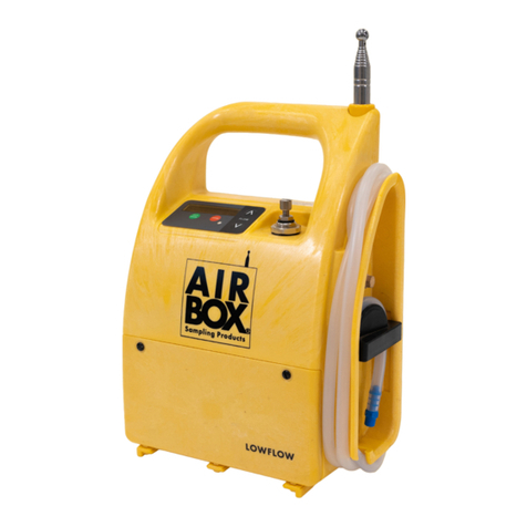
Airbox Sampling Products DATAFLOW User manual

User Manual
Specifications:- (tested with 0.8µm MCE filter)
Flow Range: Adjustable 5-10 l/min
Flow Stability: < 3% +/-
Battery Pack: 12.8V Lifepo4 12Ah Lithium
Charge Time: 6 hours
Duration: 12+ Hours @ 8l/min
Material: HF ABS
Waterproof: IP65
Dimensions: H38cm x W24cm x D12cm
Mast extends to: Up to 2.0 meters
Weight: 3kg
DATAFLOW
Issue 1
220628

Thank you for choosing this Airbox product. To ensure that you get the best possible
use from it, please read this manual carefully.
Airbox Sampling Products is part of the FermionX Group
12
Technical support
For all technical support or customer service enquiries
please contact us:
Warranty Registration
Don’t forget to register your new Airbox product by filling in the registration form
provided and returning it to us at the address below.
Alternatively you can do this online at: www.airboxsp.com
telephone: +44(0)1903 524 600
email: [email protected]
Airbox Sampling Products , Technology Centre,
Easting Close, Worthing, West Sussex BN14 8HQ
Table of contents
1. Installing the Airbox Dataow Software............................................................3
1.1 Compatible operating systems....................................................................................................3
1.2 Locating and loading the software.............................................................................................3
1.3 Airbox Dataow Application.........................................................................................................4
1.4 Airbox Dataow Application when connected to pump...................................................4
2. Preparing the Dataow pump for use................................................................5
2.1 Charging the battery......................................................................................................................5
2.2 Dataow setup .................................................................................................................................5
3. Presetting jobs on the Dataow.......................................................................6
3.1 Connecting the unit to the computer......................................................................6
3.2 Set up test data on Airbox Dataow Application............................................... 6
4. Selecting and entering jobs on the Dataow...................................................7
4.1 Selecting a previously saved job...................................................................................................8
4.2 Manually entering a job................................................................................................................8
4.2.1 Capacity test...................................................................................................................................8
4.2.2 Timed test........................................................................................................................................9
4.3 Logging period...............................................................................................................................9
4.4 Pin number.......................................................................................................................................9
4.5 Running Test....................................................................................................................................9
5. Checking live ow rates from a pump.............................................................10
6. Downloading data from the Dataow.............................................................11
6.1 Download test data......................................................................................................................11
7. Congure unit storage.........................................................................................11
8. Maintenance..........................................................................................................12
8.1 Replacing the battery...................................................................................................12
8.2 Replacing the mast.......................................................................................................12
8.3 Cleaning the unit...........................................................................................................12
9. Service and warranty.........................................................................................13
10. Troubleshooting...................................................................................................13
11. Parts........................................................................................................................14

3
1. INSTALLING THE AIRBOX DATAFLOW SOFTWARE
Load the USB stick provided with your DATAFLOW pump into your computer, open the
Airbox Dataflow Firmware folder
Firstly download both files (setup.exe & Dataflow Installer.msi)
Once downloaded, run the setup.exe file. You will be taken to the Welcome to the Dataflow
Setup Wizard window. Click Next.
The Select Installation Folder window opens. Click Browse and choose a destination on your
computer to store the software for easy access.
The Confirm Installation window opens. Click Next to start the installation.
The Installation Complete window opens. Click Close to exit.
The Airbox Dataflow application will appear in your file destination chosen and
automatically places a shortcut on your desktop
1.1 Compatible operating systems
The application is only compatible with Microsoft Windows operating systems
and will not work on the Mac OS X platform. The minimum recommended
requirement is Windows 7.
1.2 Locating and loading the software
Before you can preset and download data from your DATAFLOW pump you will need to
install the Airbox Dataflow Application.
4
1.3 Airbox Dataflow Application
1.4 Airbox Dataflow Application when connected to the pump
Download
CalibrationSetup
Troubleshooting Exit
To website
Pump not connected to computer
To website
Download Troubleshooting Exit

2. PREPARING THE DATAFLOW PUMP FOR USE
Before you use the DATAFLOW pump make sure it is fully charged.
2.1 Charging the battery
When the charger is plugged into the charging socket a red LED will be illuminated. The
LED will change to green when the battery is fully charged.
It takes approximately 6-8 hours to completely charge the battery.
CAUTION: Ensure you re-attach the blue charger cap to maintain the pump’s IP65
Waterproof and Dustproof rating.
2.2 DATAFLOW START UP
Make sure the application is open on the computer. Connect the USB cable to the
computer and to the pump.
Press start/pause to switch on the unit.
The display will show (in this order):
AIRBOX DATAFLOW
S/N:
Firmware revision:
Time and date
Last calibration date
Battery %
AIRBOX DATAFLOW
5 6
3.2 Set up Test Data on Airbox Dataflow Application
Press the Setup button on the application interface (see 1.4).
A new window opens.
Here you can set up all the data required to run a test.
First choose your language
The best way to use the DATAFLOW is to preset the jobs onto the pump before it is taken
out on site. Multiple jobs can be preset and saved in the application.
3. PRESETTING JOBS ON THE DATAFLOW
3.1 Connecting the unit to the computer
Open the Airbox Dataflow Application from the shortcut on your desktop. Connect
the USB cable to the computer and to the pump.
Start the pump as per 2.2 DATAFLOW START UP.

You now have a choice. When using the DATAFLOW, you can either:
Select the job you have previously set (see 4.1).
Or if no job has been previously set, you can manually Enter a job directly on to the
pump (see 4.2).
To choose an option, press start/pause and turn on the pump (see 2.2)
Press the start/pause to Select/Enter Job. Use the arrow keys to move between
Select and Enter.
If Select is chosen, see 4.1.
If Enter is chosen see 4.2.
4. SELECTING AND ENTERING JOBS ON THE DATAFLOW
Enter a Job Name
Enter a Location
Set up either a Capacity Test or Timed Test using the drop down menu in Mode
Enter the Flow (L/Min)
For Capacity Test, when entering the required Capacity (L) the Time (Mins) will
automatically be calculated.
For Timed Test when entering the required Time (Mins) the Capacity (L) will
automatically be calculated.
Choose a Sample Rate for data collection (see 4.3).
Set a PIN number if required (see 4.4).
Once all required fields are completed click on the Tick
The window will close and the job will now be stored on the Dataflow pump.
NOTE: You can set up multiple jobs.
When you have completed the set up, click on Disconnect From Unit and remove the
USB cable.
7 8
3.2 Set up Test Data on Airbox Dataflow Application (cont)
To select a job you have previously set up on the pump, (see section 3 on presetting
jobs) with Select showing on the display, press start/pause. Use the arrow keys to
scroll through and find the job you want to run.
Once you have located the correct job, press start/pause and Start Job - OK Yes is
displayed. Use the arrows to choose YES/NO/DELAY. Press start/pause to choose
option.
If DELAY is chosen, use the arrow keys to change the values and the start/pause to
scroll across the numbers. Once the values have been set, press start/pause and the
time will run down and start the test.
If NO is selected, you will be taken back to main screen.
4.1 Selecting a previously saved job
To manually enter a new job, with Enter showing on the display, press start/pause.
To Enter Job Number use the arrow keys to enter letters or numbers (up to a maximum
of 10 digits) The up arrow starts on the letter A, the down arrow on the number 9. Pressing
the start/pause moves the cursor on to the next digit.
When your happy with your job number press start/pause to set. If you enter it
incorrectly, press stop to clear the display and start again.
Once you have entered the job number you now have the choice of doing a Capacity
Test or a Timed Test. Use the arrow keys to choose.
4.2 Manually entering a job
4.2.1 Capacity Test
With Select Test Mode Capacity Test showing in the display, press start/pause.
The display will now show the default capacity of 480 litres.
Use the arrow keys to change the values and the start/pause to scroll across the
numbers. Once the values have been set, press start/pause until the display changes to
Enter Flow Rate and shows the default value of 08.0 litres/min.
Use the arrow keys to change the values and the start/pause to scroll across the
numbers. Once the values have been set, press start/pause until the display changes to
‘Logging Period’ and shows the default value of 1 second(s). Continue from 4.3.

9
4.2.2 Timed Test
With Select Test Mode Timed Test showing in the display, press start/pause.
The display will now show the default flow rate of 08.0 litres/min.
Use the arrow keys to change the values and the start/pause to scroll across the
numbers. Once the values have been set, press start/pause until the display changes to
Enter Run Time and shows the default value 01:00:00.
4.4 Pin Number
Pin Number allows you to enter a four digit security number to pin protect an individual
pump so that it can only be accessed by the person who sets the pin. Use the arrow keys to
select yes or no.
If Yes is selected, Enter PIN Number is displayed. Use the arrow keys to enter values and
start/pause to scroll across them. Press start/pause to continue and job is saved to
memory and Start Job - OK Yes is displayed.
10
4.3 Logging Period (Sample rate)
The Logging Period (Sample rate) has data capture of flow rate, time stamp, and
accumulated capacity. You have a choice to log this data every 1 second, 30 seconds or
60 seconds.
Use the arrow keys to choose the required logging period/sample time, then press
start/pause until the display shows Set PIN Number.
If YES is chosen, test will begin.
You can pause the test by pressing start/pause.
You can stop the test by pressing stop. You will be asked if you are sure. If yes press stop.
When the job is completed, the pump will stop. Test Completed and the accumulated
capacity will be displayed.
Press stop to return to the start menu. Press stop again to shut the unit down.
Data is saved and ready for download.
4.5 Running Test
Use the arrow keys to change the values and the start/pause to scroll across the
numbers. Once the values have been set, press start/pause until the display changes to
Logging Period and shows the default value of 1 second(s).
Use the arrows to choose YES/NO/DELAY. Press start/pause to choose option.
If DELAY is chosen, use the arrow keys to change the values and the start/pause to
scroll across the numbers. Once the values have been set, press start/pause and the
time will run down and start the test.
If NO is selected, job is saved to memory and you will be taken back to main screen.
4.5 Running Test (cont)
5. CHECKING LIVE FLOW RATES ON A PUMP
While pump is running you can check live flow rates.
Open the application, and press the Download Icon (See 1.4) on the application
interface. A new window will open showing a list of the saved jobs on the pump (see 6.1
Download Test Data).
On the bottom right corner you will see a Pulse Icon, click on this. A new window will
open showing a list of pumps that are running and are either connected via USB cable to
the PC, or via bluetooth.
Choose which pump to view via the S/N illustrated, and wait until the 0 in the x axis
meets the y axis, it will then start to record the live flowrates onto a graph for the user to
ensure the pump is still running at the correct flow rate.

6. DOWNLOADING DATA FROM THE DATAFLOW
Make sure the application is open on the computer. Connect the USB cable to the
computer and to the pump.
Press start/pause to switch on the unit. (See 2.2)
6.1 Download Test Data
Press the Download icon (see 1.4) on the application interface. A new window opens
showing a list of the saved jobs on the pump.
11
7. CONFIGURE UNIT STORAGE
The DATAFLOW can store a large number of jobs in it’s memory. The application interface
will show how much memory has been used and is left.
You can easily manage this memory by clicking on the Setup button (see 1.4). This
brings up a new window where you can erase the complete device data.
Caution: Make sure you have downloaded and saved the test data for each job before
you erase the complete memory.
The DATAFLOW pump has been specifically designed to make replacing the battery a
quick and easy task. Simply half turn the two screws on the front of the battery housing,
unclip the connector, remove the battery and replace.
NOTE: This is made easier if you lay the pump on its back.
8.2 Replacing the mast
The mast is secured on the unit in a threaded housing, so to replace just unscrew and
remove. We would also recommend removing the mast when cleaning the unit (8.3).
8.3 Cleaning the unit
The casing of the DATAFLOW pump is made from a hard wearing ABS structural foam,
making it incredibly rugged and also very easy to clean. Tested to IP65 standards
(‘Protected against low pressure water jets from any direction.’) the unit can be cleaned
under a shower hose.
NOTE: Do NOT Submerge the product fully in water.
8. MAINTENANCE
8.1 Replacing the battery
12
Click on the correct job number and choose a file format (XLS, PDF or CSV) to download.

13 14
The DATAFLOW pump is covered by our exclusive warranty and in the event that the
unit fails we will undertake the repair free of charge for up to 2 years from the date of
purchase. The warranty covers the costs of materials and labour (excluding the battery
and mast and with the shipping costs to be covered by the customer) and is valid under
the following conditions:-
a) The warranty registration card must be received by us within four weeks of the
date of purchase. This can be done online in the service section of the website.
b) The defect must not have been caused by improper handling or misuse.
c) Return the unit to us only in its original packing and in the decontamination bag
provided by Airbox. We will not assume responsibility for transport damage under
any circumstances.
d) Warranty sticker must remain intact, showing the user has not attempted to gain access
inside the unit
e) A short description of the defect must be included with the returned unit.
9. SERVICE AND WARRANTY
10. TROUBLESHOOTING
Pump will not start, red LED illuminated.
Battery voltage maybe too low, check the battery level and recharge the battery.
If the pump still doesn’t start, contact the Airbox team.
Pump will not start, no display
Flat battery, recharge or replace the battery.
If the pump still doesn’t start, contact the Airbox team.
Flow rate doesn’t reach required level
Firstly check for kinks and that the sampling head is not blocked, then re-calibrate against
external flow meter
Battery voltage maybe too low, check the battery level and recharge the battery.
If flow rate is still insufficient, contact the Airbox team.
Pump stops while running, red LED illuminated
Check tube for kinks and that the sampling head is not blocked.
Flat battery, recharge or replace the battery.
11. PARTS
Product Code Name Description
P02133 DATAFLOW DATAFLOW Air Sampling Pump (with UK/
EU charger)
P02133/KIT DATAFLOW kit DATAFLOW Air Sampling Pump (with UK/
EU charger, sampling head & spare mast)
P01839 Sampling head Air sampling head
P035620LF Dataflow Charger Battery charger DATAFLOW 14.6V 3A
Lithium
P T 3 5 619 DATAFLOW Battery 12.8V Lifepo4 12Ah Lithium
PT29482LF DATAFLOW mast Telescopic mast for
DATAFLOW/VARIFLOW -2m
PT28297LFKIT Cap & Plug Kit Sampling head cap & plug kit - (pack of
10)
PT28299LF White filter support
pad
Filter support pad 25mm porous plastic
(pack of 10)
PT28551LF Metal filter support
grid
Filter support grid 25mm mesh metal
PT28301LF Thin sampling head
O-ring
25mm/OD 1.9mm/CS Virgin PTFE
(pack of10)
PT27550LF Thick sampling head
O-ring 25mm/OD 2.75mm/CS Virgin PTFE
Table of contents
Other Airbox Sampling Products Water Pump manuals
Popular Water Pump manuals by other brands

Teral
Teral LHW-e instruction manual

Parker
Parker A4W Series Product bulletin

Franklin Fueling Systems
Franklin Fueling Systems FE PETRO PMA 75 Replacement instructions

BOC Edwards
BOC Edwards EO2K instruction manual

Resol
Resol FlowSol D Installation, Operation, Commissioning, Maintenance

Conair
Conair RG Series user guide