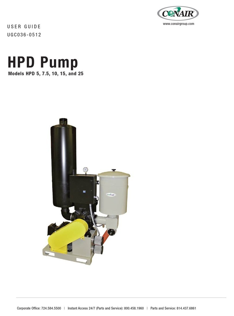
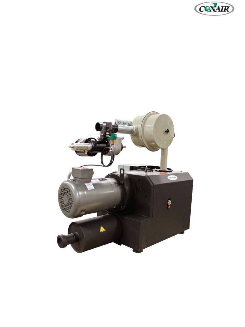
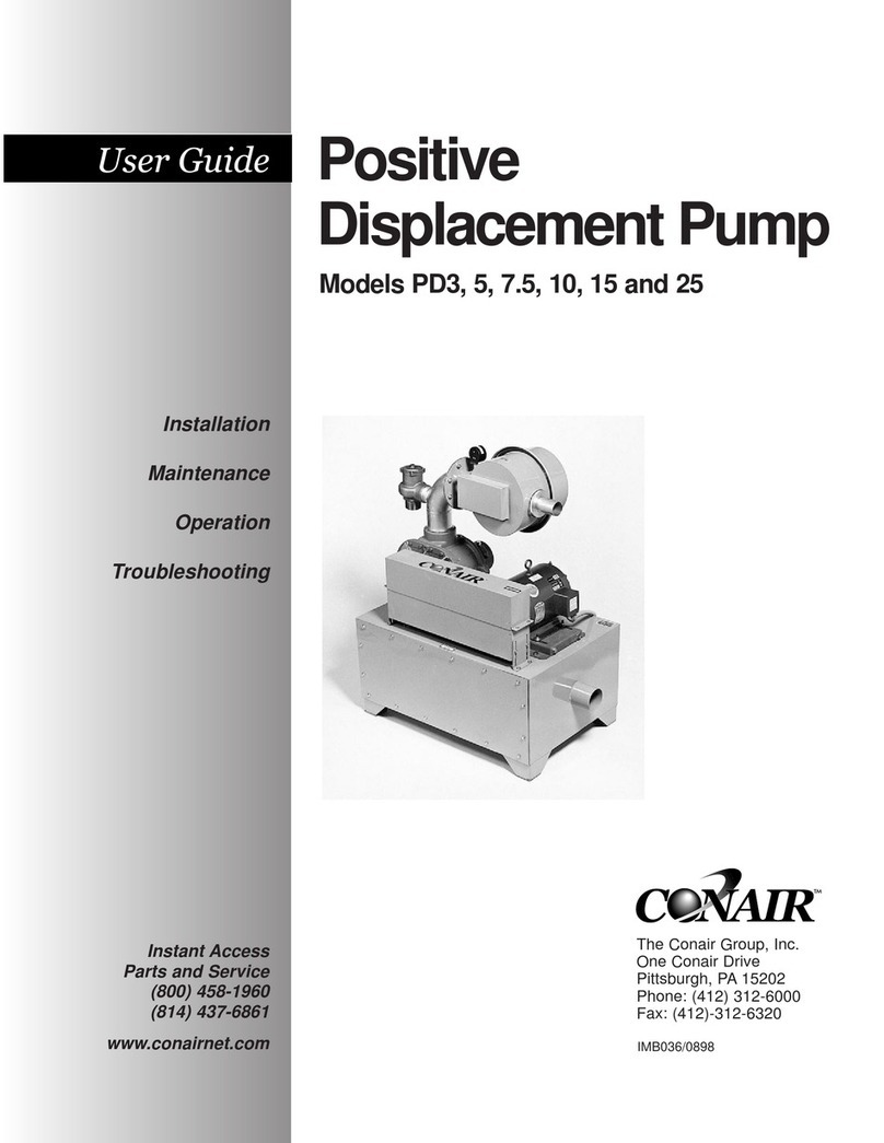
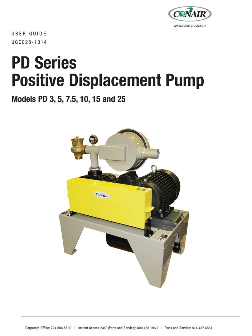
Conair RG Series User manual

RG Series Pumps
Corporate Office: 412.312.6000 lInstant Access 24/7 (Parts and Service): 800.458.1960 l Parts and Service: 814.437.6861
USER GUIDE
UGC025/0905
www.conairnet.com
INTRODUCTION • Purpose of the User Guide • How the guide is organized • Your responsibilities as a user • ATTENTION:
Read this so no one gets hurt • DESCRIPTION • What is the RG Pump • Typical applications • How it works •
Specifications: RG Pump • INSTALLATION • Unpacking the boxes • Preparing for installation • Installation -
Mechanical • Installation - Electrical • Installation with Idle Mode Valve-Mechanical • Installation with Idle Mode Valve-
Electrical and the Transformer • OPERATION • RG Pump Operation • Sequence of Operation without Idle Mode •
Sequence of Operation without Idle Mode Valve

Please record your equipment’s
model and serial number(s) and
the date you received it in the
spaces provided.
It’s a good idea to record the model and serial number(s) of your equipment and
the date you received it in the User Guide. Our service department uses this infor-
mation, along with the manual number, to provide help for the specific equipment
you installed.
Please keep this User Guide and all manuals, engineering prints and parts lists
together for documentation of your equipment.
Date:
Manual Number: UGC025/0905
Serial Number(s):
Model Number(s):
DISCLAIMER: The Conair Group, Inc., shall not be liable for errors contained in this User Guide or
for incidental, consequential damages in connection with the furnishing, performance or use of
this information. Conair makes no warranty of any kind with regard to this information, including,
but not limited to the implied warranties of merchantability and fitness for a particular purpose.
Copyright 2005 l The Conair Group l All rights reserved

Table of Contents
1-1 Introduction
Purpose of the user guide . . . . . . . . . . . . . . . . . . . . . . . . . . . . . . . . 1-2
How the guide is organized . . . . . . . . . . . . . . . . . . . . . . . . . . . . . . 1-2
Using the RG Pumps . . . . . . . . . . . . . . . . . . . . . . . . . . . . . . . . . . . . 1-3
Your responsibilities as a user. . . . . . . . . . . . . . . . . . . . . . . . . . . . . 1-3
ATTENTION: Read this so no one gets hurt . . . . . . . . . . . . . . . . . . . 1-4
2-1 Description
What is the RG Pump? . . . . . . . . . . . . . . . . . . . . . . . . . . . . . . . . . . .2-2
Typical applications . . . . . . . . . . . . . . . . . . . . . . . . . . . . . . . . . . . . .2-2
How it works . . . . . . . . . . . . . . . . . . . . . . . . . . . . . . . . . . . . . . . . . .2-3
Specifications: RG Pump . . . . . . . . . . . . . . . . . . . . . . . . . . . . . . . . . 2-5
3-1 Installation
Unpacking the boxes . . . . . . . . . . . . . . . . . . . . . . . . . . . . . . . . . . . 3-2
Preparing for installation . . . . . . . . . . . . . . . . . . . . . . . . . . . . . . . . . 3-2
Installation - Mechanical . . . . . . . . . . . . . . . . . . . . . . . . . . . . . . . . . 3-3
Installation - Electrical. . . . . . . . . . . . . . . . . . . . . . . . . . . . . . . . . . . 3-4
Installing Ratio, Line or Inlet Flapper Valves. . . . . . . . . . . . . . . . . . . 3-8
Installation with Idle Mode Valve - Mechanical . . . . . . . . . . . . . . . . 3-5
Installation with Idle Mode Valve
-Electrical and the Transformer . . . . . . . . . . . . . . . . . . . . . . . . 3-11
Table of Contents l i

4-1 Operation
Checking Rotation . . . . . . . . . . . . . . . . . . . . . . . . . . . . . . . . . . . . . . 4-2
Sequence of Operation without Idle Mode . . . . . . . . . . . . . . . . . . . . 4-2
Sequence of Operation without Idle Mode Valve and Control . . . . . . 4-4
5-1 Maintenance
Maintenance . . . . . . . . . . . . . . . . . . . . . . . . . . . . . . . . . . . . . . . . . . 5-2
6-1 Troubleshooting
Before Beginning. . . . . . . . . . . . . . . . . . . . . . . . . . . . . . . . . . . . . . . 6-2
A few words of caution . . . . . . . . . . . . . . . . . . . . . . . . . . . . . . . . . 6-2
Conveying Problems . . . . . . . . . . . . . . . . . . . . . . . . . . . . . . . . . . . . 6-3
AAppendix
We’re here to help . . . . . . . . . . . . . . . . . . . . . . . . . . . . . . . . . . . . . A-2
How to contact customer service . . . . . . . . . . . . . . . . . . . . . . . . . . A-2
Before you call... . . . . . . . . . . . . . . . . . . . . . . . . . . . . . . . . . . . . . . A-2
Equipment guarantee . . . . . . . . . . . . . . . . . . . . . . . . . . . . . . . . . . A-3
Performance warranty . . . . . . . . . . . . . . . . . . . . . . . . . . . . . . . . . . A-3
ii l Table of Contents

Introduction
Purpose of the user guide. . . . . . . . . . . . . . 1-2
How the guide is organized. . . . . . . . . . . . . 1-2
Using the RG Pumps . . . . . . . . . . . . . . . . . 1-3
Your responsibilities as a user. . . . . . . . . . . 1-3
ATTENTION:
Read this so no one gets hurt . . . . . . . . 1-4
SECTION
1
Introduction l 1-1
1
Introduction

✐
Purpose of the User Guide
This User Guide describes the Conair RG Pump and explains step-by-
step how to install, operate, maintain and repair this equipment.
Before installing this product, please take a few moments to read the User
Guide and review the diagrams and safety information in the instruction
packet. You also should review manuals covering associated equipment in
your system. This review won’t take long, and it could save you valuable
installation and operating time later.
How the Guide is Organized
Symbols have been used to help organize the User Guide and call your
attention to important information regarding safe installation and operation.
Symbols within triangles warn of conditions that could be hazardous to users or
could damage equipment. Read and take precautions before proceeding.
Numbers indicate tasks or steps to be performed by the user.
A diamond indicates the equipment’s response to an action performed by the user.
An open box marks items in a checklist.
A circle marks items in a list.
Indicates a tip. A tip is used to provide you with a suggestion that will help you with
the maintenance and the operation of this equipment.
Indicates a note. A note is used to provide additional information about the steps
you are following throughout the manual.
1
◆
❒
•
✒
1-2 l Introduction

Introduction l 1-3
Using the RG Pumps
Each RG Pump is designed to work within a central vacuum system consisting
of:
• Vacuum Receiver
• Dust Collector
• Central Loading Control(s)
Separate instructions are provided for these devices and should be referred to as
needed to fully understand the operation of the entire system.
Your Responsibility as a User
You must be familiar with all safety procedures concerning installation, opera-
tion and maintenance of this equipment. Responsible safety procedures include:
•Thorough review of this User Guide, paying particular attention
to hazard warnings, appendices and related diagrams.
•Thorough review of the equipment itself, with careful attention
to voltage sources, intended use and warning labels.
•Thorough review of instruction manuals for associated equipment.
•Step-by-step adherence to instructions outlined in this User Guide.
1
Introduction

ATTENTION:
Read this so no one gets hurt
We design equipment with the user’s safety in mind. You can avoid the potential
hazards identified on this machine by following the procedures outlined below and
elsewhere in the User Guide.
WARNING: Improper installation, operation, or
servicing may result in equipment damage or
personal injury.
This equipment should be installed, adjusted, and serviced by qualified
technical personnel who are familiar with the construction, operation,
and potential hazards of this type of machine.
All wiring, disconnects, and fuses should be installed by qualified elec-
trical technicians in accordance with electrical codes in your region.
Always maintain a safe ground. Do not operate the equipment at power
levels other than what is specified on the machine serial tag and data
plate.
WARNING: Voltage hazard
This equipment is powered by a control voltage, as specified on the
machine serial tag and data plate. See separate loading control manu-
al.
A properly sized conductive ground wire from the incoming control
wiring must be connected to the ground terminal inside the electrical
enclosure. Improper grounding can result in severe personal injury and
erratic machine operation.
Always disconnect and lock out the incoming main power and control
sources before opening the electrical enclosure or performing non-
standard operating procedures, such as routine maintenance. Only
qualified personnel should perform troubleshooting procedures that
require access to the electrical enclosure while power is on.
1-4 l Introduction

Description
What is the RG Pumps? . . . . . . . . . . . . . . . 2-2
Typical applications. . . . . . . . . . . . . . . . . . 2-2
How it Works . . . . . . . . . . . . . . . . . . . . . . 2-3
Specifications: RG Pumps . . . . . . . . . . . . . . 2-5
SECTION
2
2
Description

What is the RG Pumps?
RG series vacuum pumps are vacuum pump and motor units designed to provide
vacuum power for the conveyance of plastic pellets and regrinds through connec-
tion with vacuum receivers and a dust collector. Control of the pump is provided
by a loading control system, interconnected with the receivers. The pump provides
vacuum energy as indicated on its vacuum gauge, to the vacuum receiver(s) to
allow material transfer. The pump motor operates on 3 phase electrical power con-
trolled by a magnetic starter mounted to the pump assembly. The loading control
provides a start signal to the pump in response to the need for material by the vac-
uum receiver(s).
In addition to various pump and motor sizes, pumps are provided in either single
or dual stage models, indicating the number of suction stages provided to create a
vacuum. Dual stage pumps create stronger levels of vacuum.
Typical Accessories and Options
Vacuum pumps traditionally work directly with Dust Collectors or other filters that
are designed to remove plastic dust from the incoming air line to prevent contami-
nant's from circulating through the vacuum pump. In some cases, operation of the
pump without a dust collection system can create pump damage or a hazardous
condition resulting from flammable or at least low melt point plastic material being
exposed to the elevated operating temperature of the pump.
A common option is an Idle Mode Valve that allows the vacuum pump to remain
operating for a period of time after the run signal from the loading control is inter-
rupted. This option can greatly lengthen pump life by eliminating rapid start/stop
cycles common to many vacuum loading systems. Instead of shutting down, the
pump continues to run for a minimum of five minutes while vacuum pressure is
relieved through a compressed air operated valve that bleeds ambient air into the
vacuum inlet line of the pump. This optional valve is usually shipped loose with
the pump and may be installed anywhere in the vacuum line between the pump
and the dust collector with the supplied compression couplings. The valve gets its
operating signal from a combination Transformer/Idle Mode Control box, mounted
next to and interconnected with the pump starter and clean compressed air must be
provided to the valve solenoid for it to operate.
2-2 l Description

Specifications
Description l 2-3
2
Description
Figure A
C
B
A
MODEL RG1-3 RG1-6 RG1-11 RG2-5 RG2-8 RG2-16
Single Stage or Dual Stage Single Single Single Dual Dual Dual
Performance Characteristics
60 Hz 50Hz 60 Hz 50 Hz 60 Hz 50 Hz 60 Hz 50 Hz 60 Hz 50 Hz 60 Hz 50 Hz
Motor Hp* 3.4 N/A 6.2 5.4 11.5 10.1 5.1 4.4 8.45 7.4 16.9 14.8
Equivalent kW {2.6} N/A {4.6} {4.0} {8.6} {7.5} {3.8} 3.3 {6.3} {5.5} {12.6} {11.0}
Line size inches 1.5 N/A 2.0 1.5 2.5 2.0 1.5 1.5 2.0 1.5 2.5 2.0
Airflow at material pickup ft3/min 55 N/A 76 43 135 76 41 60 74 41 138 74
Airflow at pump inlet ft3/min 70 N/A 101 57 191 107 67 79 122 69 226 131
Pump pressure inches Hg Vac.
†
-6.2 N/A -7.4 -7.4 -8.8 -8.4 -11.7 -7.3 -11.7 -12.2 -11.7 -12.9
Sound level (dba) 70 N/A 72 69 74 70 71 67 76 73 78 74
Inlet orientation (see Fig. A) Back Back Back Front Back Back
Outlet orientation (see Fig. A) Back Back Back Back Side Back
Dimensions inches {mm}
A - Height 14 {355.6} 16 {406.4} 21 {533.4} 25 {635.0} 17 {431.8} 23 {584.2}
B - Width 22 {558.8} 24 {609.6} 31 {787.4} 36 {914.4} 27 {685.8} 32 {812.8}
C - Depth 15 {381.0} 18 {457.2} 21 {533.4} 18 {457.2} 28 {711.2} 28 {711.2}
Weight lb {kg}
Shipping 60 {27.2} 103 {46.7} 302 {136.9} 116 {52.6} 164 {74.4} 472 {214.1}
Installed 55 {24.9} 93 {42.2} 282 {127.9} 106 {48.1} 154 {69.8} 452 {205.0}
Voltage Full load amps (FLA)
230V (220-275)/3 phase/60 Hz 10.3 N/A 16.4 N/A 30 N/A 14.2 N/A 23 N/A 50.2 N/A
460V (380-480)/3 phase/60 Hz 6 N/A 9.5 N/A 17.3 N/A 8.2 N/A 13.3 N/A 29 N/A
400V (345-415)/3 phase/50 Hz N/A N/A N/A 9.5 N/A 16.7 N/A 7.5 N/A 13.3 N/A 28
575V/3 phase/60 Hz 4.5 N/A 7.6 N/A 13.6 N/A 5.4 N/A 10.4 N/A 20.4 N/A
Motor Type TEFC
SPECIFICATION NOTE:
* Hp rating is based on the kW rating of the blower. Not comparable to positive Hp ratings.
†
Hg Vac. : Mercury Vacuum
N/A: Not Available.
Specifications can change without notice. Contact your Conair representative for the most current information.


Installation l 3-1
Installation
Unpacking the boxes . . . . . . . . . . . . . . . . . 3-2
Preparing for installation . . . . . . . . . . . . . . 3-2
Installation - Mechanical . . . . . . . . . . . . . . 3-3
Installation - Electrical . . . . . . . . . . . . . . . 3-4
Installation with Idle Mode Valve
- Mechanical. . . . . . . . . . . . . . . . . . . . 3-5
Installation with Idle Mode Valve
- Electrical and the Transformer. . . . . . . 3-6
SECTION
3
3
Installation

3-2 l Installation
Unpacking the Boxes
RG pumps are typically shipped bolted to a pallet and either enclosed by a box or
simply wrapped in protective plastic sheeting.
1Carefully remove the box or wrap and unbolt the unit from the shipping
skid. When unpacking, be sure to locate any accessories or other loose parts
that may have been consolidated in the shipment along with the instruction
packet. Make sure that all packing material is completely removed from the
pump, paying special attention to the inlet and outlet tubes and crevice areas, to
prevent potential damage caused by the packing materials during the heat and
suction of operation.
2Once the pump is unbolted from the pallet, a lifting hook, centrally located
on the top of the pump assembly may be used to lift the pump with a crane
or other lifting device. Use caution as the pump is transferred off the skid and
into the desired location for installation.
Preparing for Installation
The pump should be located in a protected, indoor location, typically near the dust
collector or pump protection filter. 3 phase power will be required and a fused
disconnect switch (not included) is typically used near the pump. If the Idle Mode
Valve option is being utilized, then compressed air will also be required near the
pump. Tubing connections to the pump are typically made with a flex hose to
allow easy connections to be made between the dust collector and pump.
Securing the pump to the floor with bolts is not strictly required, but is recom-
mended to prevent the minimal motion that could occur as the pump ages or in the
event of malfunction caused by contamination of the air stream.
The pump will not require regular maintenance, but should still be located where it
is accessible and where its vacuum gauge is easily read by set-up and operation
personnel. In addition, the pump’s magnetic starter (and optional Idle Mode
Control) is mounted to the unit and may need to be accessed for service on occa-
sions.
WARNING: You are
responsible for the
structural integrity of
this installation.

Installation l 3-3
Installation - Mechanical
1Use the lifting hook on the top of the pump to gently lower it into its oper-
ating location.
2Use care in orienting the pump for easy access to its pump starter and
clearance for the opening of its lid and allowing easy visibility of its vacuum
gauge.
3Note the inlet and outlet stubs of the pump: Generally, the outlet will simply
exhaust conveying air out of the blower, but it may need to be plumbed to a dry
air conveying line in some applications. It may also be plumbed outside if
desired, as long as the exhaust line expands the size of the tube as it follows its
path to exhaust. The inlet stub will be connected to the dust collector or filter
of the system and may also contain the optional Idle Mode Valve (see section 3,
Installation of the Idle Mode Valve.)
4The use of flex hose for pump connections is recommended, to allow easy
movement or service if ever needed. Line up and coordinate all connections to
allow for easy connections, but wait until pump rotation has been established
(and corrected, if need be) before completing installation.
5If tubing is to be used, employ OD matched compression couplings, with
tubing fully seated and butted against adjacent tubing in the center of the cou-
pling.
6Tighten all coupling bolts evenly. Tubing must not put a strain on the inlet or
outlet of the pump connections or eventual leaks will occur.
7Maintain an air space all around the pump for ventilation. Do not block or
cover any portion of the cooling fins that would prevent free air movement or
reduce cooling effectiveness.
3
Installation

Installation - Electrical
1A 3 phase, fused disconnect switch is typically provided near the pump loca-
tion and matched to the voltage and full load amps of the pump, listed on its
serial tag.
2An appropriately sized cable or rigid or flexible conduit must be provided
from the disconnect to the pump starter, located on the side of the pump
assembly. Follow all local and industrial electrical codes for your location and
connect the incoming power from the disconnect into the starter via the center
hole of the starter box.
3If a Transformer/Idle Mode control is included, refer to section 3,
Installation with Idle Mode Valve-Electrical and the Transformer. Otherwise,
the 120 Volts AC pump start signal from the loading control (see separate
instructions) is connected into the pump starter via the left hand knockout cable
entry point on top of the starter. Connect the start signal to the coil circuit of
the starter according to code and the instructions on the lid of the starter.
4Assure that all connections are proper, firm and routed away from moving
or hot parts and close the lid of the starter. Electrical connections are now
complete.
3-4 l Installation
All wiring, disconnects
and fuses should be
installed by qualified
electrical technicians
in accordance with
electrical codes in your
region. Always main-
tain a safe ground.

Installation l 3-5
Installation with Idle Mode Valve-
Mechanical
1The Idle Mode Valve provides ambient air relief to the pump for 5 minutes
after running, to eliminate rapid stop and start cycles from damaging the
pump. The valve is provided with a "T" junction tube at the top that matches
the line size of the pump and is intended to be installed in the vacuum line
between the pump and the loading system's dust collector or filter.
2Locate the valve near the vacuum line inlet of the pump and position one
open end of the "T" towards the pump and the other end towards the dust
collecting filter. Orientation of the valve and the "T" may be in any direction
to suit the installation, but note that compressed air must be plumbed to the
solenoid, so allow room for this connection. Also note that ambient air will be
sucked into the vent plate of the valve in operation so it should be oriented
away from heat, dust filled areas (floors, etc) or hot exhausts from other
machines, including the pump itself.
3Use the supplied compression couplings or connect directly to the "T" with
flex hose, to install the valve between the pump and dust collector. The
valve should be secured against motion using its "T", its body or the vent plate
bolts, but without blocking free air movement into the valve's vent.
4Clean, dry compressed air must be plumbed into the solenoid of the valve
via its open, ¼" NPT fitting. Air should be in the range of 60 to 90 psi, approx-
imately 1 CFM. A shut-off valve for the compressed air line is recommended,
to allow future service of the Idle Mode valve.
3
Installation

Installation with Idle Mode Valve-
Electrical and the Transformer
The Transformer/Idle Mode Control is mounted next to and interconnected with
the pump's starter and provides both a transformer for 120 volts from the 3 phase
pump supply as well as a control for the Idle Mode Valve.
1The signal from the loading control to the pump must be connected to the
Transformer/Idle Mode Control and the Idle Mode Valve itself connects to
the Transformer/Idle Mode Control.
2Disconnect the 3 phase power before making any connections to the
Transformer/Idle Mode Control, the Transformer/Idle Mode Control is ener-
gized when the pump starter box is energized.
3The vacuum pump start signal from the loading control must be wired into
the Transformer/Idle Mode Control via the cord grip on the side of the
control. Inside, a terminal strip is provided for connecting the signal. In opera-
tion, this signal triggers the Idle Mode control function and the Idle Mode con-
trol, and in turn, energizes the vacuum pump starter. Connections for the start
signal from the loading control are indicated on the label on the outside of the
Transformer/Idle Mode Control box and should be followed carefully. The
incoming signal may be 24 VDT or 120 VAC and the control will automatically
adjust to the input voltage. Be sure to properly terminate the ground wire.
4Wire the Idle Mode Valve into the Transformer/Idle Mode Control. The
120 volt AC Idle Mode Valve is equipped with a cable set that may be cut to
length once the location of the valve is determined and the cable is carefully
routed back to the Transformer/Idle Mode Control. In addition, the Valve
assembly is equipped with a cable grip for installation in the Transformer/Idle
Mode Control.
5Remove a knock-out or hole plug in the lower cover panel of the Transformer
/Idle Mode Control and install the cable grip and Idle Mode Valve cable.
6Connect to the internal term strip according to the instructions on the out-
side of the Transformer /Idle Mode Control. Be sure to properly terminate
the ground wire.
3-6 l Installation

3
Installation

This manual suits for next models
6
Table of contents
Other Conair Water Pump manuals
Popular Water Pump manuals by other brands

Star
Star ES05S manual

Wallenstein
Wallenstein PTO62 installation instructions

Grundfos
Grundfos SL1 Series instructions

TECALEMIT
TECALEMIT Visconet II operating manual

ITT
ITT Goulds Pumps XHD Series Installation, operation and maintenance manual

Agilent Technologies
Agilent Technologies TriScroll 600 Series MAJOR MAINTENANCE MANUAL

Barnes
Barnes PGPP Series installation manual

QEP
QEP STK 60095 owner's manual

Giant
Giant LP250 Operating instructions/ repair and service manual

Flotec
Flotec FPSC3350A owner's manual

Nordson EFD
Nordson EFD MicroCoat MC600 operating manual

Pump House
Pump House PH-20-STA Installation, operating and maintenance instructions