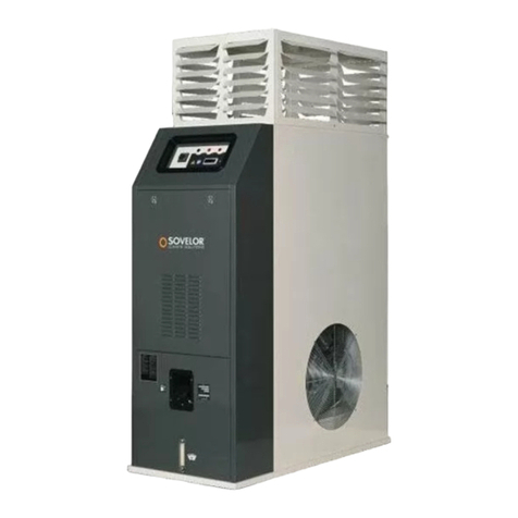
Airchaud Diffusion FARM 95 User manual

Fiche technique
SO FARM115 (vertical)
L-L 230.04-BM 3 / 68
SCHÉMA DE FONCTIONNEMENT - CONTROL BOARD
1
SORTIE AIR CHAUD
HOT AIR OUTFLOW
2
CHEMINEE
CHIMNEY
3
VENTILATEUR REFROIDISSEMENT
COOLING FAN
4
CHAMBRE DECOMBUSTION
COMBUSTION CHAMBER
5
BRULEUR
BURNER
6
BOITIER THERMOSTATS F+ L1 + L2
THERMOSTATS F+ L1+ L2BOX
5 4 3
5
2
1
6
SIRET : 444 448 898 00015 Fax : 03 88 08 67 39 www.airchaud-diffusion.fr 2
SOVELOR-DANTHERM / AIRCHAUD DIFFUSION | SO FARM115 (VERTICAL) | 11/2022

Fiche technique
SO FARM115 (vertical)
L-L 230.04-BM 4 / 68
TABLEAU DE COMMANDE - CONTROL PANEL
a INTERRUPTEUR CHAUFFAGE-VENTILATION
HEATING-VENTILATION SWITCH
b TEMOIN TENSION
VOLTAGE LAMP
c TEMOIN THERMOSTATS DE SURCHAUFFE, L1, L2
OVERHEAT THERMOSTATS CONTROL LAMP, L1, L2
d PRISE THERMOSTAT D’AMBIANCE
ROOM THERMOSTAT PLUG
e PRISE POUR BOITIER THERMOSTATS F + L1 + L2
SOCKET FOR THERMOSTATS F + L1+ L2 BOX
f PRESSE-CÂBLES POUR CÂBLE D'ALIMENTATION
CABLE CLAMP FOR POWER CABLE
g THERMOSTAT VENTILATEUR, F
FAN THERMOSTAT, F
8 THERMOSTAT DE SECURITÉ DE SURCHAUFFE, L1
OVERHEAT SAFETY THERMOSTAT, L1
i THERMOSTAT DESECURITE AREARMEMENT MANUEL, L2
LIMIT THERMOSTAT WITH MANUAL RESTART, L2
l TÉMOIN BLOCAGE VENTILATEUR (uniquement pour modèles triphasés)
FAN BLOCK LAMP (for 3-phase models only)
a b
d
c l
f
e
g
h
i
SIRET : 444 448 898 00015 Fax : 03 88 08 67 39 www.airchaud-diffusion.fr 3
SOVELOR-DANTHERM / AIRCHAUD DIFFUSION | SO FARM115 (VERTICAL) | 11/2022

Fiche technique
SO FARM115 (vertical)
FR
L-L 230.04-BM 12 / 68
IMPORTANT
Avant toute utilisation du générateur, nous vous prions de lire attentivement toutes les instructions pour l'emploi mentionnées
ciaprès et d'en suivre scrupuleusement les indications. Le constructeur n'est pas responsable des dommages aux personnes
et/ou aux biens dus à une utilisation impropre de l'appareil.
Ce livret d'utilisation et d'entretien est partie intégrante de l'appareil. Il doit donc être conservé soigneusement et accompagner
l'appareil en cas de revente.
1. DESCRIPTION
Les générateurs d’air chaud ci-décrits sont destinés au chauffage de
locaux de moyennes-grandes dimensions, qui requièrent un
système de chauffage fixe. En particulier, ils sont conçus pour le
chauffage de locaux destinés à accueillir des serres et/ou des
élevages d’animaux.
L'air comburant, c'est-à-dire l'air nécessaire à la combustion, est
directement aspiré par le brûleur (6) fixé sur la machine. Cet air peut
être prélevé :
• de l’extérieur, en utilisant une gaine flexible de raccordement
(disponible en tant qu’accessoire), ce qui permet d’éviter de
consommer l’oxygène du local à chauffer, ou bien
• à l’intérieur du local à chauffer ; dans ce dernier cas, le local doit
être correctement ventilé afin d’assurer un recyclage suffisant de
l’air.
Le flux d’air chaud est, quant à lui, mis en mouvement par un moto-
ventilateur hautes performances (4) : l'air est réchauffé par l'énergie
thermique développée pendant la combustion et transmise par des
fumées chaudes à l'air frais, à travers les surfaces métalliques
étanches de la chambre de combustion et de l'échangeur thermique.
Après avoir été refroidis, les produits de la combustion sont
acheminés vers une gaine d'évacuation et éliminés à travers une
cheminée ou un collecteur de fumées dont les dimensions doivent
en garantir l'évacuation.
Les générateurs d'air chaud peuvent fonctionner avec des brûleurs
ayant des modes de fonctionnement ON-OFF et alimentés au fuel.
Attention
Seuls les brûleurs approuvés par le constructeur et
indiqués dans le TABLEAU DES CARACTÉRISTIQUES
TECHNIQUES peuvent être utilisés.
Le remplacement du brûleur par un brûleur non d'origine,
même s'il présente les mêmes caractéristiques que le
brûleur d'origine, entraînera la déchéance de la
certification et de la garantie.
Tous les générateurs d’air chaud sont dotés d’un équipement
électronique de contrôle de la flamme ainsi que d’autres dispositifs :
• dispositifs de sécurité (thermostat de sécurité à réarmement
manuel, contrôle de flamme, pressostat d’air), qui interviennent en
cas de graves dysfonctionnements, endéclenchant un « blocage »
de sécurité : dans ce cas, le générateur s’arrête, le bouton (d)
s’allume en rouge fixe (signalisation de blocage) et le
fonctionnement ne pourra reprendre qu’après avoir localisé et
éliminé le problème à l’origine du blocage ;
• dispositifs de commande (thermostat ventilateur, thermostat
brûleur, contrôle de tension, pressostat gaz), qui interviennent en
cas d’anomalies non graves de fonctionnement ou d’alimentation,
en provoquant l’arrêt temporaire du générateur d’air chaud ; dans
ce cas, le générateur redémarrera automatiquement dès le
rétablissement des conditions normales de fonctionnement.
Le paragraphe “ANOMALIES DE FONCTIONNEMENT, CAUSES ET
SOLUTIONS” décrit toutes les possibles anomalies de
fonctionnement et leurs solutions.
2. CONDITIONS DE FOURNITURE
Le générateur d'air peut être livré
• entièrement monté et emballé, prêt à être installé ou
• démonté en différentes parties ou groupes principaux à assembler
suivant les instructions d'assemblage jointes. Dans ce cas, les
éléments suivants sont livrés :
• Corps central de la machine
• Groupe tableau électrique + groupe thermostats
• Groupe moteur - ventilateur
• Brûleur
à
fuel
• Notice d'assemblage des différents groupes
•Accessoires supplémentaires éventuellement requis (conduit
cheminée, tuyau distribution air etc.)
Attention
Avant deprocéder à l'installation, au réglage du brûleuret
de la mise en marche, il est nécessaire que le générateur
d'air chaud soit entièrement assemblé.
Les opérations d'assemblage doivent être effectuées par
un personnel qualifié, possédant les compétences
nécessaires.
Attention
Au terme de l'assemblage, les étiquettes d'identification
présentes dans l'emballage et concernant:
• groupe tableau électrique
• groupe moteur-ventilateur
• brûleur à fuel
doivent être appliquées sur l'étiquette indiquant le numéro
de sériedugénérateur d'air chaud et également surla
déclaration d'assemblage et d'installation qui se trouve à
l'avant-dernière page de ce manuel.
Sont également fournis :
• les manuels d'utilisation et de maintenance concernant
• générateur d'air
chaud
• brûleur
• manuels avec plans et liste des pièces de rechange concernant :
• générateur d'air
chaud
• brûleur
• tableau électrique
•groupe moteur - ventilateur
Attention
Tous les documents fournis sont partie intégrante de
l'appareil.
Ils doivent donc être conservés avec soin et accompagner
l'appareil en cas de revente.
Le transport et la manutention des différents éléments doivent être
exécutés à l'aide d'un chariot élévateur manuel ou automatique
d'une charge utile suffisante.
Attention
Ne jamais essayer de le soulever manuellement : son
poids excessif risque de causer de graves lésions
physiques.
SIRET : 444 448 898 00015 Fax : 03 88 08 67 39 www.airchaud-diffusion.fr 4
SOVELOR-DANTHERM / AIRCHAUD DIFFUSION | SO FARM115 (VERTICAL) | 11/2022

Fiche technique
SO FARM115 (vertical)
FR
L-L 230.04-BM 13 / 68
3. CONSEILS D'ORDRE GÉNÉRAL
L'installation, le réglage et l'utilisation du générateur d'air chaud
doivent être accomplis dans le respect de toutes les normes et des
lois nationales et locales en vigueur en matière d’utilisation de la
machine.
Il est conseillé de s'assurer que :
• les instructions du présent livret sont scrupuleusement
respectées ;
• le générateur n'est pas installé dans des zones à fort risque
d'incendie ou d'explosion ;
• aucun matériau inflammable n'est déposé à proximité de l'appareil
(la distance minimum doit être de 3 mètres) ;
• tout risque de surchauffe des cloisons, plafond ou sol réalisé dans
des matériaux inflammable a été analysé et écarté ;
• toutes les mesures aptes à prévenir les incendies ont été
adoptées ;
• l'aération du local dans lequel est installé le générateur est
garantie et suffit aux besoins du générateur ;
• le générateur est installé à proximité d'une gaine d'évacuation et
d'un coffret électrique d'alimentation possédant des
caractéristiques conformes à celles déclarées ;
•le générateur a été contrôlé avant sa mise en service et qu'il est
régulièrement surveillé pendant son fonctionnement ;
• l'alimentation électrique est sectionnée au terme de chaque
utilisation.
Il est par ailleurs obligatoire de respecter les conditions de
fonctionnement du générateur d'air chaud, et plus
particulièrement :
• ne pas dépasser la puissance thermique maximale du foyer
("TABLEAU DES CARACTÉRISTIQUES TECHNIQUES") ;
• s’assurer que le débit d’air n’est pas inférieur au débit nominal
;
vérifier l’absence d’obstacles ou d’obstructions à l’aspiration et/ou
à la sortie de l’air, tels que des toiles ou des couvertures étendues
sur l’appareil, des parois ou des objets encombrants à côté du
générateur.
Attention
Cet appareil ne doit pas être utilisé par des personnes ou
des enfants présentant un handicap physique, sensoriel,
mental ou ne possédant pas l'expérience et les
connaissances suffisantes à moins qu'ils aient été formés
surson fonctionnement par unepersonne responsable de
la sécurité.
4. INSTRUCTIONS D'INSTALLATION
Attention
Toutes les instructions fournies dans ce paragraphe ne
doivent être exécutées que par un personnel qualifié.
4.1. INSTALLATION AU SOL OUAUPLAFOND
Le générateur d'air chaud peut être installé :
• soit directement au sol, en position stable
•horizontale
•ou verticale
• soit suspendu au plafond à l'aide d'élingues et/ou de chaînes de
dimension et longueur appropriées, à fixer aux 4 points de
suspension.
Attention
S’assurer que les élingues et/ou les chaînes forment un
angle maximum de 5°avec laverticale au plafond, que les
élingues ne s’entrecroisent pas et qu’une élingue
différente est utilisée pour chaque crochet
La distance des parois environnantes, du sol et/ou du plafond, doit
être au minimum de 1 mètre.
4.2. BRANCHEMENTS ÉLECTRIQUES
Attention
La ligne d'alimentation électrique doit être équipée d'une
mise à la terre et d'un disjoncteur magnétothermique avec
différentiel.
Le câble d'alimentation doit être branché à un coffret
électrique muni d'un sectionneur.
Avant la mise en fonction du générateur donc avant de le brancher
au réseau électrique, il est indispensable de vérifier que les
caractéristiques du réseau d'alimentation électrique correspondent
à celles reportées sur la plaquette d'identification.
NON
SIRET : 444 448 898 00015 Fax : 03 88 08 67 39 www.airchaud-diffusion.fr 5
SOVELOR-DANTHERM / AIRCHAUD DIFFUSION | SO FARM115 (VERTICAL) | 11/2022

Fiche technique
SO FARM115 (vertical)
FR
L-L 230.04-BM 14 / 68
Attention
La machine est dotée d'un câble d'alimentation provisoire,
utilisé pour le contrôle du fonctionnement.
Attention
Le câble d'alimentation provisoire doit être retiré et
remplacé par un câble de type H07RN-F de section
adaptée. La section doit être calculée en fonction de
l'absorption électrique de l'appareil (indiquée dans le
tableau des caractéristiques techniques) et en fonction de
la longueur du câble même.
Retirer la gaine de protection du câble en veillant à ce que
la longueur du conducteur de terre soit supérieure de 2 cm
à celle des autres.
Attention
Pour les modèles triphaséséquipés de protection
thermique du moteur, le relais thermique doit être réglé
suivant la valeur indiquée dans le "TABLEAU DES
CARACTÉRISTIQUES TECHNIQUES"
Le branchement éventuel du thermostat d'ambiance ou d'autres
accessoires de l'installation (ex. horloge)doit être effectué en
connectant le câble électrique à la fiche du thermostat (c) :
• Débrancher la fiche (c) de l’armoire électrique, l'ouvrir et retirer le
pontet électrique entre les bornes2 et 3 dela fiche ;
•Brancher le câble électrique au thermostat sur les bornes 2 et 3 de
la fiche du thermostat (c) ;
• Refermer la fiche et la rebrancher dans la prise de l’armoire
électrique.
Attention
Ne jamais essayer de mettre en marche ou d'arrêter le
générateur en branchant le thermostat d'ambiance (ni
aucun autre dispositif decontrôle) sur la ligne
d'alimentation électrique.
L’installation, le raccordement et l’utilisation de tous les autres
accessoires sont décrits dans la notice jointe à chaque dispositif
accessoire. Le schéma électrique ci-inclus ne concerne que le
raccordement électrique.
4.3. RACCORDEMENT AUX CONDUITS D’ADMISSION DE L’AIR
CHAUD
Le générateur d’air chaud est conçu pour fonctionner par diffusion
directe de l’air. En cas d’exigences particulières, il peut être
néanmoins raccordéà desconduits de distribution de l’air
correctement dimensionnés et ayant un diamètre et une longueur
conformes aux indications reprises dans le “TABLEAU DES
CARACTERISTIQUES TECHNIQUES”.
Attention
Avant de mettre le générateur en marche, contrôler que le
sens de rotation du ventilateur correspond bien à celui
indiqué.
Le branchement des conduits de distribution d'air peut être réalisé à
l'aide des différents accessoires disponibles en plaçant les raccords
sur la façade avant, latéralement ou sur le dessus, en fonction des
exigences.
4.4. BRANCHEMENT À LA LIGNE D'ALIMENTATION DU
COMBUSTIBLE
Attention
Les prescriptions d'installation, de réglage et d'utilisation
visées par les réglementations régionales et/ou nationales
concernant l'emploi du générateur d'air chaud doivent
impérativementtoujours êtrerespectées.
L'assemblage au tuyau d'alimentation de fuel peut être réalisé en
reliant le réservoir de fuel à la pompe du brûleur :
•directement, en utilisant la pompe à fuel du brûleur et en
respectant les dimensions etles longueurs spécifiéesdans le
manuel d'utilisation du brûleur, joint au présent manuel ;
• indirectement, en cas d'utilisation d'une pompe à fuel auxiliaire de
renvoi. Dans ce cas, il convient de s'adresser à un service
technique pour le dimensionnement correct de l'installation.
4.5. BRANCHEMENT DU BRÛLEUR À LA PRISE D'AIR SNORKEL ET
RÉGLAGE DE L'AIR DE COMBUSTION
La prise d’air (3) du brûleur peut être raccordée à l’extérieur du local
à chauffer, de façon à aspirer l’air extérieur propre et ne pas réduire
la quantité d’oxygène dans le local.
Le tuyau à raccorder doit être du type rigide pour éviter tout
étranglement dû à la dépression de l’air aspiré ; il doit avoir un
diamètre minimum de 100 mm et une longueur maximum de 6 m.
Attention
Si le tuyauest trop long, supprimer l'excédent defaçon à
ne pas laisser d'anses et/ou de coudes qui pourraient
représenter un obstacle à l'aspiration d'air.
L'extrémité du tuyau d'aspiration doit être raccordée au passe-
cloison muni d'une grille de protection afin d'éviter l'introduction
accidentelle de petits animaux ou de corps étrangers.
Attention
L'air du brûleur doit être réglé en fonction des indications
reportées dans le "TABLEAU DES CARACTÉRISTIQUES
TECHNIQUES".
4.6. BRANCHEMENT AU CONDUIT D'ÉVACUATION DES FUMÉES
Les conduits d'évacuation des fumées doivent être en acier et
conformes à la norme EN 1443.
Le rendement de combustion et le bon fonctionnement du brûleur
sont subordonnés au tirage du conduit de cheminée. Le
raccordement au collecteur de fumées doit être effectué en
respectant les dispositions des réglementations en vigueur et
compte tenu des prescriptions suivantes :
• le parcours du raccordement au collecteur de fumée doit être le
plus court possible et suivre une pente ascendante (hauteur
SIRET : 444 448 898 00015 Fax : 03 88 08 67 39 www.airchaud-diffusion.fr 6
SOVELOR-DANTHERM / AIRCHAUD DIFFUSION | SO FARM115 (VERTICAL) | 11/2022

Fiche technique
SO FARM115 (vertical)
FR
L-L 230.04-BM
minimum 1 m);
•les coudes et les sections réduites doivent être évités ;
• toujours prévoir un terminal anti-refoulement pour éviter la chute
d’eau de pluie et empêcher le refoulement des fumées à cause du
vent ;
• le tirage du collecteur de fumées doit être au minimum identique à
celui prescrit.
•chaque générateur d'air chaud doit être raccordé à un conduit de
cheminée indépendant ;
Voici quelques possibles schémas d’emplacement de la cheminée :
A) Minimum 1 m
B) Le plus court possible
C) Minimum 1 m
D) Activateur de tirage en "H"
Attention
Pour ce type d'appareil, il est formellement interdit
d'installer des conduits de fumée coaxiaux pour
l'évacuation des fumées et l'aspiration d'air du brûleur : le
fonctionnement risquerait d'être irrémédiablement
compromis.
4.7. PREMIÈRE MISE EN MARCHE ET RÉGLAGE DE LA
COMBUSTION
Attention
La première mise en marche doit toujours être exécutée
par un technicien spécialisé qui doit vérifier que les
paramètres de combustion sont corrects.
Attention
Les brûleurs ont un préréglage d'usine qui pourrait être
différent du réglage nécessaire. Celui-ci doit donc être
contrôlé et le cas échéant modifié.
Le "TABLEAU DES CARACTÉRISTIQUES TECHNIQUES" fournit les
valeurs de réglage (pression fuel brûleur, position tête de
combustion, réglage air) pour chacun des brûleurs approuvés pour
ces types d'appareils.
La sonde servant au contrôle périodique de la combustion et de la
température des fumées doit être introduite comme indiqué :
La combustion est stable et propre si les paramètres de combustion
s'inscrivent dans les valeurs suivantes :
Index Bacharach: 0 (blanc)
CO2: 11 ÷ 12,5 %
Oxygène (O2): 4,5 ÷ 6 %
COmax: 500 ppm
Il peut être nécessaire de modifier la réglage du brûleur en fonction
du type de combustible utilisé et des conditions de l'installation
(altitude, aspiration d'air de combustion avec ou sans prise Snorkel
etc.) si les paramètres de combustion ne sont pas corrects.
Au terme des tests de fonctionnement, l'orifice pratiqué pour
l'introduction de la sonde doit être scellé à l'aide d'un matériau
garantissant l'étanchéité du conduit et résistant aux hautes
températures.
Attention
Au terme des opérations précédentes, la déclaration
d'assemblage et d'installation de l'avant-dernière page de
ce manuel doit être entièrement renseignée et signée.
5. INSTRUCTIONS D'UTILISATION
5.1. MISE EN MARCHE
Pour mettre le générateur en marche :
•S'assurerque le commutateur(a) est sur la position “0”.
• Alimenter l'appareil en agissant sur l'interrupteur général du
tableau électrique d'alimentation : le témoin vert (b) s'allume pour
signalerque le tableau est sous tension.
• Placer le commutateur (a) sur la position H ou H+V : le brûleur
commence le cycle de démarrage et de prélavage, puis la flamme
s'allume ; après quelques minutes de réchauffage de la chambre
de combustion, le ventilateur principal démarre à son tour.
NON
SIRET : 444 448 898 00015 Fax : 03 88 08 67 39 www.airchaud-diffusion.fr 7
SOVELOR-DANTHERM / AIRCHAUD DIFFUSION | SO FARM115 (VERTICAL) | 11/2022

Fiche technique
SO FARM115 (vertical)
FR
L-L 230.04-BM
Attention
En mode H+V, le ventilateur fonctionne en continu même
lorsque le brûleur s'éteint parce que la température
ambiante est atteinte.
Attention
En mode H, le ventilateur ne fonctionne que lorsque la
chambre de combustion est suffisamment chaude. De ce
fait, lorsque la température ambiante est atteinte, le
brûleur s'éteint et le ventilateur ne fonctionne que jusqu'au
refroidissementcomplet de la chambre de combustion.
• Si, pendant le cycle de démarrage ou de fonctionnement, le
générateur ne fonctionne pas, se reporter au paragraphe
“ANOMALIES DE FONCTIONNEMENT, CAUSES ET SOLUTIONS”
pour identifier la cause du dysfonctionnement.
Attention
Après un blocage de sécurité, il est nécessaire d'appuyer
sur le bouton réarmement (d) pendant 3 secondes pour
faire redémarrer le générateur.
Attention
Ne jamais effectuer plus de deux redémarrages
consécutifs : le fuel imbrûlé peut s'accumuler dans la
chambre de combustion et s'enflammer soudainement
lors de la deuxième mise en marche.
5.2. ARRÊT
Pour arrêter l’appareil, agir sur le commutateur (a), en le ramenant
sur “0”, ou, en cas de fonctionnement automatique, agir sur le
thermostat d’ambiance pour réduire la valeur de la température
programmée: le brûleur s’arrête et le témoin (f)s’éteint tandis que le
ventilateur continue de fonctionner, en démarrant à plusieurs
reprises, jusqu’au refroidissement complet de la chambre de
combustion.
Attention
Le fonctionnement du générateur ne doit jamais être
interrompu en agissant sur l'interrupteur de
sectionnement du tableau d'alimentation.
L'alimentation électrique ne doit être coupée qu'après
l'arrêt du ventilateur.
5.3. VENTILATION
Pour faire fonctionner le générateur en mode ventilation continue,
déplacer le commutateur (a) sur la position identifiée par le
pictogramme V.
6. MAINTENANCE
Attention
Toutes les instructions fournies dans ce paragraphe ne
doivent être exécutées que par un personnel qualifié.
Pour assurer un fonctionnement régulier de l’appareil, il est
nécessaire de procéder périodiquement aux opérations suivantes,
en prenant soin d’exclure la ligne électrique d’alimentation du
générateur.
Attention
Avant toute opération :
•Arrêter le générateur en suivant les indications du
paragraphe “ARRET”.
• Débrancher l'alimentation électrique en agissant sur
l'interrupteur de sectionnement situé sur le tableau
électrique d'alimentation.
• Attendre que le générateur soit froid.
Entretien périodique
Intervention
Chaque jour
Une fois par
semaine
Une fois tous
les six mois
Une fois par
an
Contrôle du générateur d'air chaud X
Contrôle de la ligne d’alimentation
gaz X
Nettoyage extérieur de la machine X
Nettoyage du moteur et du
ventilateur X
Contrôle de la pression
d’alimentation du gaz X
Contrôle des branchements
électriques X
Contrôle etessai du brûleurX
Contrôle des thermostats X
Nettoyage intérieur de la machine X
Inspection et nettoyage de la
chambre de combustion X
6.1. CONTROLE DU GENERATEUR D’AIR CHAUD ET DE LA LIGNE
D’ALIMENTATION DU FUEL
Exécuter les contrôles suivants :
• S’assurer que la machine n’est pas installée dans des zones à
risque d’incendie ou d’explosion
•S’assurer que les matériaux inflammables se trouvent à distance
de sécurité
• Si l’on constate des fuites de fuel :
• Fermer la vanne d'arrêt du fuel
• Localiser et réparer l’origine de la fuite de fuel
•Ne pas utiliser la machine sans avoir reposé les panneaux
précédemment déposés
• S’assurer que le local à chauffer est suffisamment ventilé
•S’assurer que l’aspiration et la sortie de l’air ne sont en aucune
manière obstruées ,
•S’assurer de l’absence de draps ou de couvertures sur la machine ;
• Vérifier que l’appareil est positionné de manière fixe et stable ;
•S’assurer que le générateur d’air chaud est régulièrement surveillé
pendant son fonctionnement et qu’il a été contrôlé avant d’être
mis en marche ;
6.2 NETTOYAGE EXTERIEUR DE LA MACHINE
Pour garantir un fonctionnement correct, nettoyerles éléments
suivants :
• Brûleur :
• Eliminer toute la saleté et les résidus accumulés à l’extérieur
• S’assurer que la prise d’air n’est pas obstruée.
• Tuyaux, connecteurs et joints :
• Nettoyer à l’aide d’un chiffon.
• Carénage extérieur :
• Nettoyer à l’aide d’un chiffon.
• Entrée/Sortie de l’air :
• Eliminer toute la saleté et les résidus accumulés
• S’assurer que la prise d’air n’est pas obstruée.
6.3 Nettoyage du moteur et du ventilateur
Pour nettoyer le aubes du ventilateur et le moteur, procéder comme
SIRET : 444 448 898 00015 Fax : 03 88 08 67 39 www.airchaud-diffusion.fr 8
SOVELOR-DANTHERM / AIRCHAUD DIFFUSION | SO FARM115 (VERTICAL) | 11/2022

Fiche technique
SO FARM115 (vertical)
FR
L-L 230.04-BM
suit :
•Retirer les vis de fixation du groupe ventilateur et déposer le
groupe ventilateur.
• Nettoyer le moteur à l’air comprimé.
• Nettoyer les aubes du ventilateur à l’aide d’une brosse rigide.
• Remonter le groupe ventilateur.
6.4 CONTROLE DES BRANCHEMENTS ELECTRIQUES
Après avoir débranché le câble d’alimentation, vérifier tous les
branchements électriques :
• S'assurer que toutes les connexions sont complètes et
parfaitement fixées.
•En présence de traces de saleté ou de corrosion, nettoyer ou
remplacer les connexions ;
• Remplacer les fils ou les connecteurs endommagés.
6.5 CONTROLE ET ESSAI DU BRULEUR
Pour accéder au brûleur :
• Retirer la vis de fixation du brûleur
• Sortir le brûleur et exécuter les opérations de contrôle et de
nettoyage prescrites, selon les instructions spécifiques contenues
dans le manuel du brûleur
• Reposer le groupe brûleur.
• Exécuter les opérations décrites aux paragraphes 4.7 et 4.8 pour
mesurer les paramètres de combustion et vérifier que la
combustion est stable et propre.
6.6 CONTROLE DES THERMOSTATS
Pour inspecter le thermostat du brûleur, procéder comme suit :
•Déposerd’éventuels conduits deraccordement de la sortie d’air
•Identifier les thermostats fixés sur la cloison interne du générateur
d'air chaud
• Nettoyer à l’aide d’un chiffon sec, en prenant soin de ne pas couper
ou plier le tuyau capillaire
6.7 NETTOYAGE INTERIEUR DE LA MACHINE
Pour un nettoyage approfondi, le générateur peut être lavé à l’eau
aussi bien à l’intérieur qu’à l’extérieur. Il est toutefois nécessaire de
s'assurer :
• que le câble d'alimentation électrique a été débranché et retiré de
la prise d'alimentation
• que tous les panneaux d’accès sont parfaitement fermés
• de ne pas utiliser de jets d’eau à une pression supérieure à 70 bars
et à une distance inférieure à 30 cm
• que chacun des éléments du générateur est parfaitement sec
avant de rebrancher le câble d'alimentation électrique.
6.8 NETTOYAGE DE LA CHAMBRE DE COMBUSTION
Pour garantir la meilleure efficacité et prolonger la durée de vie de la
machine, l'opération décrite dans ce paragraphe doit être effectuée
au moins une fois au terme de la saison d'utilisation ou plus
fréquemment en cas de présence importante de suie. La présence
de suie peut dépendre d'un tirage défectueux du conduit de
cheminée, de la mauvaise qualité du combustible, du mauvais
réglage du brûleur ou de l'alternance plus ou moins fréquente des
phases d'allumage et d'arrêt du brûleur. Pendant le fonctionnement,
surveiller en particulier : les pulsations au démarrage qui peuvent
être dues à uneprésence excessive de suie.
Pour accéder à l'échangeur de chaleur (1) après avoir déposé le
panneau arrière (3), démonter le panneau d'inspection de la boîte à
fumées (2) et extraire les turbulateurs (7).
Pour accéder à la chambre de combustion (4), déposer le brûleur
(5).
Procéder à un nettoyage à l'air comprimé ou, si nécessaire, à la
brosse métallique pour retirer la suie et les résidus de combustion.
Attention
Après toute intervention technique, s’assurer que
l’appareil fonctionne régulièrement.
7. ANOMALIES DE FONCTIONNEMENT, CAUSES ET
SOLUTIONS
En cas d'anomalie grave, divers dispositifs de sécurité peuvent
entraîner le blocage du fonctionnement du générateur.
L'intervention peut être indiquée comme suit :
• sur le tableau électrique
signal de blocage faisant suite à l'intervention du
thermostat de sécurité : le poussoir de réarmement est
placé sur le boîtier thermostats F+L1+L2.
(pour les seuls modèles triphasés) signal de blocage faisant
suite à l'intervention de la protection thermique du moteur :
le poussoir de réarmement est situé à l'intérieur du tableau
électrique.
• sur le brûleur
signal de blocage faisant suite à l'intervention de
l'appareillage de contrôle de la flamme du brûleur.
Attention
Après un blocage de sécurité, ne jamais effectuer plus de
deux redémarrages consécutifs : le combustible non brûlé
peut s'accumuler dans la chambre de combustion et
s'enflammer soudainement lors de la mise en marche
suivante.
Si, malgré les contrôles et les solutions ci-décrits, la cause du
dysfonctionnement n'a pas été localisée, contacter le revendeur ou
le centred'assistance agrééleplus proche.
SIRET : 444 448 898 00015 Fax : 03 88 08 67 39 www.airchaud-diffusion.fr 9
SOVELOR-DANTHERM / AIRCHAUD DIFFUSION | SO FARM115 (VERTICAL) | 11/2022

Fiche technique
SO FARM115 (vertical)
FR
L-L 230.04-BM
ANOMALIE DE FONCTIONNEMENT CAUSE SOLUTION
• L'appareil ne démarre pas :
le témoin est éteint
• Manque d'alimentation électrique
• Vérifier le fonctionnement et la position de
l'interrupteur.
• Vérifier les caractéristiques du réseau électrique
• Vérifier les branchements électriques
• Vérifier que le fusible est intact
• Mauvaise position de l'interrupteur (a) • Placer l'interrupteur sur la position correcte
• Fonctionnement irrégulier du thermostat
d'ambiance
• Vérifier que la fiche de connexion du thermostat est
bien branchée
• Vérifier le raccordement électrique du thermostat
• Vérifier la programmation du thermostat et la
modifier.
• Vérifier le fonctionnement du thermostat
• L'appareil ne démarre pas :
le témoin est allumé
• Intervention du pressostat gaz pour cause
d’absence de gaz ou de pression insuffisante
• Vérifier que la canalisation d’alimentation du gaz a
bien été purgée
• Contrôler la pression d’alimentation du gaz
• Pas d’arrivée de fuel au brûleur ou arrivée d’une
quantité insuffisante
• Vérifier que le joint pompe-moteur est intact
• Vérifier l’absence d’infiltrations d’air dans le circuit du
fuel, en contrôlant l’étanchéité des tuyaux et du joint
du filtre
• Nettoyer et, si nécessaire, remplacer le gicleur
• L’appareil fonctionne de manière irrégulière et
le brûleur s’allume/s’éteint alternativement :
•Intervention du thermostat du brûleur pour
cause de surchauffe
• Vérifier l’emplacement correct des conduits de
distribution de l’air et l’ouverture d’éventuelles
vannes, bouches, etc.
• Retirer les corps étrangers éventuellement retenus
dans les conduits d'air ou dans les grilles de
ventilation.
• L'appareil ne fonctionne pas :
le témoin sur le tableau électrique est
allumé
• Intervention du thermostat de sécurité à
réarmement manuel suite à une surchauffe
excessive de la chambre de combustion
• Vérifier que le moteur du ventilateur démarre
régulièrement et n’est pas bloqué
• Vérifier que le moteur du ventilateur n’est pas grillé et
que son condensateur n’est pas défectueux
• Vérifier l’étalonnage du brûleur
• Vérifier la cheminée et l’évacuation correcte des
fumées
L'appareil ne fonctionne pas :
le témoin sur le tableau électrique est
allumé
• Intervention de la protection thermique du
moteur suite à une trop forte absorption
électrique
• Retirer les corps étrangers éventuellement retenus
dans les conduits d'air ou dans les grilles
d'aspiration
• Contrôler que la longueur des conduits d'évacuation
d'air ne soit pas excessive
• L'appareil ne fonctionne pas :
le témoin sur le brûleur est allumé fixe
• Intervention des sécurités du brûleur • Consulter le manuel du brûleur pour identifier le
diagnostic et les causes
• Des corps étrangers se trouvent sur les pales du
ventilateur • Retirer les corps étrangers
• Le ventilateur est bruyant ou produit des
vibrations • La circulation d'air est insuffisante • Supprimer tous les obstacles pouvant gêner le
passage de l'air
• Chauffage insuffisant • Capacité insuffisante du brûleur • Contacter l'Assistance technique
SIRET : 444 448 898 00015 Fax : 03 88 08 67 39 www.airchaud-diffusion.fr 10
SOVELOR-DANTHERM / AIRCHAUD DIFFUSION | SO FARM115 (VERTICAL) | 11/2022

Fiche technique
SO FARM115 (vertical)
EN
L-L 230.04-BM
IMPORTANT
Before using the space heater, carefully read all of the instructions and follow them scrupulously. The manufacturer cannot be
held responsible for damage to persons and/or property caused by improper use of the equipment.
This instruction manual is an integral part of the equipment and must therefore be stored carefully and passed on with the unit in
the event of a change of ownership.
1. DESCRIPTION
The space heaters described in this manual are designed to heat
medium or large-size rooms requiring a fixed heating system and, in
particular, to heat greenhouses and/or rooms for breeding animals.
The air required for combustion is sucked directly by the burner (6)
installed on the heater, and can be supplied:
• from the outside by using the flexible connection tube (available
as an accessory), which avoids consuming oxygen in the room to
be heated, or
• from inside the room to be heated. In this case, the room must be
well ventilated to guarantee sufficient exchange of air.
The flow of hot air is moved by the high-efficiency fan (4): air is
heated by the thermal energy generated during la combustion and
heat from the smoke is transmitted to the fresh air through the
metal walls of the sealed combustion chamber and the heat
exchanger.
After the combustion products are cooled, they are conveyed to a
discharge duct and eliminated through a chimney or flue large
enough to guarantee their removal.
Thespace heaters can workwith burners having ON-OFF work
modes and can run on diesel fuel.
Warning
Only burners approved by the manufacturer and listed in
the “TECHNICAL SPECIFICATION TABLE” can be used.
The heater’s certification and warranty will lapseif the
burner is replaced with a non-original model, even if it has
similar specifications.
All of the space heaters are fit with an electronic device that
controls the flame and with:
• safety devices (safety thermostat with manual reset, flame
control, air pressure switch) that trip in case of serious
malfunctions and cause a safety stop. In this case the heater
stops, button (d) lights with a steady red light (Stop Light) and the
heater can resume operation only after the cause of the stop has
been identified and eliminated;
• control devices (fan thermostat, burner thermostat, voltage
control, gas pressure switch) that trip in case of minor operating
faults or supply faults, causing temporary stop of the space
heater. In this case, the heater will restart automatically when the
required condition is restored.
The section “TROUBLESHOOTING” describes all possible operating
faults and theirpossibleremedies.
2. CONDITIONS OF SUPPLY
Space heaters can be supplied:
• fully assembled and packaged, ready for installation, or
• disassembled into main parts or groups to be assembled
following separately supplied assembly instructions. In this case,
the followingare provided:
• Central machine
body
• Electrical panel group + thermostat unit
• Motor-fan group
•Dieselburner
• Group assembly manual
•Any accessories requested (flue pipes, air distribution pipes,
etc.)
Warning
Prior to installation, burner adjustment and ignition, the
space heater should be assembled in full.
All assembly operations should only be performed by
professionally qualified personnel only.
Warning
Upon completing assembly, the identification labels
provided in the following packaging:
• electricalpanel unit
• motor-fan unit
• diesel burner
should be applied both on the space heater's serial
number label and on the declaration of assembly and
installation on the penultimate page of this manual.
The following are also supplied:
• use and maintenance manuals for
• space
heater
• burner
• manuals with drawings and replacement part lists:
• space
heater
• burner
• electrical panel
• motor-fan unit
Warning
All documents provided constitute an integral part of the
unit.
The documents should therefore be looked after with care
and supplied with the unitinthe event of a changein
ownership.
Parts are to be transported and moved using eithera manual or
automatic forklift truck with sufficient load capacity.
Warning
Never try to lift the heater manually. Doing so could cause
serious physical injury.
3. GENERAL ADVICE
The space heater must be installed, adjusted, and used in
conformity to national and local laws and regulations for its
operation.
General guidelines:
• Follow the instructions in this booklet very carefully;
•The heater is not installed in an area where there is a high risk of
fire or explosions;
• Keep inflammable material at a safe distance from the heater
(minimum 3 metres);
•Check that thereis no overheating of walls,ceilings or floors made
of inflammable materials,
• All precautions have been taken to prevent fires;
• The room being heated must be sufficiently ventilated so that the
SIRET : 444 448 898 00015 Fax : 03 88 08 67 39 www.airchaud-diffusion.fr 11
SOVELOR-DANTHERM / AIRCHAUD DIFFUSION | SO FARM115 (VERTICAL) | 11/2022

Fiche technique
SO FARM115 (vertical)
EN
L-L 230.04-BM 27 / 68
heater has enough air tofunctionproperly;
• The heater must be near a chimney or chimney flue and an
electrical panel conforming to declared specifications;
• Check the heater before switching it on and at regular intervals
during its use;
• After use, make sure the disconnecting switch is off.
When using any type of space heater it is obligatory:
• not to exceed the maximum heat output level of the furnace
(“TECHNICAL SPECIFICATION TABLE”);
• make sure that the air flow is not below the rated level; check that
there are no obstacles or obstructions to the air suction and/or
delivery ducts, such as sheetsor coverson the equipment, walls
or large objects near the heater.
Warning
This unit may not be used by persons (including children)
with reduced physical, sensorial or mental capacities or
with limited experience and familiarity unless they are
under supervision or instructed on how to use the unit by
the person responsible for its safety.
4. INSTALLATION INSTRUCTIONS
Warning
All of the operations described in this section must be
performed by professionally qualified personnel only.
4.1. INSTALLATION ON FLOOR OR CEILING
The space heater may be installed:
•on the floor ina stable position
•horizontally
•or vertically
•or suspended by hooking it to the ceiling using cables and/or
chains of an appropriate size and length secured to the four
suspension points.
Warning
Make sure that the ropes and/or chains form an angle not
more than 5° with vertical to the ceiling, that the ropes do
not cross, and that a different rope is used for each hook.
The minimum distance from surrounding walls, floor and/or ceiling
must always be at least 1 metre.
4.2. POWER CONNECTIONS
Warning
The power line must be earthed and fitted with a residual
current circuit breaker.
The power cable must be connected to a panel fitted with
a cut-out.
Before switching on the heater and, therefore, before plugging it into
the electrical power supply, check that the power supply
specifications are the same as those stated on the identification
plate.
Warning
The heater is fitted with a temporary power cable, used for
the working test..
Warning
The provisional power cable is to be removed and replaced
with an H07RN-F type cable with appropriate sectioning,
to be determined in accordance with the machine's
electrical power absorption (indicated in the technical
characteristics table) and in accordance with the cable
length.
The cable must be stripped, leaving the earth lead at least
2 cm longer.
Warning
Three-phase models are provided with thermal motor
protection and the thermal relay must be adjusted to the
value listed in the “TECHNICAL CHARACTERISTICS
TABLE”.
Any room thermostat or other accessories(such as a timer)are
connected to the system by connecting the electrical cable to the
thermostat plug (c):
• Take the plug (c) out of the electrical panel, open the plug and
remove the jumper between terminals 2 and 3.
NO
SIRET : 444 448 898 00015 Fax : 03 88 08 67 39 www.airchaud-diffusion.fr 12
SOVELOR-DANTHERM / AIRCHAUD DIFFUSION | SO FARM115 (VERTICAL) | 11/2022

Fiche technique
SO FARM115 (vertical)
EN
L-L 230.04-BM 28 / 68
•Connect thethermostat electrical cable to terminals 2 and 3 of the
thermostat plug (c).
• Close the plug again and plug it back into the panel.
Warning
Never attempt to switch the heater on or off by connecting
the room thermostat (or other control devices) to the
electrical power line.
Theinstallation and connection of alltheotheraccessories are
described in the specific instructions included with each accessory,
together with operating instructions.
The electrical diagram shown in this manual refers to the electrical
connection only.
4.3. CONNECTION TO HOT AIR DELIVERY DUCTS
The space heater is set to operate with direct distribution of air.
Nevertheless, it can be connected to appropriately sized air
distribution channels, if required, with maximum diameter and
length as shown in the “TABLE OF TECHNICAL CHARACTERISTICS.”
Warning
Before starting the heater, check that the direction of
rotation of the fan matches the direction shown on the fan
itself.
The air distribution channels can be connected by using the various
available accessories, placing the connections on the front, side, or
top as required.
4.4. CONNECTION TO FUEL SUPPLY
Warning
The heater must be installed, set up, and used in
compliance with all applicable regulations.
Connection to the diesel supply pipe can be made by connecting the
fuel tank to the burner pump:
• directly, i.e., by using the burner’s diesel pump, in conformity to
the dimensions and lengths specified in the burner instruction
manual attached hereto.
• indirectly, i.e., by using an auxiliary return diesel pump. In this
case, contact a Customer Service Centre to ensure correct sizing
of the fuel system.
4.5. CONNECTING BURNER TO “SNORKEL” DEVICE AND SETTING
COMBUSTION AIR
The burner air intake (3) can be connected outside the room to be
heated in order to suck in clean air and avoid depleting the oxygen
in the room.
The connection pipe must be rigid to prevent shrinking due to air
intake depression. It must have a minimum diameter of 100 mm and
maximum length of 6 metres.
Warning
If the hose is too long, remove the excess without leaving
loops and/or curves which may hinder air suction.
The end part of the suction hose should be connected to a wall
accessory with safety grille to prevent small animals and/or debris
from entering the hose.
Warning
Burner air should be adjusted in accordance with the
indications listed in the “TECHNICAL CHARACTERISTICS
TABLE”.
4.6. CONNECTION TO EXHAUST DUCT
Exhaust ducts must be in steel and conform to EN 1443.
Efficient combustion and trouble-free working of the burner depend
on efficient flue draft.
The unit must be connected to the chimney flue in compliance with
current legal regulations and in line with the following guidelines:
• The path of the flue pipe smoke should be as short as possible
and should slant upwards (minimum height 1 m);
•There should be no sharp curves in the pipes, and the diameter of
the pipes must never be reduced;
•there mustalways bea winddeflector topreventthe entranceof
rain and to prevent smoke from being blocked by the wind;
• flue draft must at least equal the level in the Technical
Specifications.
•every heater must have its own chimney;
The following diagrams show possible flue positions:
A)Minimum 1 m
B) As short as possible
C) Minimum 1 m
D) Chimney draught H shape
Warning
Coaxial flue pipes must not under any circumstances be
used for flue gas exhaust and burner air suction on these
units: functioning may be irreparably compromised.
SIRET : 444 448 898 00015 Fax : 03 88 08 67 39 www.airchaud-diffusion.fr 13
SOVELOR-DANTHERM / AIRCHAUD DIFFUSION | SO FARM115 (VERTICAL) | 11/2022

Fiche technique
SO FARM115 (vertical)
EN
L-L 230.04-BM 29 / 68
4.7. FIRST START-UP AND COMBUSTION ADJUSTMENT
Warning
The first start-up should always be carried out by a
specialised technician checking the correctness of the
combustion parameters.
Warning
The burner settings are pre-set at the factory and may not
comply with those required, therefore, the settings need to
be checked and, where necessary, corrected.
The adjustment values (burner diesel pressure, combustion head
position, air adjustment) for each of the burners approved for these
units are indicated in the “TECHNICAL CHARACTERISTICS TABLE”.
Theprobeusedto periodically check combustion and flue smoke
temperatures is to be inserted as indicated:
Combustion is clean and stable when combustion values are as
follows:
Bacharach index: 0 (white)
CO2: 11 ÷ 12,5 %
Oxygen (O2): 4,5 ÷ 6 %
COmax: 500 ppm
You may have to change the burner settings due to the fuel used
and/or installation conditions (high altitude, air suction pipe with or
without Snorkel, etc.) if combustion parameters are not correct.
When inspection tests are completed, the hole drilled for the probe
must be sealed with a material that is resistant to high
temperatures and that ensures the tube remains airtight.
Warning
Upon completing the aforementioned operations, the
declaration of assembly and installation on the
penultimate page of this manual is to be completed in full
and signed.
5. OPERATING INSTRUCTIONS
5.1. START
To start the heater:
• Make sure the switch (a) is set to “0”;
• Supply electrical power to the space heater by pulling up the
disconnecting switch onthe electric powerpanel: the greenlamp
(b) will light up indicating that power is being supplied to the
panel;
• Press the switch (a) in the H or H+V position: the burner will begin
the start-up and pre-wash cycle, after which the flame will ignite;
after the combustion chamber has been heating for a few
minutes, the main fan will start up;
Warning
The fan runs continuously in H+V mode, even when the
desired room temperature has been reached, and the
burner turns off.
Warning
In H mode, the fan only runs when the combustion
chamber is sufficiently hot. Therefore, when the desired
roomtemperature has been reached, the burner turns off
and the fan keeps running only until the combustion
chamber has cooled completely.
• If the heater does not work during the start cycle or work cycle,
consult “TROUBLESHOOTING” to find the cause of the
malfunction.
Warning
In case of safety stop, you have to push the reset button
(d) for 3 seconds to restart the heater.
Warning
NEVER do more than two restarts in a row: unburned fuel
can accumulate in the combustion chamber and suddenly
flare up at the next restart.
5.2. STOP
To stop the heater turn and press switch (a) to “0” position or, if the
heater is in automatic mode, by setting the room thermostat to a
lower temperature: the burner shuts off and lamp (f) goes out. The
fan keeps running until the combustion chamber has cooled
completely.
Warning
Never stop the heater by simply turning off the
disconnecting switch on the panel.
The electrical supply must be disconnected ONLY when
the fan has come to a complete stop.
5.3. VENTILATION
To run the heater only in continuous ventilation mode, turn switch
(a) to the position with the symbol V.
NO
SIRET : 444 448 898 00015 Fax : 03 88 08 67 39 www.airchaud-diffusion.fr 14
SOVELOR-DANTHERM / AIRCHAUD DIFFUSION | SO FARM115 (VERTICAL) | 11/2022

Fiche technique
SO FARM115 (vertical)
EN
L-L 230.04-BM 30 / 68
6. MAINTENANCE
Warning
All of the operations described in this section must be
performed by professionally qualified personnel only.
The following procedures must be done at regular intervals to
ensure efficient operation of the heater. Make sure you have
detached the electrical power line from the heater before starting
any work.
Warning
Before doing any maintenance:
• Stop the heater as indicated in the “STOP” paragraph;
•Switch off the power supply by means of the cut-off on
the electrical panel;
• Wait until the heater cools.
Periodic maintenance
Procedure
Every day
Every week
Every six
months
Every year
Check heater X
Check gas supply line X
Clean exterior of heater X
Clean motor and fan X
Check gas supply pressure X
Check electrical connections X
Check and test burner X
Check thermostats X
Clean interior of heater X
Inspectand clean combustion
chamber X
6.1. CHECKING THE HEATER AND THE DIESEL SUPPLY LINE
Perform the following checks:
• Make sure the heater is not installed where there may be a risk of
fire or explosion
• Make sure that flammable materials are kept a safe distance away
• If you find diesel leaks:
• Close the diesel stopcock
• Find and repair the source of the diesel leak
•Donot use theheaterif any removed panels have not been
remounted
• Make sure the room to be heated is sufficiently ventilated
•Make sure that the air intake and outlet are completely
unobstructed
• Make sure that the heater is not covered by any sheets or covers
• Check that the heater is in a fixed and stable position;
•Make sure the heater is constantly monitored during operation and
checked before being started;
6.2 CLEANING THE EXTERIOR OF THE HEATER
To ensure efficient operation, clean the following parts:
• Burner:
• Remove all external dirt and debris
• Make sure the air inlet is not obstructed.
•Pipes, connectors and joints:
• Clean with a cloth.
• External body:
• Clean with a cloth.
• Air inlet/outlet:
• Remove all dirt and debris
• Make sure the air inlet is not obstructed.
6.3 Cleaning the motor and the fan
Clean the fan blades and the motor as follows:
• Remove the fan group fixing screws and then remove the fan
group.
• Clean the motor with compressed air.
• Clean the fan blades with a hard brush.
• Reinstall the fan group.
6.4 CHECKING THE ELECTRICAL CONNECTIONS
After detaching the power cable, check all electrical connections as
follows:
• Make sure that all connections are complete and tight.
•If there are traces of dirt or corrosion, clean or replace the
connections if necessary.
• Replace any damaged wires or connectors if necessary.
6.5 CHECKING AND TESTING THE BURNER
To reach the burner:
• Remove the burner fixing screw.
• Remove the burner and follow the checking and cleaning
instructions in the burner manual.
• Reinstall the burner.
• Run the procedures described in paragraphs 4.7 and 4.8 to
measure combustion parameters and check that combustion is
stable and clean.
6.6 CHECKING THE THERMOSTATS
Inspect the thermostat burner as follows:
• Remove any air outlet connection ducts
•Find the thermostats fixed to the internal panel of the space
heater.
•Clean with a dry cloth, taking care not to cut or bend the capillary
tube.
6.7 CLEANING THE INTERIOR OF THE HEATER
Forthorough cleaning, the heatercan be cleaned and washedinside
and outside with water. It is however necessary to ensure that:
• the electrical cable is disconnected and unplugged from the
socket
• completely close all access panels
• do not use water jets at a pressure exceeding 70 bar at a distance
less than 30 cm
• completely dry all parts before reconnecting the electrical cable.
6.8 CLEANING THE COMBUSTION CHAMBER
To maintain the burner’s high efficiency and prolong its life, the
procedure described in this paragraph must be done at least once at
the end of the work season or more frequently if there is an
excessive build-up of soot. Excessive soot may be caused by poor
chimney draught, poor fuel quality, poor regulation of the burner, or
more or less frequent alternation of burner starts and stops.
Pay attention during operation: pulsations at start may bedue to
excessive amounts of soot..
To access the heat exchanger (1), take off the rear panel (3), remove
the smoke box inspection panel (2), and then remove baffle plates
(7).
To access the combustion chamber (4) remove the burner (5).
SIRET : 444 448 898 00015 Fax : 03 88 08 67 39 www.airchaud-diffusion.fr 15
SOVELOR-DANTHERM / AIRCHAUD DIFFUSION | SO FARM115 (VERTICAL) | 11/2022

Fiche technique
SO FARM115 (vertical)
EN
L-L 230.04-BM 31 / 68
Clean with compressed air or,if necessary, with a metal brush to
remove any depositedsoot and combustion residues.
Warning
After any technical work, always check that the heater
works correctly.
7. TROUBLESHOOTING
In the event of serious anomalies, various safety devices are able to
block the machine's operation and signal the same:
• on the electrical panel
the blocking signal following intervention by the safety
thermostat: thereset button is located on the thermostat
F+L1+L2 box.
(for three-phase models only) the blocking signal following
intervention by the motor thermal protection: the reset
button is located inside the electrical panel.
• on the burner
the blocking signal following intervention by the burner's
flame control box.
Warning
NEVER do more than two restarts in a row: unburned fuel
can accumulate in the combustion chamber and suddenly
flare up at the next restart.
If the heater is still not working properly, please contact your
nearest dealer or authorized Service Centre.
SIRET : 444 448 898 00015 Fax : 03 88 08 67 39 www.airchaud-diffusion.fr 16
SOVELOR-DANTHERM / AIRCHAUD DIFFUSION | SO FARM115 (VERTICAL) | 11/2022

Fiche technique
SO FARM115 (vertical)
EN
L-L 230.04-BM 32 / 68
FAULT CAUSE REMEDY
• The heater does not start:
lamp is off
• No power supply
• Check functioning and position of switch
• Check the mains
• Check power connections
• Check fuse
• Switch (a) in wrong position • Select correct position
• Incorrect functioning of the room thermostat
• Check that thermostat connection plug is inserted
• Check thermostat electrical connection
• Check thermostat setting and correct it
• Check functioning of thermostat
• The heater does not start:
lamp is on
• Gas pressure switch tripped due to no gas or
insufficient pressure
• Check that gas feed pipe has been bled
• Check gas feed pressure
• Insufficient or no fuel at burner
• Check condition of pump-motor coupling
• Check for air infiltrations in fuel circuit by checking
air-tightness of pipes and filter seal
• Clean nozzle or replace if necessary
• The heater works erratically and the burner
goes on and off alternately:
• Burner thermostat has tripped due to
overheating
• Check correct position of air distribution channels
and opening of any flaps, openings, etc.
• Remove any foreign bodies trapped in the air ducts or
ventilation grilles
• The heater does not work:
the lamp on the electrical panel is on
•Manual reset safety thermostat has tripped due
to excessive overheating of combustion
chamber
• Check that the fan motor starts correctly and is not
obstructed
• Check that the fan motor is not burned out or that the
motor condenser is not broke
• Check burner calibration
• Check the path and correct discharge of fumes
The heater does not work:
the lamp on the electrical panel is on
• Motor thermal protection has tripped due to
excessive electrical power absorption
• Remove any foreign bodies trapped in the air ducts or
suction grilles
• Make sure the length of the air supply hoses are not
too long
• The heater does not work::
the lamp on the burner is steady on
• Burner's safety equipment has tripped • Refer to the burner manual for diagnosis and causes
• Foreign bodies on fan blades • Remove foreign bodies
• Fan noise or vibrations • Insufficienct air circulation • Eliminate all possible obstacles to proper air flow
• Insufficient heating • Insufficient burner capacity • Contact Customer Service
SIRET : 444 448 898 00015 Fax : 03 88 08 67 39 www.airchaud-diffusion.fr 17
SOVELOR-DANTHERM / AIRCHAUD DIFFUSION | SO FARM115 (VERTICAL) | 11/2022

Fiche technique
SO FARM115 (vertical)
L-L 230.04-BM 49 / 68
SCHEMA ELECTRIQUE
WIRING DIAGRAM
M MOTORE VENTILATORE
MOTEUR VENTILATEUR
VENTILATORMOTOR
FAN MOTOR
MOTOR VENTILADOR
ДВИГАТЕЛЬ ВЕНТИЛЯТОРА
F TERMOSTATO VENTILATORE
THERMOSTAT VENTILATEUR
LUFTREGLER
FAN THERMOSTAT
TERMOSTATO VENTILADOR
ТЕРМОВЫКЛЮЧАТЕЛЬ ВЕНТИЛЯТОРА
FB FUSIBILE
FUSIBLE
SICHERUNG
FUSE
FUSIBLE
ПРЕДОХРАНИТЕЛЬ
ST SPIA TENSIONE QUADROLAMPE
LAMPE TEMOIN MISE SOUS TENSION
SICHERHEITSTHERMOSTAT MIT MANUELLER RÜCKSETZUNG
POWER LAMP
TESTIGO TENSIÓN TABLERO
ИНДИКАТОР НАПРЯЖЕНИЯ ЩИТА
L2 TERMOSTATO DI SICUREZZA A RIARMO MANUALE
THERMOSTAT DE SECURITE A REARMEMENT MANUEL
SICHERHEITSTHERMOSTAT MIT MANUELLER RÜCKSETZUNG
LIMIT THERMOSTAT WITH MANUAL RESTART
TERMOSTATO DE SEGURIDAD DE REARME MANUAL
ПРЕДОХРАНИТЕЛЬНЫЙ ВЫКЛЮЧАТЕЛЬ СРУЧНЫМ СБРОСОМ
RV COMMUTATORE RISCALDAMENTO-ARRESTO-VENTILAZIONE
COMMUTATEUR CHAUFFAGE - ARRÊT - VENTILATION
UMSCHALTER HEIZUNG-STOPP-BELÜFTUNG
HEATING-STOP-VENTILATION SWITCH
CONMUTADOR CALEFACCIÓN - PARO - VENTILACIÓN
ПЕРЕКЛЮЧАТЕЛЬ НАГРЕВ-СТОП-ВЕНТИЛЯЦИЯ
SL SPIA TERMOSTATI DI SICUREZZA
LAMPE TEMOIN SECURITE DE SURCHAUFFE
ANZEIGE SICHERHEITSTHERMOSTATE
OVERHEAT THERMOSTATS CONTROL LAMP
TESTIGO TERMOSTATOS DE SEGURIDAD
ИНДИКАТОР ПРЕДОХРАНИТЕЛЬНЫХ ТЕРМОВЫКЛЮЧАТЕЛЕЙ
L1 TERMOSTATO BRUCIATORE
THERMOSTAT BRULEUR
BRENNERTHERMOSTAT
BURNER THERMOSTAT
TERMOSTATO QUEMADOR
ТЕРМОВЫКЛЮЧАТЕЛЬ ГОРЕЛКИ
TA PRESA TERMOSTATO AMBIENTE
PRISE THERMOSTAT D’AMBIACE
STECKBUCHSE RAUMTHERMOSTAT
ROOM THERMOSTAT PLUG
ENCHUFE TERMOSTATO AMBIENTE
РАЗЪЕМ ТЕРМОСТАТА ОКРУЖАЮЩЕЙ СРЕДЫ
RE2 RELE DI RITARDO ACCENSIONE
RELAIS DE RETARD ALLUMAGE
ZÜNDVERZÖGERUNGSRELAIS
DELAYED IGNITION RELAY
RELÉ DE RETARDO DEL ENCENDIDO
РЕЛЕ ЗАДЕРЖКИ ЗАЖИГАНИЯ
R RESISTENZA ANTICONDENSA
RÉSISTANCE ANTICONDENSATION
KONDENSWASSERHEIZUNG
ANTI-CONDENSATION RESISTANCE
RESISTENCIA ANTICONDENSACIÓN
СОПРОТИВЛЕНИЕ ПРОТИВ ОБРАЗОВАНИЯ КОНДЕНСАТА
TM TELERUTTORE VENTILATORE
TELERUPTEUR VENTILATEUR
SCHÜTZ VENTILATOR
FANS TELE-CONTACTOR
TELERUPTOR VENTILADOR
ДИСТАНЦИОННЫЙ ВЫКЛЮЧАТЕЛЬ ВЕНТИЛЯТОРА
RM RELÈ TERMICO VENTILATORE
RELAIS THERMIQUE VENTILATEUR
THERMORELAIS VENTILATOR
FANS THERMAL RELAY
RELÉ TÉRMICO VENTILADOR
ТЕРМОРЕЛЕ ВЕНТИЛЯТОРА
ST SPIA TENSIONE QUADRO
LAMPE TEMOIN MISE SOUS TENSION
NETZANZEIGE
POWER LAMP
TESTIGO TENSIÓN TABLERO
ИНДИКАТОР НАПРЯЖЕНИЯ ЩИТА
SM SPIA BLOCCO VENTILATORE
TÉMOIN VENTILATEUR BLOQUÉ
STÖRUNGSANZEIGE VENTILATOR
FAN STOP LAMP
TESTIGO BLOQUEO VENTILADOR
ИНДИКАТОР БЛОКИРОВКИ ВЕНТИЛЯТОРА
BR BRUCIATORE
BRULEUR
BRENNER
BURNER
QUEMADOR
ГОРЕЛКА
PB7 PRESA PER BRUCIATORE
PRISE BRULEUR
STECKBUCHSE FÜR BRENNER
BURNER PLUG
TOMA PARA QUEMADOR
ГНЕЗДО ДЛЯ ГОРЕЛКИ
RV COMMUTATORE RISCALDAMENTO-ARRESTO VENTILAZIONE
COMMUTATEUR CHAUFFAGE - ARRÊT - VENTILATION
UMSCHALTER HEIZUNG-STOPP-BELÜFTUNG
HEATING-STOP-VENTILATION SWITCH
CONMUTADOR CALEFACCIÓN - PARO - VENTILACIÓN
ПЕРЕКЛЮЧАТЕЛЬ НАГРЕВ-СТОП-ВЕНТИЛЯЦИЯ
SIRET : 444 448 898 00015 Fax : 03 88 08 67 39 www.airchaud-diffusion.fr 19
SOVELOR-DANTHERM / AIRCHAUD DIFFUSION | SO FARM115 (VERTICAL) | 11/2022
This manual suits for next models
4
Table of contents
Other Airchaud Diffusion Heater manuals
Popular Heater manuals by other brands

Zibro
Zibro Kamin R 55 C operating manual

Desa
Desa H18NA OWNER'S OPERATION AND INSTALLATION MANUAL

DQ HEATING
DQ HEATING Moto Horizontal Fixing instructions

Beko
Beko RHP7122 user manual

Marley
Marley CSLAS Installation, operation & maintenance instructions

Arbonia
Arbonia COBRATHERM CRN1A L/R Series Instructions for installation