Airdach AIDH2400VG1-D User manual

R410A Inverter Split System
17.5 SEER
Technical Manual
January 2021
Version A-TM-18SS-01

R410A 17.5 SEER Inverter Split System Technical Manual
Content
Part 1. General Information.......................................................................................1
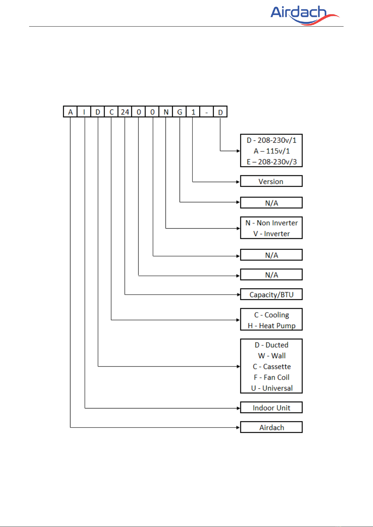
1. Nomenclature .................................................................................................................2
2. Model Names of Indoor/Outdoor Units .......................................................................4
3. External Appearance .....................................................................................................5
4. Features ..........................................................................................................................6
Part 2. Indoor Unit......................................................................................................7
Air Handler Type ........................................................................................................7
1. Features ..........................................................................................................................8
2. Specification....................................................................................................................9
3. Dimension .....................................................................................................................10
4. Service Space ..............................................................................................................11
5. Wiring Diagrams...........................................................................................................12
6. Electric Characteristics ...............................................................................................12
7. Exploded View..............................................................................................................13
8. The Specification of Wiring ........................................................................................15
9. Field Wiring...................................................................................................................16
10. Trouble shooting ........................................................................................................16
Part 3 Outdoor Unit..................................................................................................17
1. Specification .................................................................................................................18
2. Dimensions ...................................................................... Error! Bookmark not defined.
3. Service Space..................................................................................................................20
4. Wiring Diagrams ..........................................................................................................21
5. Electric Characteristics ...............................................................................................21
6. Operation Limits...........................................................................................................22
7. Sound Levels................................................................................................................22
8 .Exploded View .............................................................................................................22
9. Troubleshooting ...........................................................................................................25
Part 4 Installation.....................................................................................................36
1. Precaution on Installation ...........................................................................................37
2. Vacuum Dry and Leakage Checking ........................................................................38
3. Additional Refrigerant Charge ...................................................................................42
4. Insulation Work ............................................................................................................43
5.Test Operation...............................................................................................................45
Content

R410A 17.5 SEER Inverter Split System Technical Manual
1. Nomenclature
1.1 Indoor unit

R410A 17.5 SEER Inverter Split System Technical Manual
1.2 Outdoor unit

R410A 17.5 SEER Inverter Split System Technical Manual
2. Model Names of Indoor/Outdoor Units
2.1 Indoor Units
Model name
Dimension(H×W×D)
(inch)
Power supply
AIDH2400VG1-D
45-3/4 × 19-2/3 × 22
208~230V-1Ph-60Hz
AIDH3600VG1-D
45-3/4 × 19-2/3 × 22
208~230V-1Ph-60Hz
AIDH4800VG1-D
53 × 22 × 24-1/2
208~230V-1Ph-60Hz
AIDH6000VG1-D
53 × 22 × 24-1/2
208~230V-1Ph-60Hz
2.2 Outdoor Units
Model name
Dimension(H×W×D)
(inch)
Power supply
ACTH2418VG1-D
25 × 29-1/8 × 29-1/8
208~230V-1Ph-60Hz
ACTH3618VG1-D
25 × 29-1/8 × 29-1/8
208~230V-1Ph-60Hz
ACTH4818VG1-D
32-7/8 × 29-1/8 × 29-1/8
208~230V-1Ph-60Hz
ACTH6018VG1-D
32-7/8 × 29-1/8 × 29-1/8
208~230V-1Ph-60Hz

R410A 17.5 SEER Inverter Split System Technical Manual
3. External Appearance
3.1 Indoor unit
Air Handler
3.2 Outdoor unit
Top-discharge(Metal grill)
Note: Standard outdoor unit is using plastic grill. Metal grill can be customized.

R410A 17.5 SEER Inverter Split System Technical Manual
4. Features
4.1 Wide operation range, down to 10°F degree for heating.
4.2 Well-known brand inverter compressor, reliable quality.
4.3 Intelligent defrost programs, unit will choose different defrost program according to
real condition.
4.4 Condenser coils constructed with copper tubing and enhanced aluminum fins.
4.5 Use EXV (heating) and TXV(cooling) as expansion device;
4.6 Direct drive motors, 3-speed, provide selections of air flow to meet desired
applications.
4.7 24V control, time delay relay, fan relay and transformer included.
4.8 R410A environment friendly refrigerant.
4.9 AHRI certification, ETL certification.

R410A 17.5 SEER Inverter Split System Technical Manual
Part 2. Indoor Unit
Air Handler Type
1. Features.................................................................................. 8
2. Specification............................................................................ 9
3. Dimension…………………………………………………………10
4. Service Space....................................................................... 13
5. Wiring Diagrams.................................................................... 14
6. Electric Characteristics.......................................................... 14
7. Exploded View ...................................................................... 15
8. The Specification of Wiring ................................................... 17
9. Field Wiring ........................................................................... 16
10. Trouble shooting.................................................................. 16

R410A 17.5 SEER Inverter Split System Technical Manual
1. Features
(1) “A” shape coils, constructed with copper tubing and enhanced aluminum fins
(2) Direct drive motors,3 speed, provide selections of air flow to meet desired applications.
10” big fan, powerful wind. Motor is covered with thermal insulator, keep motor running in safety
status.
(4) Use TXV as expansion device(18 SEER air handler)
(5) Detachable air filter for cleaning or renewal
Versatile 4-way convertible design for vertical up airflow, horizontal right airflow.

R410A 17.5 SEER Inverter Split System Technical Manual
2. Specification
Model
AIDH2400VG1-D
AIDH3600VG1-D
AIDH4800VG1-D
AIDH6000VG1-D
Power supply
V/Ph/Hz
208-230V/1PH/60Hz
Cooling
Capacity
Btu/h
24000
34500
47000
56000
Minimum Circuit
Ampacity
A
17.7
24.2
31.9
36.5
Max. Overcurrent
Protection
A
30
40
50
60
SEER
17.5
17.5
17.5
17.5
Heating
Capacity
Btu/h
24000
34500
46500
55000
HSPF
9.5
9.0
9.5
9.5
Indoor coil
Number of rows
4×2
4×2
4×2
5×2
Tube outside dia. /
Type
in
0.28 inch / Inner groove tube
Fin spacing /
Thickness / Type
in. / in.
0.062 / 0.0037 / Hydrophilic aluminum
Tube pitch(a) ×
row pitch(b)
in
0.53 × 0.83
0.53 x 0.83
0.53 x 0.83
0.53 x 0.83
Indoor motor
Type
ECM
Rated HP
1/3
1/2
3/4
3/4
Rated RPM
r/min
770
870
1050
1120
FLA
2.8
4.1
6.0
6.0
Indoor fan
Material
Galvanized plate
Type
Centrifugal
Diameter
inch
11
11
11
11
Height
inch
10-5/8
10-5/8
10-5/8
10-5/8
Indoor air flow
CFM
830
1100
1500
1750
ESP
Pa
25
37.5
50
50
Indoor noise level
dB(A)
63
66
67
68
Metering
device
Throttle type
TXV
Model number
3TR
3TR
5TR
5TR
Electrical
Data
Voltage-Phase-Hz
V-Ph-Hz
208/230V 1Ph 60Hz
Minimum Circuit
Ampacity
3.5
5.1
7.5
7.5
Max. Overcurrent
Protection
15
15
15
15
Min / Max Volts
V
187 / 253
187 / 253
187 / 253
187 / 253
Dimension Unit
(H×W×D)
in.
45-3/4 × 19-2/3 × 22
53 × 22 × 24-1/2
Packing (H×W× D)
in.
47-3/5×22-7/8×25-3/5
54-3/4×25-1/8×28
Net / Gross weight
lbs.
126 / 139
126 / 139
170 / 188
170 / 188
Refrigerant piping Liquid side /
Gas side
in.
3/8 / 3/4
3/8 / 3/4
3/8 / 7/8
3/8 / 7/8
Notes:
1. Nominal cooling capacities are based on the following conditions:
Indoor temp: 80°FDB, 66°FWB; Outdoor temp: 95°FDB; Equivalent ref. piping: 5m (horizontal)
2. Nominal heating capacities are based on the following conditions:
Indoor temp: 68°FDB; Outdoor temp: 44°FDB, 43°FWB; Equivalent ref. piping: 5m (horizontal)
3. Actual noise level may differ, depending on the room structure, etc., since these noise values are from an
anechoic room.

R410A 17.5 SEER Inverter Split System Technical Manual
3. Dimension
Fig.1 DIMENSIONS
DIMENSIONAL DATA
MODEL
SIZE
Dimensions
UNIT
HEIGHT
"H"/in
UNIT
WIDTH
"W"/in
UNIT
LENGTH
"D"/in
SUPPLY
DUCT "A"/in
LIQUID LINE /
VAPOR LINE IN
24K
45-3/4
19-2/3
22
17.87
3/8'' / 7/8''
36K
45-3/4
19-2/3
22
17.87
3/8'' / 7/8''
48K
53
22
24-1/2
19.53
3/8'' / 7/8''
60K
53
22
24-1/2
19.53
3/8'' / 7/8''

R410A 17.5 SEER Inverter Split System Technical Manual
4. Service Space
The indoor unit should be installed in a location that meets the following requirements:
INSTALLATION NOTES:
1. Vertical up airflow: For the method of trapping or plugging all drains, see the pic on the left.
2.Horizontal right airflow: For the method of installation, see the pic on the right.
3. The seal-plugs are supplied as accessories and be screwed tightly only with hand.

R410A 17.5 SEER Inverter Split System Technical Manual
5. Wiring Diagrams
24K/36K/48K/60K
6. Electric Characteristics
Model
Indoor Units
Hz
Voltage
Min.
Max.
AIDC2400NG1-D
60
208-230V
198V
242V
AIDC3600NG1-D
60
208-230V
198V
242V
AIDC4800NG1-D
60
208-230V
198V
242V
AIDC6000NG1-D
60
208-230V
198V
242V

R410A 17.5 SEER Inverter Split System Technical Manual
7. Exploded View
No.
Part Name
Quantity
1
Filter Cover plate
1
2
Water pan components
1
2.1
Water pan# 1
1
2.2
Water pan# 2
1
2.3
Water pan fixed block
1
2.4
Water pan brace
2
3
Evaporator pre-welded assembly
1
3.1
Air header Assembly
1
3.2
Diverter Assembly
1
3.3
TXV
1
3.4
Connecting pipe
1
3.5
Evaporator
2
3.6
Evaporator Baffle
1
3.7
Evaporator baffle welded assembly
1
3.8
Evaporator Water Baffle #1
2

R410A 17.5 SEER Inverter Split System Technical Manual
3.9
Evaporator Water Baffle #2
1
3.10
Evaporator Water Baffle #3
1
3.11
Evaporator Fixing Plate #1
1
3.12
Evaporator Fixing Plate #2
1
3.13
Evaporator Junction Plate
1
4
Chassis assembly
1
5
Supporter
2
6.1
Right Volute Wind Wheel
1
6.2
Indoor Motor
1
7
Fan Motor Fixing plate assembly
1
7.1
Fan Motor Fixing plate
1
7.2
Wind Wheel Fixed Block
2
7.3
Fixed plate on air duct
1
7.4
Stator
2
7.5
air duct left stationary plate
1
7.6
air duct right stationary plate
1
8
Electronically Controlled Cover Plate Cotton Pasting Component
1
9
Electronic Control Components
1
9.1
Electronic Control Mounting Plate
1
9.2
Main Board
1
9.3
Transformer
1
10
Water pan supporter assembly
4
11
Upper side plate assembly
1
12
Pipe Cover plate assembly
1
13
Lower side plate assembly
1

R410A 17.5 SEER Inverter Split System Technical Manual
8. The Specification of Wiring
Note:
The cross-section areas of wires or lines should not be less than the corresponding ones listed
in the table below; Besides, if the power wires is quite long from the unit, please choose the
windings with larger cross-section area to guarantee the normal power supply.
Model
Type
Indoor power
wire diameter
Thermostat communication wire
diameter
Outdoor power
wire diameter
Indoor
Outdoor
AIDC2400NG1-D
Cooling &
heating
3*17Awg
4*18Awg
3*18Awg
3*14Awg
AIDC3600NG1-D
Cooling &
heating
3*17Awg
4*18Awg
3*18Awg
3*14Awg
AIDC4800NG1-D
Cooling &
heating
3*17Awg
4*18Awg
3*18Awg
3*12Awg
AIDC6000NG1-D
Cooling &
heating
3*17Awg
4*18Awg
3*18Awg
3*12Awg

R410A 17.5 SEER Inverter Split System Technical Manual
9. Field Wiring
1. To avoid the electrical shock, please connect the air conditioner with the ground lug.
The main power plug in the air conditioner has been joined with the ground wiring,
please don't change it freely.
2. The power socket is used as the air conditioner specially.
3. Don't pull the power wiring hard.
4. When connecting the air conditioner with the ground, observe the local codes.
5. If necessary, use the power fuse or the circuit, breaker or the corresponding scale
ampere.
10. Troubleshooting
The fault codes for indoor unit as follows:
Display mode
Status description
Green light always on
No system alarm and error, normal standby
Red light always on
Evaporator tube temperature sensor( T 2 ) failure
Green light always on, yellow light flashing
Evaporator high and low temperature protection
Green light flashing
system is in normal operating status

R410A 17.5 SEER Inverter Split System Technical Manual
Part 3 Outdoor Unit
1. Specification ...................................................................20
2. Dimensions.....................................................................21
3. Service Space.................................................................22
4. Wiring Diagrams .............................................................23
5. Electric Characteristics ...................................................23
6. Operation Limits..............................................................24
7. Sound Levels..................................................................24
8. Exploded View................................................................25
9. Troubleshooting ..............................................................27

R410A 17.5 SEER Inverter Split System Technical Manual
1. Specification
Model
ACTH2418VG1-D
ACTH3618VG1-D
ACTH4818VG1-D
ACTH6018VG1-D
Electrical
Data
Voltage-Phase-Hz
V-Ph-Hz
208/230V-1Ph-60Hz
Minimum Circuit
Ampacity
A
17.7
24.2
31.9
36.5
Max. Overcurrent
Protection
A
30
40
50
60
Min / Max Volts
V
187 / 253
187 / 253
187 / 253
187 / 253
Cooling
Capacity
Btu/h
24000
34500
47000
56000
EER
Btu/h.W
11.6
11.6
11.6
11.2
SEER
Btu/h.W
17.5
17.5
17.5
17.5
Heating
Capacity
Btu/h
24000
34500
46500
55000
HSPF
Btu/h.W
9.5
9.0
9.5
9.5
Compressor
Model
ATM240D57UMT
ATM240D57UMT
MNB42FCKMC-L
MNB42FCKMC-L
Brand
GMCC
GMCC
Mitsubishi
Mitsubishi
Type
Twin-rotary DC
Twin-rotary DC
Twin-rotary DC
Twin-rotary DC
Capacity
W/h
7130±5%
7130±5%
13780±5%
13780±5%
Input
W
2200±5%
2200±5%
4040±5%
4040±5%
Rated current
(RLA)
A
9.7
9.7
11.80
11.80
Refrigerant oil
oz
29.42
29.42
47.34
47.34
RLA
13.5
13.5
27.2
27.2
LRA
45
45
58.1
58.1
Outdoor
motor
Model
YDK-110-8P2-AL
YDK-110-8P2-AL
WZDK200-310G
WZDK200-310G
Brand
Chigo
Chigo
Panasonic
Panasonic
Type
AC
AC
DC
DC
Rated HP
W
1/6
1/6
1/3
1/3
Capacitor
μF
6
6
/
/
Speed
rpm
40
40
60
60
FLA
A
0.8
1
2.5
2.5
Outdoor Fan
Material
Metal
Type
Axial flow
Diameter
in.
23-5/8
23-5/8
23-5/8
23-5/8
Height
in.
2-3/4
4-1/2
4-1/2
4-1/2
Air flow
CFM
2950
2950
4100
4100
Outdoor coil
Number of row
1
2
2
2
Tube outside dia
in
9/32
9/32
9/32
9/32
Outdoor noise level
dB(A)
75
77
79
79
Outdoor unit
Dimension
(H×W×D)
in.
24-15/16×29-1/8×29-1/8
32-7/8×29-1/8×29-1/8
Packing (H×W×D)
in.
26-1/4×30-1/5×30-1/5
34-1/2×30-1/5×30-1/5
Net / Gross weight
lbs.
157 / 165
157 / 165
201 / 211
201 / 211
Refrigerant
system
Liquid side / Gas
side
in.
3/8 / 3/4
3/8 / 3/4
3/8 / 7/8
3/8 / 7/8
Factory charge
R410A
oz
114
114
166
166
Metering device
EEV
EEV
EEV
EEV
Max. refrigerant
pipe length
Ft
100
100
100
100
Max. difference in
level
Ft
50
50
50
50
This manual suits for next models
7
Table of contents
Popular Inverter manuals by other brands

SOLIS
SOLIS S5 Series user manual

HEIDENHAIN
HEIDENHAIN TNC 410 M Technical manual

WEG
WEG CFW300 Quick installation guide

enphase
enphase IQ Combiner 4 Quick install guide

CMP
CMP PowerClean Salt Econ INSTALLATION INSTRUCTIONS & PRODUCT MANUAL

Power One
Power One AURORA PVI-STRINGCOMB Installation and instruction manual