AiRide WR17602632 User manual

INSTALLATION INSTRUCTIONS
10-23
firestoneairide.com
2632

1 firestoneairide.com
IMPORTANT
PLEASE DON’T HURT YOURSELF, THE KIT, OR YOUR VEHICLE. TAKE A MINUTE TO READ THIS IMPORTANT INFORMATION.
SAFE INSTALLATION
Please take all safety precautions during installation. A hydraulic jack can fail, and if that happens, you can be
seriously hurt, or worse, if you are relying on it to hold up the vehicle. If you use a hydraulic jack, secure jack
stands in the appropriate locations and chock any tires still touching the ground.
Wear safety glasses or goggles.Your eyes may be lower than some parts and pieces, and you don’t want to losean eye.
Remove the possibility of any electrical issues by disconnecting the negative battery cable.
VEHICLE GVWR
NEVER exceed the maximum load recommended by the vehicle manufacturer (GVWR).The GVWR can be found
in your vehicle’s owner’s manual or on the data plate on the driver’s side door. Consult your local dealership for
additional GVWR specifications.
PRESSURE TO LOAD
Be sure to review the load limits noted in the Air Spring Kit Installation Instructions (sold separately).
APPROPRIATE AIR PRESSURE
For best ride, use only enough air pressure in the Air Springs to level the vehicle when viewed from the
side (front to rear).This will vary, depending on the load, location of the load, condition of the existing
suspension, and personal preference.
ONCE INSTALLED SUCCESSFULLY, FOLLOW THE PRESSURE REQUIREMENTS FOR THE AIR SPRINGS.
FOR FIRESTONE, GENERALLY:
305 1005
COIL-RITE RIDE-RITE

2632 Installation Instructions 2
PARTS
Compare the parts below to your kit. Assure you have all pieces, and organize them for an easier installation.
MAIN KIT CONTENTS
PT # 9965
The 9961 ECU and
9962 Wire Harness
are packaged
inside one box
under the 9965
part number.
PT # 9961
x 1 ECU
PT # 9523
x 1 AIR COMPRESSOR
KIT
PT # 9962
x 1 WIRE HARNESS
PT # 9415
x 1 AIR TUBING
(22 FEET)
A21-760-2632 HARDWARE PACK
PT # 3087
x 4 10-32 x 1"
MACHINE SCREW
PT # 3093
x 2 10-32 x 3/4"
MACHINE SCREW
PT # 3086
x 10 #10 FLAT WASHER
PT # 3088
x 6 10-32 NYLOCK NUT
PT # 3421
x 1
10-16 x 3/4"
SELF-TAPPING
SCREW
PT # 9483
x 1
INFLATION VALVE
MOUNTING
BRACKET
PT # 3055
x 1
1/8 NPT PUSH-
TO-CONNECT
STRAIGHT FITTING
PT # 3025
1/4 PUSH-
TO-CONNECT TEE
PT # 3032
x 2
INFLATION VALVE
AND VALVE CAP
ASSEMBLY
PT # 9488
PT # 0899
PT # 9036
x 4 LARGE NYLON TIE x 2 THERMAL SLEEVE x 15 RED NYLON TIE
PT # 9968
x 1 AIR COMMAND
DUAL REMOTE

3 firestoneairide.com
CONTENTS AND OVERVIEW
PAGE 4PLANNING THE
INSTALL
PAGE 5PREPARE THE AIR
COMPRESSOR
PAGE 6DRILL HOLES FOR
AIR COMPRESSOR
AND ECU
PAGE 7INSTALL THE
AIR COMPRESSOR
AND ECU
PAGE 8INSTALL THE
AIR TUBING
PAGE 9INSTALL THE
WIRE HARNESS
PAGE 10 INSTALL THE
AIR FILTER AND
CLEAN UP
PAGE 11 ECU POWER UP/
APP PERFORMANCE
PAGE 13 USING THE
AIR COMMAND™
DUAL APP
* As a water/debris
trap. See page 4.
Create
loop in Air
Tubing.
AIR FITTING
AIR FILTER
9961 ECU
AIR SPRINGS
(sold separately)
3055 1/8 NPT PUSH-TO-CONNECT
STRAIGHT FITTING
AIR TUBING
AIR TUBING
BLACK
(GROUND)
RED (+)
30 AMP
IN-LINE FUSE
RED (+)
RED/WHITE
8-PIN ECU
CONNECTOR
(COMPRESSOR)
BATTERY (+)
YELLOW
(NOT USED)
LEFT AIR SPRING
(when facing forward)
RIGHT AIR SPRING
(when facing forward)
9962 WIRE
HARNESS
9523 AIR
COMPRESSOR
* As a water/debris
trap. See page 4.
Create
loop in Air
Tubing.
Route AUX
and EXH to
dry location.
BLACK (-)
BATTERY (-)
AIR TUBING
PAGE 15 QUICKSTART GUIDE
AIR COMMAND™
DUAL REMOTE
PAGE 19 TEST THE SYSTEM
PAGE 20 FIX AN AIR LEAK

2632 Installation Instructions 4
PLANNING THE INSTALL
THESE PLANNING STEPS WILL HELP YOU SAVE TIME AND WILL MAKE THE INSTALLATION EASIER.
DETERMINE THE MOUNTING LOCATION FOR THE AIR COMPRESSOR
- Provides ample air flow and is protected from airborne debris and moisture.
-
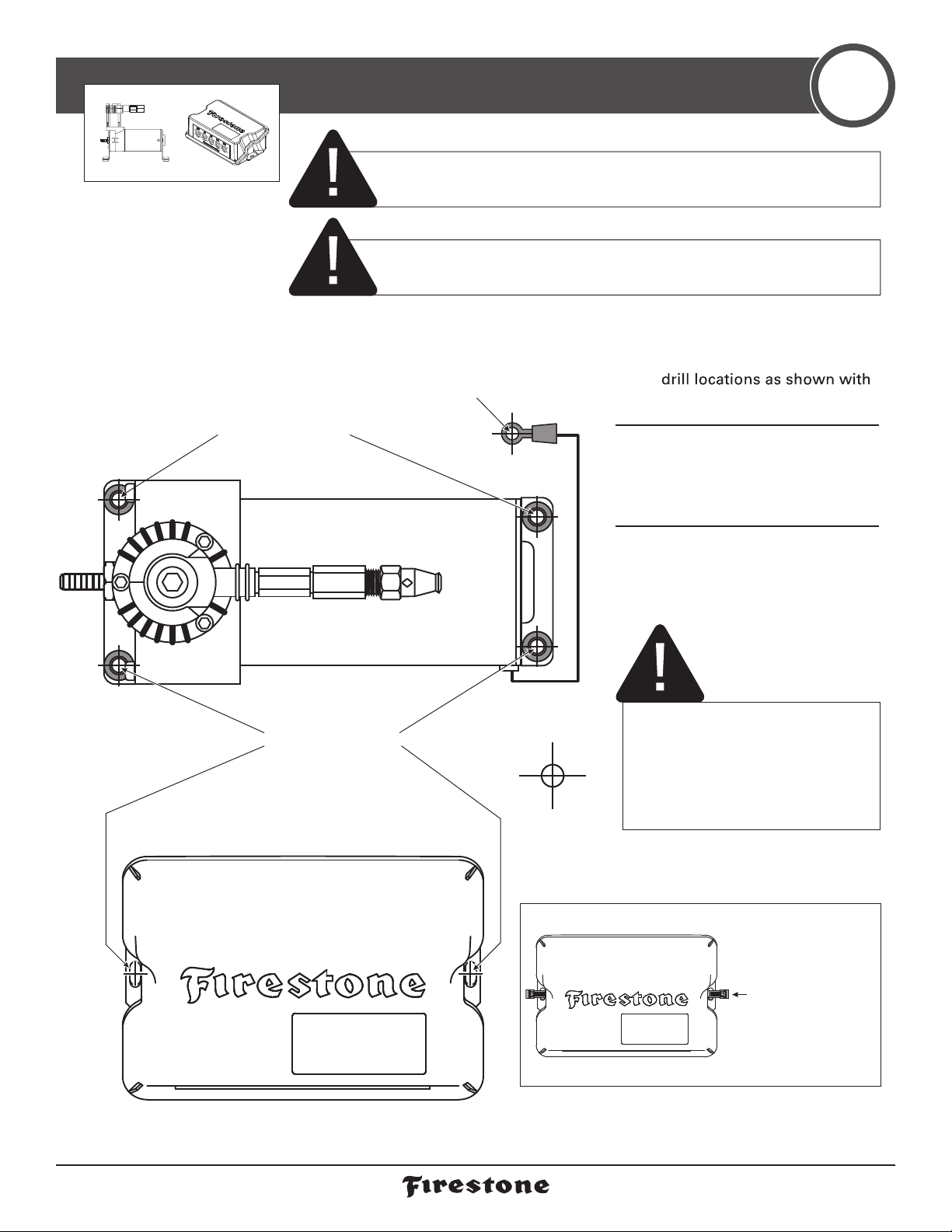
If using the optional Firestone Air Accessory Mounting Kit, consider the
guidelines above, and follow the kit’s instructions.
DETERMINE THE MOUNTING LOCATION FOR THE ECU
- Mount close enough to the Air Compressor to allow Wire Harness
connections to reach.
- Allow room for Air Tubing to connect to the Air Fittings on the ECU.
- Allow room for the Air Tubing to run without sharp curves or bends.
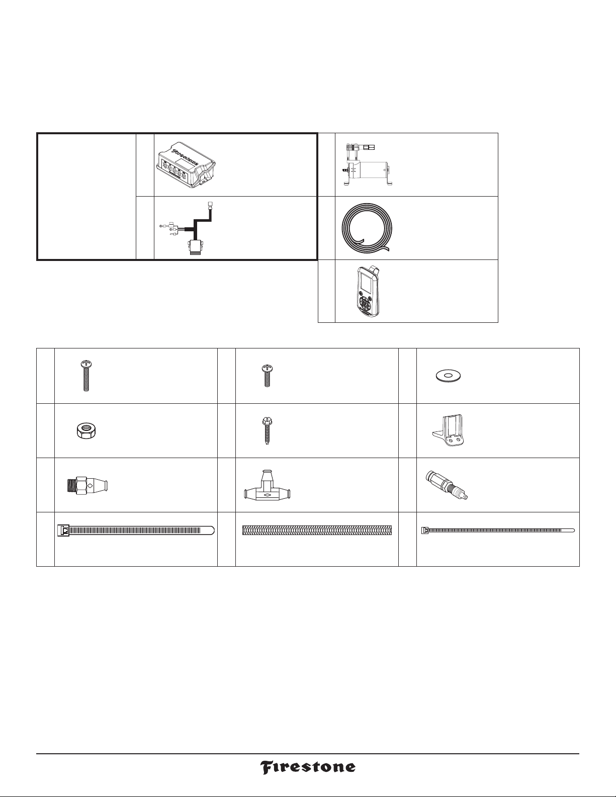
- Using supplied fasteners shown in Step 3 is recommended. If no other mounting option is available,
see the sidebar on Step 2 for using the Large Nylon Ties.
- Select a location that is solid and secure on the body or frame of the vehicle, away from any moving parts,
electrical or any other lines.
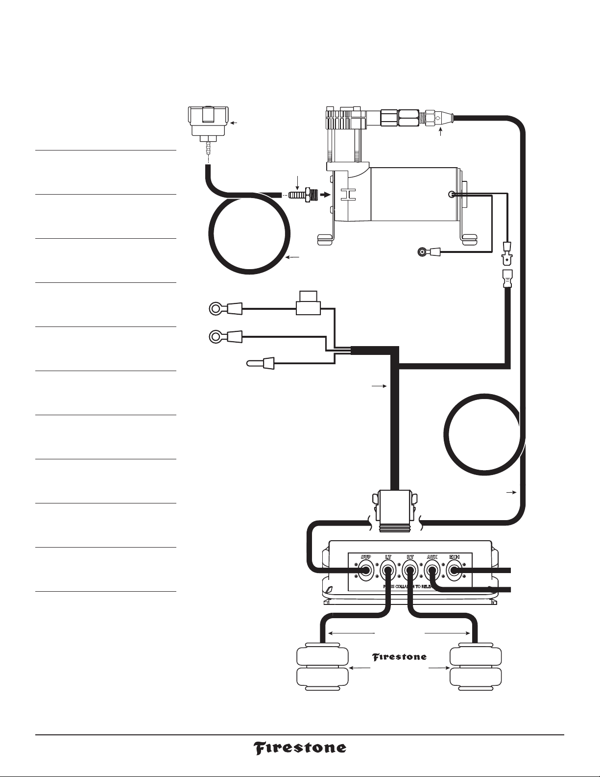
PLAN INSTALLATION ROUTES FOR WIRING AND AIR LINES
- Use supplied Thermal Sleeves on Air Tubing when routing near heat sources.
- Use supplied Nylon Ties to secure Air Tubing and Wire Harness to the vehicle.
- Make a loop in the Air Tubing where shown.This creates a water/debris trap that protects the Air Compressor.
- Measure twice, cut once!
TAPE ALL ELECTRICAL CONNECTIONS
- Use electrical tape to appropriately secure and protect all electrical connections.
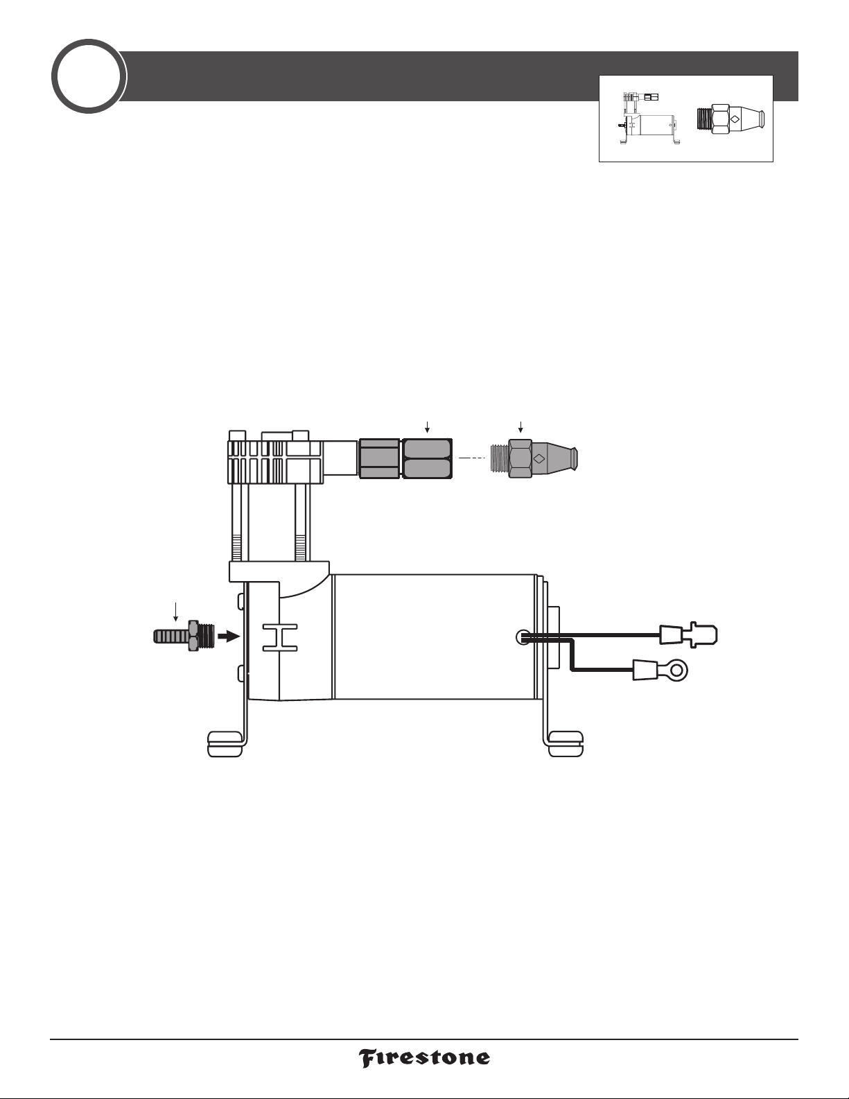
USING PUSH-TO-CONNECT FITTINGS FOR AIR LINES
Your kit includes Push-to-Connect fittings to connect the Air Tubing to hardware.
Use the instructions below when using the Air Tubing.
1Insert end of Air
Tubing into
Air Fitting. 2Push Air Tubing
into Air Fitting as
far as possible. 3Gently pull on
the Air Tubing
to check for a
secure fit.
4To remove, push
down collar and
gently pull Air
Tubing away.
Removal Tip: Use a 1/4 , 5/16 ,
or 6mm open-ended wrench
to push the collar down.
- Allow room for the 8-pin ECU connector to connect to the ECU.
- Mount close enough to the ECU to allow Wire Harness connections to reach.
- Make sure the Wire Harness and Air Tubing are not exposed to sharp metal edges that can damage them.

5 firestoneairide.com
9523 AIR COMPRESSOR
3055 1/8 NPT PUSH-TO-CONNECT
STRAIGHT FITTING
Tighten to engage two threads
of thread lock.
PRE-INSTALLED
CHECK VALVE
AIR FITTING
PREPARE THE AIR COMPRESSOR
1
NOTE: Air Compressorcan be mounted facing any direction.
1Install 1/8 NPT Push-to-Connect
Straight Fitting on the Check Valve.

2632 Installation Instructions 6
9523 AIR COMPRESSOR
BLACK
GROUND
WIRE
Use as template to
mark drill locations.
Drill within reach of the ground wire ring terminal on body or frame
of vehicle or create a wire to link to the negative battery terminal.
Minimum gauge of wire should be 12.
AIR ACCESSORY MOUNTING KIT CANNOT BE USED AS A
GROUNDING LOCATION FOR THE AIR COMPRESSOR.
Use as template to
mark drill locations.
9961 ECU
If there is no other
mounting option,
use at least two
Large Nylon Ties
to secure ECU
to the location
determined in
planning the
install section.
9961 ECU
DRILL HOLES FOR AIR COMPRESSOR AND ECU 2
7/32"
IF YOU ARE USING THE OPTIONAL FIRESTONE AIR ACCESSORY MOUNTING
KIT, SKIP THIS STEP AND REFERTOTHE MOUNTING KIT’SINSTRUCTIONS.
CHECK SURROUNDING AREA AND BACK SIDE OF MOUNTING LOCATION
TO AVOID DRILLING INTO EXISTING LINES OR WIRING.
1Using the Air Compressor
and ECU as templates, mark
a punch or marking tool.
2Mark Air Compressor
ground wire fastening
location within reach of the
ground wire ring terminal.
3Drill 7/32" diameter holes.
Remove any burrs and
debris from drill holes.
ASSURE THAT YOU INSTALL THE
AIR COMPRESSOR AND ECU CLOSE
ENOUGH SO THE CONNECTORS ON
THE WIRE HARNESS WILL REACH
THEM BOTH.
OPTIONAL ECU MOUNTING

7 firestoneairide.com
3093 10-32 x 3/4” MACHINE SCREW
3086 #10 FLAT WASHER
3088 10-32 NYLOCK NUT
3086 #10 FLAT WASHER
(or optional Firestone
Air Accessory
Mounting Kit).
BODY OR FRAME
OF VEHICLE
MOUNTING HOLES
9961 ECU
9961 ECU
INSTALL THE AIR COMPRESSOR AND ECU
3
x 12x 2x 4 x 6
DO NOT OVER TIGHTEN MOUNTING BOLTS AND NUTS ON THE AIR COMPRESSOR.
TOO MUCH TORQUE CAN CRUSH THE BRASS INSERTS AND RUBBER ISOLATORS.
1Mount the Air Compressor
to the drill hole location
using the suppliedfasteners.
DO NOT OVERTIGHTEN.
2Mount the ECU to the drill
hole location using the
supplied fasteners. 3Mount the black ground wire
ring terminal using the sup-
plied fasteners. Assure that
the ring terminal makes
a solid contact with bare
metal for a proper ground.
3093 10-32 x 3/4” MACHINE SCREW
3086 #10 FLAT WASHER
3088 10-32 NYLOCK NUT
3086 #10 FLAT WASHER
(or optional Firestone
air accessory
mounting kit).
BODY OR FRAME
OF VEHICLE
MOUNTING HOLES
9961 ECU
9961 ECU
TOP VIEW
9523 AIR
COMPRESSOR
Air Accessory Mounting
Kit cannot be used
as a grounding
location for the
Air Compressor.
NOTE: You may want to
combine other grounds
to this mounting location.
(or optional Firestone
Air Accessory
Mounting Kit).
3087 10-32 x 1”
MACHINE SCREW
3088 10-32 NYLOCK NUT
3086 #10 FLAT WASHER
3088 10-32
NYLOCK NUT
3086 #10 FLAT
WASHER
3421 10-16 x 3/4”
SELF-TAPPING SCREW
BLACK
GROUND
WIRE
BODY OR FRAME
OF VEHICLE
BODY OR FRAME
OF VEHICLE

2632 Installation Instructions 8
INSTALL THE AIR TUBING 4
9961 ECU
AIR SPRINGS
(sold separately)
AIR TUBING
AIR TUBING
LEFT AIR SPRING
(when facing forward)
RIGHT AIR SPRING
(when facing forward)
* As a water/debris
trap. See page 4.
Create
loop in Air
Tubing.
Route AUX
and EXH to
dry location.
3055 1/8 NPT PUSH-TO-CONNECT
STRAIGHT FITTING
9523 AIR
COMPRESSOR
DO Make sure the cut is as square as possible.
Use a tube cutter or very sharp utility knife. DON’T Fold or kink the AirTubing.
Cut the AirTubing at an angle.
Use pliers, scissors, snips,
saws, or side cutters.
Square cut
90˚
AIR TUBING AIR TUBING AIR TUBING AIR TUBING
PROPER AND IMPROPER CUTS IN THE AIR TUBING
EXHAUST ALL AIR FROM THE SYSTEM PRIOR
TO RELEASING AIR TUBING FROM AIR FITTINGS. 5
PSI
1Route the Air Tubing from
1/8 NPT Push-to-Connect
Straight Fitting on the top
of the Air Compressor to
the Supply (SUP) Air Fitting
on the ECU, leaving room
to secure it safely. Use the
guidelines on page 4 for
proper Push-to-Connect
Straight Fitting install.
2Repeat Step 1 to route Air
Tubing from the ECU to the
Air Springs. Use the RT and
LT Air Fittings on the ECU.
3Install AirTubing to the
Exhaust (EXH) Air Fitting to
reduce exhaust noise and
prevent dirt from clogging
the port (recommended
for off-road or dirty environ-
ments). Do not exceed 16" of
AirTubing, and secure it so
the end turns to the ground.

9 firestoneairide.com
INSTALL THE WIRE HARNESS
5
9961 ECU
BLACK
(GROUND)
RED (+)
30 AMP
IN-LINE FUSE
RED (+)
RED/WHITE
8-PIN ECU
CONNECTOR
(COMPRESSOR)
BATTERY (+)
YELLOW
(NOT USED)
9962 WIRE
HARNESS
9523 AIR
COMPRESSOR
BLACK (-)
BATTERY (-)
1Route the Wire Harness in
the mostprotected manner
possible, and securely make
allconnectionsas shown.
Why ground the Wire
Harness to the battery?
The ECU needs a good,
clean ground for opti-
mal accuracy. The Air
Compressor can ground
to the frame, but the
ECU cannot.
RED LED GREEN LED
9961 ECU
LEDs off – ECU off
Red LED flashing – Errors are present
Green LED flashing – Bluetooth not
connected, normal operation
Green LED solid – Bluetooth connected,
Normal operation
ECU INDICATOR LIGHTS (Inside Case)

2632 Installation Instructions 10
9523 AIR COMPRESSOR
AIR TUBING
FROM AIR COMPRESSOR KIT
AIR FILTER
Create
loop in Air
Tubing.
FILTER LIFE WILL VARY BASED ON ENVIRONMENTAL CONDITIONS.
PROTECT THE AIR COMPRESSOR BY CHANGING THE AIR FILTER
MORE FREQUENTLY IN DUSTY CONDITIONS.
INSTALL THE AIR FILTER
CLEAN UP INSTALLATION
6
7
1Clean up the installation using
supplied NylonTies, and return
all factory parts and materials
to operative state.
USING SUPPLIED NYLON TIES, SECURE ALL
WIRING AND AIR TUBING IN A MANNER
THAT DOES NOT OBSTRUCT MOVING PARTS
OR IN ANY WAY THAT AFFECTS YOUR ABILI-
TY TO SAFELY OPERATE THE VEHICLE.
1Fully secure the Air Filter
barb into the AirTubing from
the Air Compressor Kit. 2Press AirTubing onto
the barb on the Air Com-
pressor Air Fitting until
fully seated. Assure you cre-
ate a loop in the AirTubing,
as shown, when securing it
to the vehicle.
3Periodically check the Air
Filter during operation.
When the Air Filter is dirty
and needs to be replaced,
contact an Authorized
Firestone dealer to
purchase a new one.

11 firestoneairide.com
ECU POWER UP/APP PERFORMANCE
8
1Download app from Google Play or Apple
Store. Search for ‘Air Command Dual’.
2Start the vehicle and open app.
3Select SCAN and click on the ECU
from the screen.
4Follow onscreen prompts to link to the
ECU and press NEXT.
5Default passkey is 123456.

2632 Installation Instructions 12
ECU POWER UP/APP PERFORMANCE
6FACTORY RESET
(TROUBLESHOOTING ONLY)
• Remove fuse from red wire by battery or
remove wire harness connector from ECU
• Remove app from phone
• Reinstall fuse or plug wire harness
connector back into the ECU
• Download the app
The ECU will remain active for two hours
after initial installation or factory reset.
After voltage drop due to engine
stop, the ECU will remain active for up
to thirty minutes.
9961 ECU
A SOLID GREEN LED
ON THE ECU INDICATES
BLUETOOTH IS CONNECTED
OVER THE AIR FIRMWARE UPDATE
If an OTA update is available, a popup will appear on the app to activate.
After voltage drop due to engine stop, the ECU will remain active for five minutes.
• If you select SKIP, the firmware can be updated once connected to the app
• If you select INSTALL, the firmware will begin to update.This will take approximately 3-4 minutes
• Keep the app open during the update and stay within range of the ECU until complete
• Once OTA is complete, restart the app, use the default passkey, and use as normal

13 firestoneairide.com
USING THE AIR COMMAND™DUAL APP
9
SETTINGS ICON
TOGGLE TANK MODE ON/OFF
COMPRESSOR OFF
COMPRESSOR ON
CHANGE UNITS
TURN TANK MODE ON/OFF,
SET PRESSURES FOR TANK
MODIFY MEMORY PRESSURES AND NAMES
CONTROL AUX PRESSURES
VERIFIES SYSTEM ISSUE WITH
TROUBLESHOOTING STEPS
SHOWS SYSTEM INFORMATION
BLUETOOTH SETTINGS
CONTACT
OVER-THE-AIR UPDATE FOR THE ECU
USED FORTROUBLESHOOTING THE SYSTEM
SELECT MEMORY 1 OR 2
CHANGE MEMORY NAME
SELECT FOR CURRENT SYSTEM SETTINGS
(AUTOFILL)
MODIFY MEMORY PRESSURES
MEMORY BUTTONS
(Tap to activate)
INCREASE PRESSURE
(Tap to activate)
TARGET PRESSURE
(Tap to activate)
DECREASE PRESSURE
(Tap to activate)
ACTUAL PRESSURE
MAIN SCREEN
TANK SETTINGS
SETTINGS
MEMORY SETTINGS
TANK MODE
SHOULD NOT BE
USED IN THIS KIT.

2632 Installation Instructions 14
USING THE AIR COMMAND™DUAL APP
SLIDE TO MANUAL AND SYSTEM
WILL FILL UNTIL TURNED OFF
SHOWS SYSTEM INFORMATION
GREEN INDICATES
WHAT PART IS ON
VEHICLE BATTERY VOLTAGE
INDICATES SYSTEM FAULT
CLARIFIES INDICATOR CODE
ALLOWS USER TO CLEAR
AND ACKNOWLEDGE
SLIDE TO AUTO AND SET PRESSURE
ACTUAL PRESSURE
AUXILIARY SYSTEM FAULT
DIAGNOSTICS
AUXILIARY MODE
SHOULD NOT BE
USED IN THIS KIT.

15 firestoneairide.com
AIR COMMAND DUAL REMOTE QUICKSTART GUIDE
10
1FUNCTIONS OF REMOTE BUTTONS
2HOME SCREEN LAYOUT
Set or Select
Memory 2
Select Right
Air Spring/
Move Right
Set or Select
Memory 1
Select Left
Air Spring/
Move Left/
Exit Menu
Enter Menu/
Select Button
Increase
Pressure/
Move Up
Decrease
Pressure/
Move Down
USB-C Charging
Port
Visor Clip
Wireless Signal
Strength
Current Pressure
Reading for Left Air
Spring
Remaining
Battery Level
Tank Pressure
Current Pressure Reading
for Right Air Spring
Memory 2 Settings for
Air Springs
Memory 1 Settings for
Air Springs
Set Pressure Target for
Right Air Spring
Set Pressure Target
for Left Air Spring
Pressure Units
Tank Mode Active
Error Indicator
Arrow Indicators Set to Left,
Right, or Both when Adjusting
Target Pressure
™

2632 Installation Instructions 16
AIR COMMAND DUAL REMOTE QUICKSTART GUIDE
Initial Connection
Each remote is tested and
paired with an ECU prior to
shipping to make sure it
functions correctly. Expect
to see that an ECU is not
found when first turning on
the remote.
Move to and enter the ‘Scan
New’ function to find your
ECU.
Device Scan
This page shows all ECUs
found when a new scan is
complete. To make initial
startup easier, only have
one ECU powered on at a
time. The first ECU found
will automatically be
selected and highlighted at
the top of the screen. Press
the F-sheild Button to
connect to that ECU.
Enter Passkey
The connection process
requires a Passkey to pair
with the ECU. The default
Passkey is 123456.
If the ECU has been
connected to a phone app
double check that the
Passkey is the same as on
the app. The remote will ask
for a different Passkey if
incorrect. Once successful,
the remote will return to the
home screen.
Change Passkey
It is possible to change the
remote passkey in the menu
settings shown on the next
page.
*Remember, the default
passkey is 123456.
Connection
Shows if the remote is
connected to the system.
*Not Found is usually
caused by the system not
having power.
*Not Connected is usually
caused by an incorrect
Passkey. It has found the
unit, but cannot connect.
Device Scan Continued
If no ECU is found, none will
be selectable to connect to.
If that is the case, please
make sure power is getting
to the ECU.
If the ECU has a green LED
flashing the power is on, but
no connection has been
made. Once connected the
LED should be stop flashing
but stay green.
12
3 4
5 6
3CONNECTING TO AN ECU
™

17 firestoneairide.com
AIR COMMAND DUAL REMOTE QUICKSTART GUIDE
4MENU SCREEN
5ADDITIONAL FEATURES
Menu
Pressing the center F-Shield
Button provides access to the
remote menu. All additional
settings are available here.
Use the Up and Down
Arrow Buttons to navigate the
menu. Press the Left Arrow
to exit to the Home Screen.
Tank Mode
Check when a tank is
connected to the air spring
system.
Minimum pressure must be
greater than pressure in the
air springs.
Maximum pressure can be
set at most 40 PSI greater
than minimum pressure.
Automatic Mode is only
available when Tank Mode is
not active. Set desired target
pressure and compressor will
run until pressure is met or it
has ran for 60 seconds. It can
be ran multiple times if needed.
Units
Select pressure
unit of measure.
PSI - Imperial
KPA - Metric (SI)
BAR - Metric
Manual Mode, when
selected, will run the
compressor until the user
presses the stop button.
Measured pressure is
shown on the left.
Auxiliary Port
™
TANK MODE
SHOULD NOT BE
USED IN THIS KIT.
AUXILIARY MODE
SHOULD NOT BE
USED IN THIS KIT.

2632 Installation Instructions 18
AIR COMMAND DUAL REMOTE QUICKSTART GUIDE
Errors
Error codes help diagnose issues with the physical
system. These codes identify pressure leaks, inflation
issues, wiring problems, etc. Refer to the troubleshooting
guide in the manual provided in the Air Command Kit for
working through initial common issues.
Once the issue is resolved make sure to clear the errors.
This will also reset (remove) the error indicator from the
top right of the screen and allow the system to operate
normally.
If these codes or system issues persist, please reach out
Diagnostics
This page shows current
operation of all air valves
and compressor states (on
or off) and the battery
voltage coming into the
ECU.
Hour Meters
This page shows how long
the ECU, compressor, and
air valves have operated
since the system was
installed.
About
This page provides the
current Firmware and
Hardware information for
both the Remote and ECU.
Display Mode
The Air Command Dual
Remote comes standard
with Dark Mode activated.
The use has the ability to
change between more or
less LEDs lit depending on
preference and ambient
conditions.
6DATA ANALYTICS
™

19 firestoneairide.com
TEST THE SYSTEM
11
With the Air Command™Dual App and your Air Springs installed, you are readyto testthe system.
NO LEAKS?
Congratulations!You’re riding right with the push of a
button! Remember to review the Operating Instructions.
LEAK?
Bummer. Continue to Step 12 to fix the leak.
1Reattach the negative
battery cable.
2Turn on your vehicle’s ignition.
4Spray fittings with
soap and water mixture
or glass cleaner. 5Observe bubbles.
3Use the Air Command™Dual App
or Dual Remote to inflate the
Air Springs to 70 PSI.
See Step 9 or 10 for details.
70
PSI
WATER
+
SOAP
SMALL SOAP BUBBLES
THAT DO NOT EXPAND
SOAP BUBBLES
THAT EXPAND
This manual suits for next models
1
Table of contents