Pellet/Corn Stove
Venting System
Installation Guide
UL 641 Listed
Important Installation and Operation Notes
oInspect each component for damage before installing;
rectify damage product claims through your retailer.
oConsult local building codes or fire officials about
restrictions and necessary inspections in your area.
oThe AirJet Pellet/Corn Stove Venting System is
designed and approved for the venting of listed pellet
stoves and gas and oil furnaces that do not exceed
570° F at the outlet.
oThis system is intended to form a continuous passage
from the appliance to above the roof line, including
the chimney cap.
oTo comply with UL Listings and the AirJet warranty,
use only the chimney parts defined by these instruc-
tions.
oUse the AirJet chimney cap on all installations to pre-
vent back drafts and to keep out rain and other debris.
oThis system provides for a continuous conduit of flue
gases through a double-walled construction with
stainless steel lining and galvanized exterior. You can
further enhance the life of system by coating all exte-
rior metal with high-temperature, rust-proof paint.
oMaintain a 3-inch minimum clearance to combustibles
when passing through walls, ceilings, or roofs. Always
use a Firestop when penetrating a wall or ceiling.
oCombustible material includes all material surfaced in
wood, paper, plant fibers, plastics and related material.
Such material is considered combustible even if it is
classified as flame proof or fire retardant, or has been
plastered.
oFor vertical installations, the maximum height is 60
feet; use a support at 30 feet.
oAn increaser may be used at any point in the system to
meet the requirements of the appliance manufacturer.
oIn considering the path of the venting system, care-
fully evaluate the support structures of your home or
building to avoid or minimize passing through these
structures.
oIf fly ash leakage occurs, seal the associated casing
joints with a silicone-based sealer rated at 400° F or
higher.
Model LC
Type L Vent
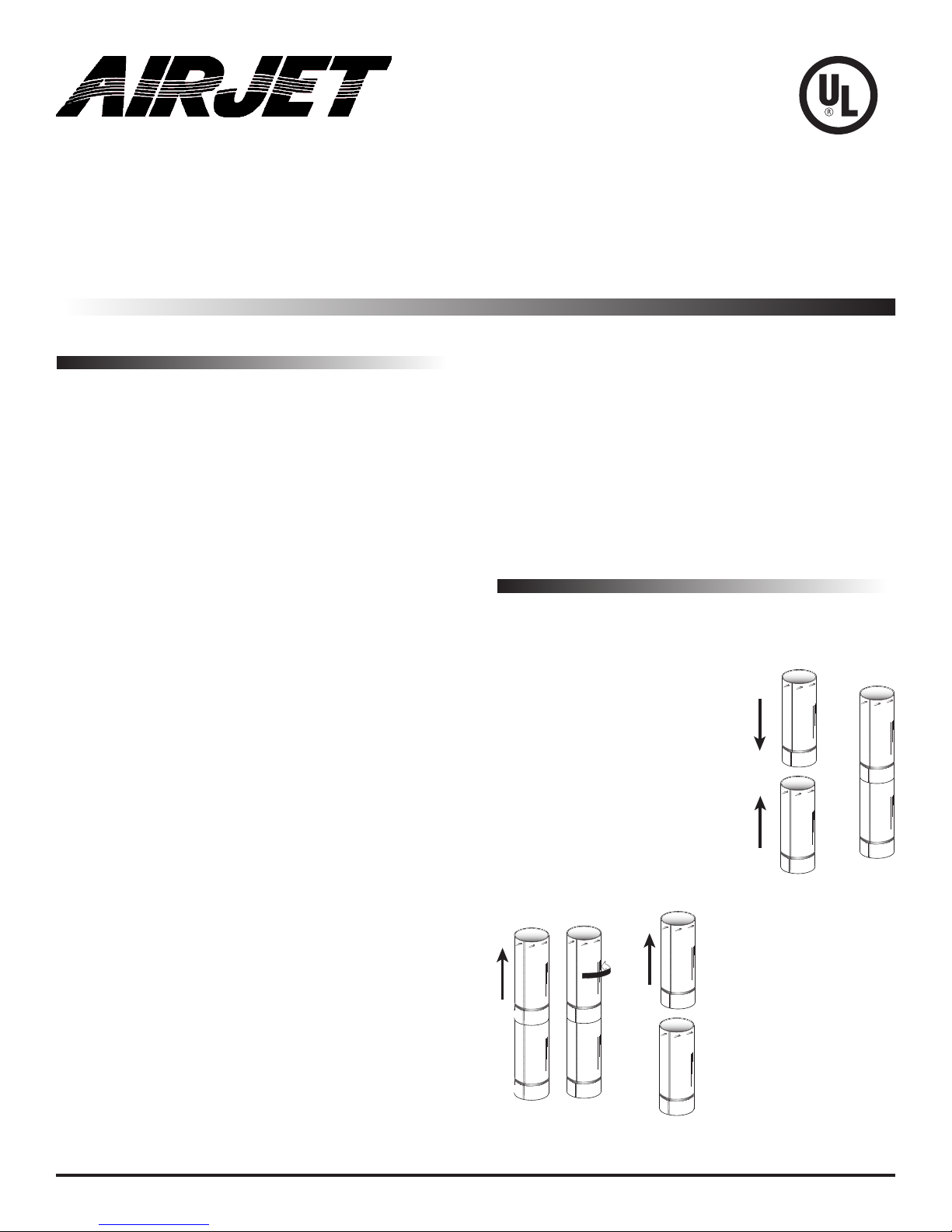
Using the AirJet “Snap-Lock” System
Our unique system makes assembly and disassembly a
snap!
Assembly
1. With male ends up, align the
seams.
2. Push the pieces straight together
until they “click.”
Note: No twisting is needed. It may
be helpful to place one piece on
the floor and snap the other on top.
Disassembly
1. Pull up on top piece to
fully engage the locks.
2. Twist the top piece coun-
ter-clockwise and pull up.
Illustration 1
Illustration 2
Page 1


