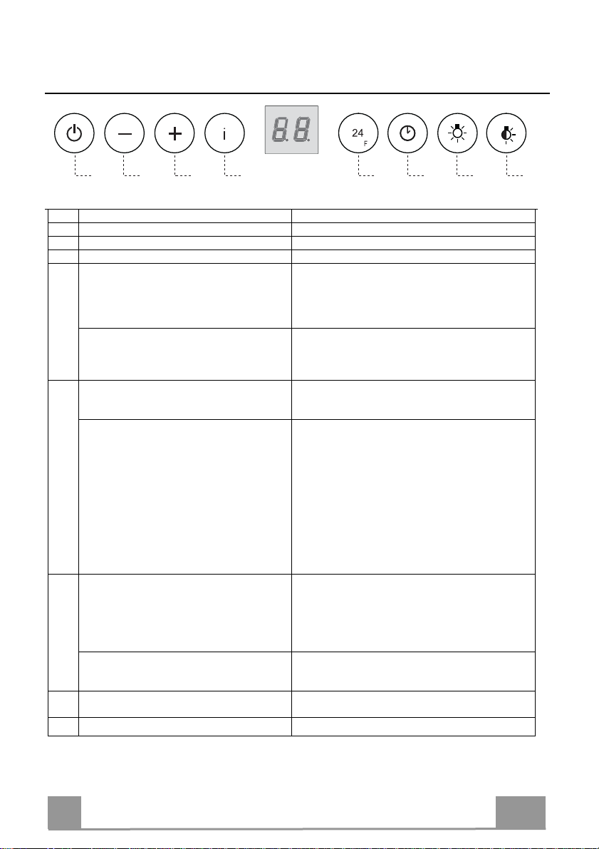
Award PPS902SI User manual

Instructions Manual
PPS902SI

2
2
INDEX
RECOMMENDATIONS AND SUGGESTIONS..................................................................................................................... 3
CHARACTERISTICS.............................................................................................................................................................6
INSTALLATION...................................................................................................................................................................... 7
USE........................................................................................................................................................................................ 9
MAINTENANCE...................................................................................................................................................................10
EN

EN 3
3
RECOMMENDATIONS AND SUGGESTIONS
The Instructions for Use apply to several versions of this appliance.
Accordingly, you may find descriptions of individual features that do not
apply to your specific appliance.
INSTALLATION
•The manufacturer will not be held liable for any damages resulting from
incorrect or improper installation.
•The minimum safety distance between the hood and heat source is 650mm.
•Check that the mains voltage corresponds to that indicated on the rating
plate fixed to the inside of the hood.
•For Class I appliances, check that the domestic power supply guarantees
adequate earthing.
Connect the extractor to the exhaust flue through a pipe of minimum
diameter 120 mm. The route of the flue must be as short as possible.
•Do not connect the extractor hood to exhaust ducts
carrying combustion fumes (boilers, fireplaces, etc.).
• If the extractor is used in conjunction with non-electrical
appliances (e.g. gas burning appliances), a sufficient
degree of aeration must be guaranteed in the room in
order to prevent the backflow of exhaust gas. The
kitchen must have an opening communicating directly
with the open air in order to guarantee the entry of clean air. When the
hood is used in conjunction with appliances supplied with energy other than
electric, the negative pressure in the room must not exceed 0,04 mbar to
prevent fumes being drawn back into the room by the hood.
•The air must not be discharged into a flue that is used for
exhausting fumes from appliances burning gas or other
fuels (not applicable to appliances that only discharge the
air back into the room).
•In the event of damage to the power cable, it must be
replaced by the manufacturer or by an Award authorised service centre, in
order to prevent any risks.
2°

EN 4
• If the instructions for installation for the gas hob specify a greater distance
specified above, this has to be taken into account. Regulations concerning
the discharge of air have to be fulfilled.
• Use only screws and small parts in support of the hood.
Warning: Failure to install the screws or fixing device in accordance with
these instructions may result in electrical hazards.
• Connect the hood to the mains through a two-pole switch having a contact
gap of at least 3 mm.
USE
•The extractor hood has been designed exclusively for domestic use to
eliminate kitchen smells.
• Never use the hood for purposes other than for which it has been designed.
• Never leave high naked flames under the hood when it is in operation.
• Adjust the flame intensity to direct it onto the bottom of the pan only, making
sure that it does not engulf the sides.
• Deep fat fryers must be continuously monitored
during use: overheated oil can burst into flames.
• Do not flambè under the range hood; risk of fire.
• This appliance can be used by children aged from
8 years and above and persons with reduced
physical, sensory or mental capabilities or lack of
experience and knowledge if they have been given supervision or instruction
concerning use of the appliance in a safe way and understand the hazards
involved. Children shall not play with the appliance. Cleaning and user
maintenance shall not be made by children without supervision.
• This appliance is not intended for use by persons (including children) with
reduced physical, sensory or mental capabilities, or lack of experience and
knowledge, unless they have been given supervision or instruction
concerning use of the appliance by a person responsible for their safety.

EN 5
5
• “CAUTION: Accessible parts may become hot when used with cooking
appliances.”
MAINTENANCE
•Switch off or unplug the appliance from the mains supply before carrying out
any maintenance work.
• Clean and/or replace the Filters after the specified time period (Fire hazard).
• The Grease filters must be cleaned every 2 months of operation, or more
frequently for particularly heavy usage, and can be washed in a dishwasher.
• The Activated charcoal filter is not washable and cannot be regenerated,
and must be replaced approximately every 4 months of operation, or more
frequently for particularly heavy usage.
• "Failure to carry out cleaning as indicated will result in a fire hazard".
• Clean the hood using a damp cloth and a neutral liquid detergent.
The symbol on the product or on its packaging indicates that this product
may not be treated as household waste. Instead it shall be handed over to the
applicable collection point for the recycling of electrical and electronic
equipment. By ensuring this product is disposed of correctly, you will help
prevent potential negative consequences for the environment and human
health, which could otherwise be caused by inappropriate waste handling of
this product. For more detailed information about recycling of this product,
please contact your local council, your household waste disposal service or
the shop where you purchased the product.

EN 6
6
CHARACTERISTICS
Dimensions
600-700-900
580-680-880
270
45
290
339
474-665
150
98
mm
650 mm 650
98
Components
Ref. Q.ty Product Components
11 Hood Body, complete with :Controls, Light, Blower,
Filters
81 Directioned grid
9 1 Reducer Flange ø 150-120 mm
10 1 Damper ø 150 mm
Ref. Q.ty Installation Components
12e 2 Screws 2,9 x 9,5
Q.ty Documentation
1 Instruction Manual
10
9
812e

EN 7
7
INSTALLATION
Fitting the Hood canopy
BEFORE FITTING THE HOOD TO THE WALL UNIT, PROCEED AS FOLLOWS:
• Remove grease filters.
• Disconnect the wires to the Commands at the connectors.
• Disconnect the wires to the Light at the connectors.
• The Hood can be installed directly
on the underside of the wall unit
(Minimum 650 mm from the
Cooker Hob).
• Create an opening in the bottom of
the wall unit, as shown.
• Insert the hood until the side sup-
ports snap into place.
• Lock in position by tightening the screws Vf from underneath the
hood.
• Re-connect the wires to the Commands and Light, replace the metal grease filter.
273
20
584 - 684 - 884

EN 8
8
Connections
DUCTED VERSION AIR EXHAUST SYSTEM
When installing the ducted version, connect the hood to
the chimney using either a flexible or rigid pipe ø 150
or 120mm, the choice of which is left to the installer.
To install a ø 150 pipe
• To install the dumper 10
• Fix the pipe in position using sufficient pipe clamps
(not supplied).
To install a ø 120 pipe
• To install a ø 120 mm air exhaust connection, insert
the reducer flange 9on the dumper 10.
• Fix the pipe in position using sufficient pipe clamps
(not supplied).
• Remove any activated charcoal filters.
9
ø 120ø 150
10
10
RECIRCULATION VERSION AIR OUTLET
• Cut a hole ø 125 mm in any shelf that may be posi-
tioned over the hood.
• Insert the reducer flange 9on the hood body outlet.
• Connect the flange to the outlet on the shelf over the
hood by using a flexible or rigid pipe ø120 mm.
• Fix the pipe in position using sufficient pipe clamps
(not supplied).
• Fix the air outlet grid 8on the recirculation air outlet
by using the 2 screws 12e (2,9 x 9,5) provided.
• Ensure that the activated charcoal filters have been
inserted.
9
ø 125
8
12e
ELECTRICAL CONNECTION
• Connect the hood to the mains through a two-pole switch having a contact gap of at least 3
mm..

EN
USE
A B C D E F G H
Control panel
Button Function Display
ATurns the suction motor on and off at speed one. Displays the set speed
BDecreases the working speed. Displays the set speed
CIncreases the working speed. Displays the set speed
DActivate intensive speed from any other speed,
including motor off. This speed is set to operate
for 6 minutes, after which the system returns to the
speed that was set before. Suitable to deal with
maximum levels of cooking fumes.
Displays HI and the time remaining once every second.
Press and hold the button for approximately 5
seconds, with all the loads turned off (Motor and
Lights), to turn the Activated Charcoal Filter
alarm On and Off.
FC+Dot (2 flashes)–Alarm On.
FC+Dot (1 flash)–Alarm Off.
E24H function
Turns the suction motor on at speed one
and effects one 10 minutesextraction every hour.
Displays 24 andthe dot at the bottom right flashes once
every second, while the motor is running.
It is disabled bypressing the button.
When the filters alarm is triggered, the alarm can
be reset by pressing and holding this button for
approximately 3 seconds.
These indications are only visible when the motor
is turned off.
FF flashes three times.
When the procedure terminates, the indication shown
previously turns off:
FG indicates the need to wash the metal grease filters.
The alarm is triggered after the Hood has been in
operation for 100 working hours.
FC indicates the need to change the activated charcoal
filters, and also to wash the metal grease filters. The alarm
is triggered after the Hood has been in operation for 200
working hours.
FDelay function
Activate automatic switch-off with a 30’ delay.
Suitable to complete elimination ofresidual
odours. Can be activated fromanyspeed, and is
disabled by pressing the button or turning the
motor off.
Displays the operating speed and the dot at the bottom
right flashes once a second.
Press and hold the button for approximately 5
seconds, with all the loads turned off (Motor and
Lights), to activate the Remote Control.
IR+Dot (2flashes)–Alarm On.
IR+Dot (1flash)–Alarm Off.
GTurns the lighting system on and off at maximum
intensity.
HTurns the Courtesy Lighting on and off.
9

EN 1
10
MAINTENANCE
REMOTE CONTROL (OPTIONAL)
The appliance can be controlled using a remote control powered
by a 1.5 V carbon-zinc alkaline batteries of the standard LR03-
AAA type (not included).
• Do not place the remote control near to heat sources.
• Used batteries must be disposed of in the proper manner.
Metal grease filters
They can be washed in the dishwasher, and need to be cleaned
whenever the FG sign appears on the display or at least once
every 2 months use, or more frequently if use is particularly
intensive.
Resetting the alarm signal
• Turn the Lights and the Suction motor off, then disable the 24h
function, if enabled.
• Press button E(see the paragraph on Use).
Cleaning the Filters
• Remove the Filters one at a time, pushing them towards the
back of the unit and at the same time pulling downward.
• Wash the Filters without bending them, and leave them to dry
completely before replacing. (If the surface of the filter
changes colour as time goes by, this will have absolutely no
effect on the efficiency of the filter itself.)
• Replace, taking care to ensure that the handle faces forwards.

EN 1
11
Activated Charcoal Filter (Recirculation Version)
It cannot be washed or regenerated, and must be changed when the FC symbol on the display
appears, or at least once every 4 months. The Alarm signal, if it has been activated, only
appears when the Suction motor is turned on.
Activating the alarm signal
• In Recirculation Version Hoods, the Filter Saturation Alarm must be activated on
installation or at a later date.
• Turn the Lights and the Suction Motor off.
• Press D and hold for approximately 5 Seconds:
• The message FC+Dot flashes twice, A.C. Filter saturation alarm ACTIVATED
• The message FC+Dot flashes once, A.C. Filter saturation alarm DEACTIVATED
CHANGING THE ACTIVATED CHARCOAL FILTER
Resetting the alarm signal
• Turn the Lights and the Suction motor off, then disable the 24h
function, if enabled.
• Press button E(see the paragraph on Use).
Changing the Filter
• Remove the Metal grease filters.
• Remove the saturated charcoal filter by releasing the fixing
hooks.
• Fit the new filter and fasten it in its correct position.
• Replace the Metal grease filters.
A
B
Lighting unit
•For replacement contact an authorised Award service centre.

991.0514.800_02 - 170719
D0003853_01
Table of contents
Other Award Ventilation Hood manuals

Award
Award PPS1202 User manual

Award
Award PPS6031 User manual

Award
Award PPS602 User manual

Award
Award CS1-903S User manual

Award
Award E-295 User manual

Award
Award CHO83-901 User manual

Award
Award PPS901 User manual

Award
Award E-231 Operating manual

Award
Award CH082-60 SI User manual

Award
Award PPS863BS SI User manual
Popular Ventilation Hood manuals by other brands

Hearth and Home Technologies
Hearth and Home Technologies Square Termination Cap TS345 installation instructions

Broan
Broan RANGEMASTER 63000 Series instructions

Franke
Franke FTU 3807 I XS 77H Instructions for use and installation

Beko
Beko 01M-8991493200-2218-02 user manual

Candy
Candy CCH6MXGG Instruction book

Futuro Futuro
Futuro Futuro QUEST BLACK installation manual