Installation/Operation
Pressure Relief Procedure
WARNING
INJECTION
HAZARD
The system pressure must be manually
relieved to prevent the system from
starting or spraying accidentally
. Fluid
under high pressure can be injected through the
skin and cause serious injury
. T
o reduce the risk of
an injury from injection, splashing fluid, or moving
parts, follow the
Pressure Relief Procedure
whenever you:
are instructed to relieve the pressure,
stop spraying,
check or service any of the system equipment,
or install or clean the spray tips.
1.
Lock the gun trigger safety
.
2.
Shut of
f the power supply to the pump. Close any
bleed-type master air valves.
3.
Unlock the gun trigger safety
.
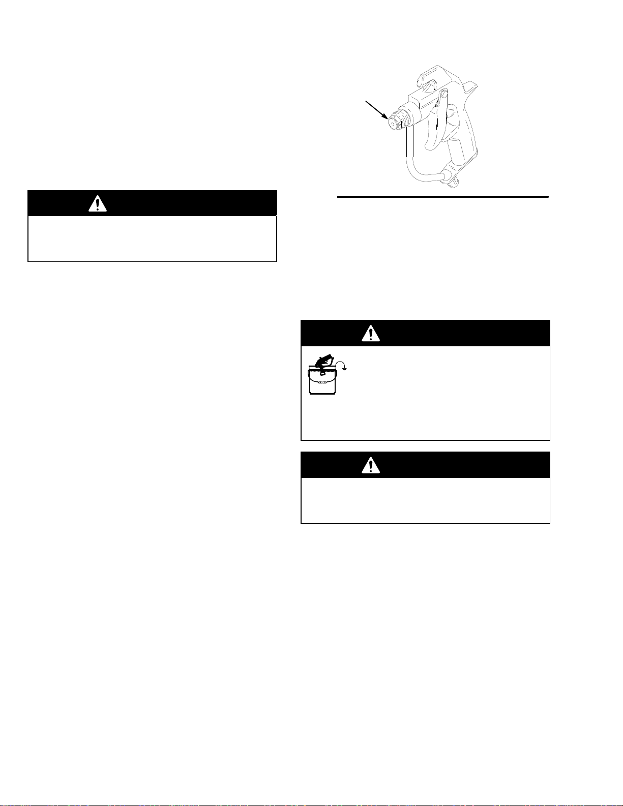
4.
Hold a metal part of the gun firmly to the side of a
grounded metal pail, and trigger the gun to relieve
pressure.
5.
Lock the gun trigger safety
.
6.
Open the drain valve (required in your system),
having a container ready to catch the drainage.
7.
Leave the drain valve open until you are ready to
spray again.
If you suspect that the spray tip or hose is completely
clogged, or that pressure has not been fully relieved
after following the steps above,
very slowly
loosen the
tip guard retaining nut or hose end coupling and relieve
pressure gradually
, then loosen completely
. Now clear
the tip or hose.
System Requirements
WARNING
Be sure your system has a bleed-type master air
valve (pneumatic pumps only) and a pressure drain
valve. These accessories help reduce the risk of
serious bodily injury
, including fluid injection,
splashing in the eyes or on the skin, or injury from
moving parts, if you are adjusting or repairing the
pump or gun.
1.
The bleed-type master air valve
(air-powered
pumps only) relieves air trapped between this
valve and the pump after the air regulator is shut
off. T
rapped air can cause the pump to cycle
unexpectedly.
2.
The pressure drain valve
assists in relieving fluid
pressure in the displacement pump, hose and gun:
triggering the gun to relieve pressure may not be
sufficient.
3.
Strain the fluid you are spraying if it contains
particles which could clog the spray tip.
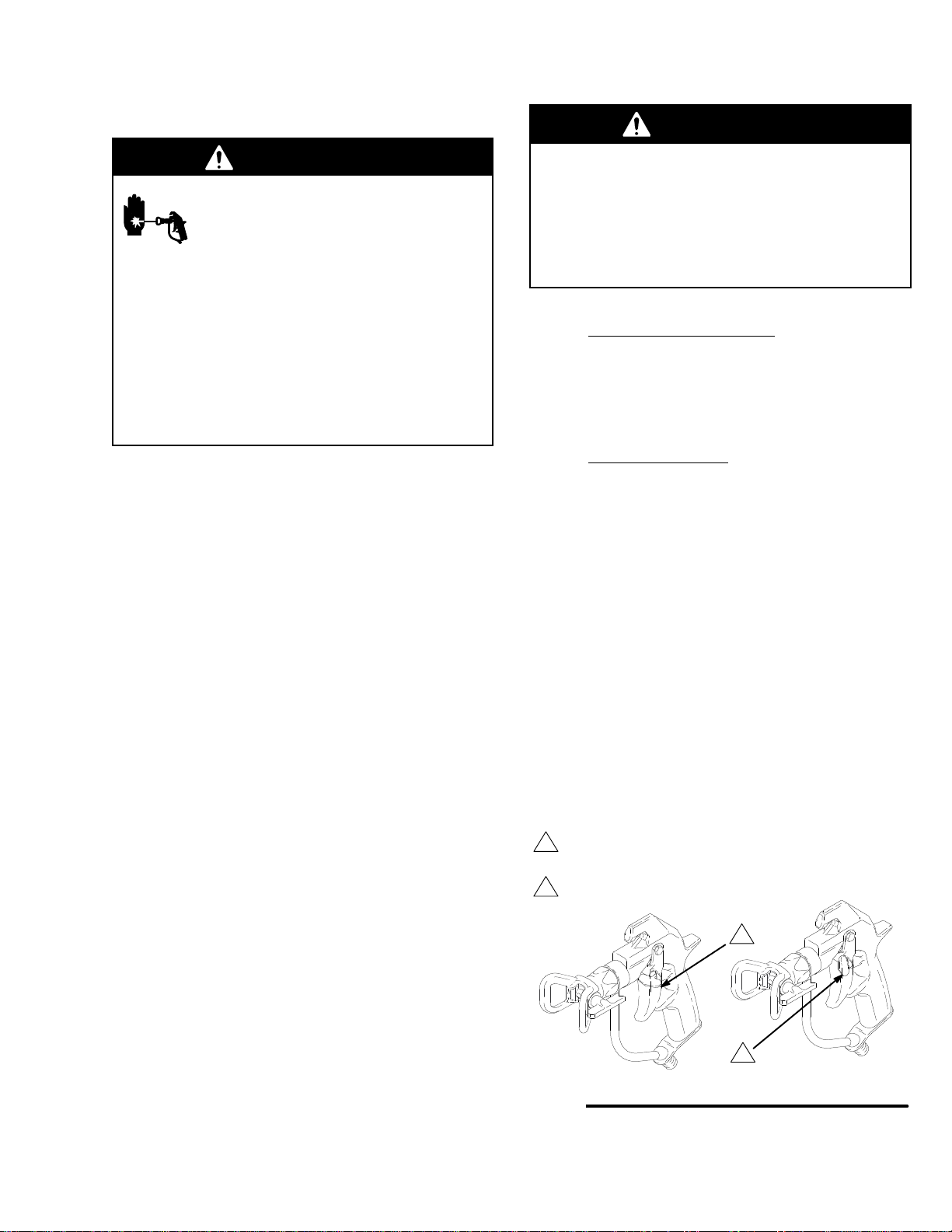
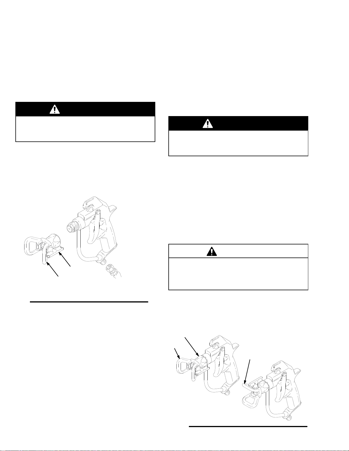
How to Use the Gun Trigger Safety
1. To
lock the gun trigger safety
, turn the latch to a
right angle with the gun body
. See Fig. 1.
2. T
o unlock the gun trigger safety
, push the latch out
and turn it parallel with the gun body
.
Fig. 1
The
trigger safety is shown
in
the locked position.
The
trigger safety is shown
in
the unlocked position.
5