5
Do not install the unit in an extremely humid conditions, as it may result
Do not install the device in areas where poisonous or caustic gases are present.
require insulation depending on the dew point conditions.
Do not use this device as the kitchen’s primary air extraction system. Grease accumulation
In a hot and humid enviroment, the unit must be installed in the highest possible position.
.
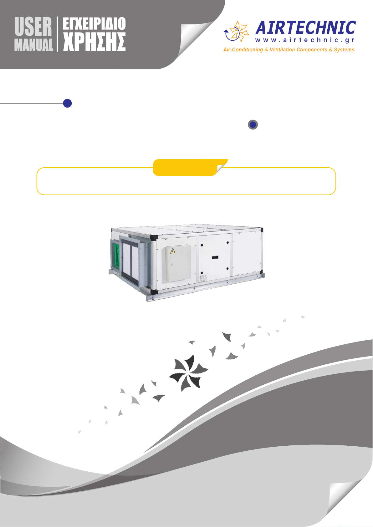
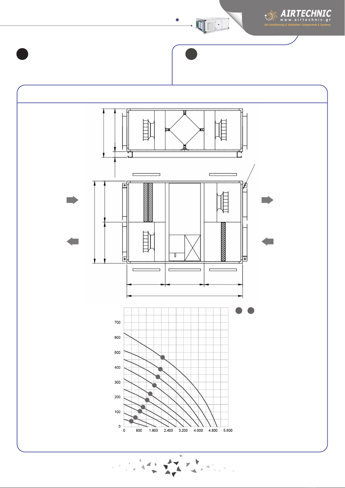
ENERGY BOX TE