manuals.online logo
Brands
  1. Home
  2. •
  3. Brands
  4. •
  5. AirTest
  6. •
  7. Security Sensor
  8. •
  9. AirTest IAQEye TR8910 User manual

AirTest IAQEye TR8910 User manual

This manual suits for next models

6

Popular Security Sensor manuals by other brands

Honeywell Home PROSiXCOCN Installation and setup guide

Honeywell Home

Honeywell Home PROSiXCOCN Installation and setup guide

Duevi SIRPZ-RB-868 Operation

Duevi

Duevi SIRPZ-RB-868 Operation

RKI 65-2483RK Operator's manual

RKI

RKI 65-2483RK Operator's manual

Nortech PD160 Enhanced Series user manual

Nortech

Nortech PD160 Enhanced Series user manual

Omron K8AC-H2 manual

Omron

Omron K8AC-H2 manual

Agilent Technologies G8610 Series Quick reference card

Agilent Technologies

Agilent Technologies G8610 Series Quick reference card

Shinko SE2EA-1-0-0 instruction manual

Shinko

Shinko SE2EA-1-0-0 instruction manual

Det-Tronics X Series instructions

Det-Tronics

Det-Tronics X Series instructions

ACR Electronics COBHAM RCL-300A Product support manual

ACR Electronics

ACR Electronics COBHAM RCL-300A Product support manual

TOOLCRAFT 1712612 operating instructions

TOOLCRAFT

TOOLCRAFT 1712612 operating instructions

Elkron IM600 Installation, programming and functions manual

Elkron

Elkron IM600 Installation, programming and functions manual

Bosch WEU PDO 6 Original instructions

Bosch

Bosch WEU PDO 6 Original instructions

THORLABS PDA10JT user guide

THORLABS

THORLABS PDA10JT user guide

Waeco UV-DETECT operating manual

Waeco

Waeco UV-DETECT operating manual

Intermatic IOS-DSIMF manual

Intermatic

Intermatic IOS-DSIMF manual

Siemens AZL66 Series manual

Siemens

Siemens AZL66 Series manual

BTI Profiline Multi Finder operating instructions

BTI

BTI Profiline Multi Finder operating instructions

Challenger SL01 instruction manual

Challenger

Challenger SL01 instruction manual

manuals.online logo
manuals.online logoBrands
  • About & Mission
  • Contact us
  • Privacy Policy
  • Terms and Conditions

Copyright 2025 Manuals.Online. All Rights Reserved.

1
User Manual: IAQEye (10/24/22)
Quick Overview
The IAQ EYE is a wall mounted, WiFi communicating, air quality transmitter that is designed to monitor
air quality and/or interface to building control equipment. It is available with configuration options for:
• Battery or 24 VAC/VDC: Option of a battery powered (2 AA 3.6V Lithium), or 24VAC/VDC
operation.Battery life of 1 to 1.5 -years at 15-minute sample and send interval.
• E-Ink Display: Option of a bright white, E-ink display or no display versions.
• Visual/Audible Alarm: Ability to set visual and audible alarms for targeted values.
• Add Analog Inputs: Ability to add 3 analog inputs (two 4-20 mA or 0-10V and one 10K2 or 0-5 V
input).
• RTU Interface for CO2 DCV: Ability to add the AirTest RTUiLINK WiFi gateway which connects
the IAQEye™ to a rooftop air handling unit (RTU) with an economizer to provide CO2 based,
demand-controlled ventilation. This connection can either be by a peer-to-peer WiFi connection
or via a local WiFi network.
• Interface to BACnet Control Systems: Ability to use the BB3-7301-AT Babel Buster WiFi-to-
BACnet gateway to connect the transmitter to a BACnet control system. One gateway supports
up to 100 Transmitters. Measurement data appears as BACnet objects in the Babel Buster
interface.
• Cloud Data Monitoring: A cloud portal is available to allow for monitoring, profiling and storage
of data measured. This option is a factory setting and must be ordered at time of sale.
• IAQEye Reporter: Connect to the IAQEye™ with a phone using the QR code on the bottom
label. A summary of the last week of data is visible on the phone. Feature enabled in late of
2022 if the device is connected to the internet.
2
Model Numbers
Functionality
3
IAQEye™ Interface Options
1. LEED Mode: Stand Alone Monitoring and Alarm
The IAQEye™ in battery or powered mode can display the values of
Temperature, Humidity, Dew Point and Carbon Dioxide. It is also possible to
program the IAQ Eye to illuminate LED lights (Green, Yellow, Red), and sound
an audible alert if levels of any measured parameter exceed a user defined
level. The status bar on the display can also show the elevated measure
parameters with an exclamation mark (CO2!).
2. Integration Into 3rd Party IP Based Monitoring Systems
The IAQEye™ communicates over WiFi and the internet using a UDP protocol.
This information can be sent to any internet or network connected device to
capable of translating the UDP packets . The UDP communication protocol can
be downloaded at this link: https://www.AirTest.com/man/IAQEyeUDP.com .
3. RTUiLINK™ :Adds CO2 DCV To Rooftop HVAC Systems
The RTUiLink (TR4201) is a WiFi receiver that is placed in a RTU to provide a
CO2 DCV signal to the economizer from the IAQEye™ mounted in the space.
Communication can be peer-to-peer between devices or part of a larger WiFi
network that may already be in place. Designed for RTUs controlled by
thermostats where the CO2 signal is driven by a 0-10 or 2-10 VDC input into a
fresh air economizer control.
4. CLOUDiLINK™: Internet Based Cloud Monitoring and Alarm
This is a feature that can provide a secure, cloud-based dashboard to show
measurement values, short- and long-term trends. The application can also
send email and text alerts and is designed to support multiple dispersed
geographic locations and multiple spaces at a particular location. This service
requires a secure factory installed certificate is installed the IAQEye™ at time of
manufacture.
5. Babel Buster Gateway: BACnet IP/TC IP Interface
The Babel Buster is a WiFi gateway that allows up to 100 IAQEye™ devices to
connect to a BACnet IP or TCP IP building control network with each
measurement parameter read as a BACnet object. The gateway is attached to
a local WiFi router near a BACnet network access point. A built-in webserver in
the Babel Buster allows configuration to the building control system. This
gateway will only work with products utilizing the IAQEye™ UDP
Communication protocol.
4
Connecting and Configuring The IAQEye™
The IAQEye™ has a built-in web server that allows local access and adjustment of the transmitter
settings. To access the server, you must be withing 30 feet of the IAQEye with a WiFi enabled
smartphone, tablet or computer. This section describes how to set up the units and adjust its
operational settings. You may want to consider doing the initial setup on the unit at a bench before
traveling to the installation site.
1. Password Labels: The IAQEye™ is provided with two sets of labels that contain the unique 12-
Character MAC address for the transmitter and a password that enables log on access to the
IAQEye™. You can keep one version for your records and attach one to the enclosure. We
recommend that the label be placed on the back of the front cover at the bottom.
2. Open The Enclosure: The IAQEye™ enclosure must be
opened to fasten the base to a wall, to attach the password
label, to activate the device batteries or provide 24VAC/VDC
power wiring. Grip the case at the mid-way point and squeeze
inward. At the same time hook the finger of your other hand into
the wiring port on the back of the case and pull. When the device
is screwed to the wall, squeeze the sides of the case and pull
away from the wall.
3. Enabling power to the IAQEye™:
o For battery powered units, there is an on-switch on
the inside cover in the lower right corner of the circuit
board. If you are providing low voltage power to the
device, turn the battery switch off. If the device will
not be operating for a period of time, say after an
initial setup, turn the batteries off.
o For low voltage wiring (24VAC/DC) use 18-to-22-
gauge wire. Wires can be drawn through the rear
wiring port. The terminal blocks incorporate a lever
wire clamp that when pressed allows the
wire to be inserted into the side of the
terminal block. When the lever is
released, the wire is clamped in place.
The power wiring terminals are in the
red highlighted box labeled C (Common)
and R (Rail, DC +).
o A local CO2 0-10 VDC output is
available on the terminals on the upper
right labeled Ground and VOUT.All setting adjustments for the IAQEye™ using the WiFi
interface will affect this output. I
o When wiring or battery activation of the backplate
is complete, place for fit and press the front cover
into the back plate.
5
4. Accessing the IAQEye™ On-Board Webserver for Product Configuration.
o The IAQEye™ must be powered to interface to the webserver. This means the device must
be hard-wired or battery-operated and in the awake state. Awake means the device is in a
mode to connect via WiFi and/or to make a measurement.
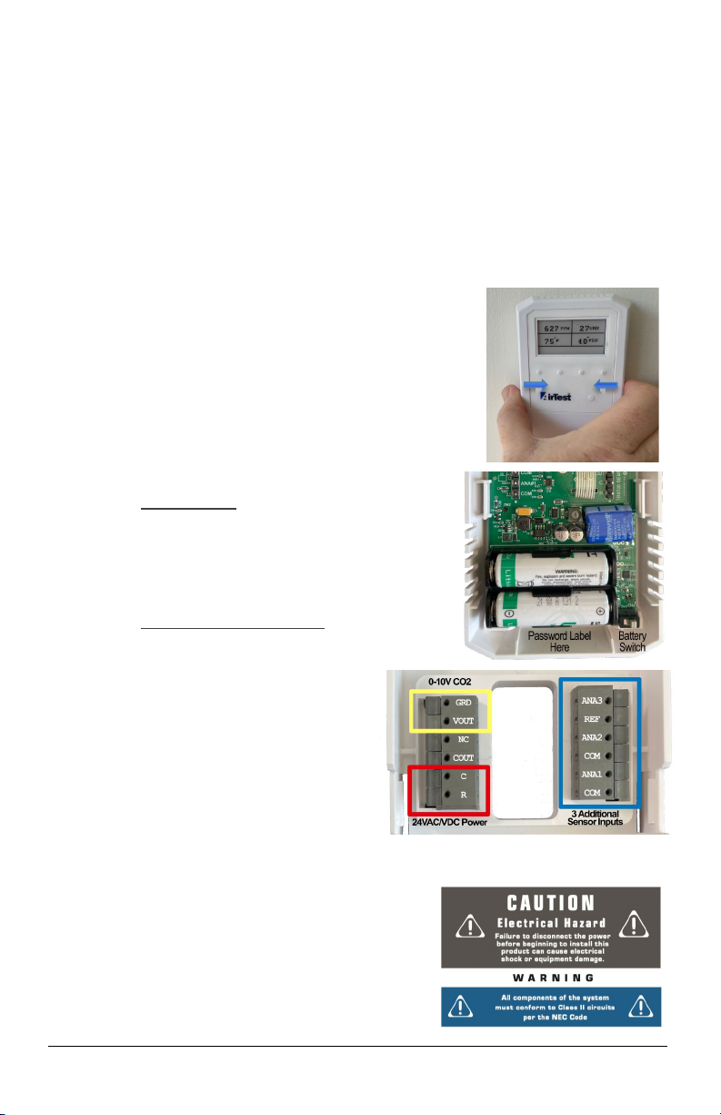
o If line-powered, the IAQEye™ is always in the
awake state. To wake up the device for battery
press and hold the raised button on the front cover
to the right of the AirTest logo for 10 seconds. After
10 seconds, the device will beep, two LEDs will
illuminate on the front cover. If there is a display, it
will go through a 20 second initiation process.
Once awake a green led will be illuminated on the
right side of the front cover indicating it is WiFi
accessible for 15 minutes.
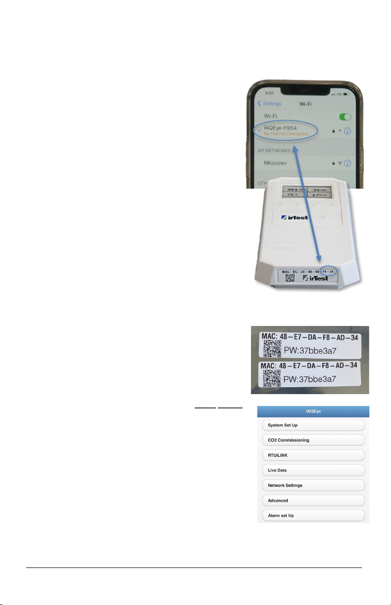
o Once the IAQEye™ is awake, it’s time to connect to
its webserver. On your phone, tablet or computer go to
find local WiFi networks (SSIDs). Look for the network
that identified as “IAQEye-XXXX” (where XXXX is last
four characters of the MAC address of the unit you
want to configure). The MAC address is on the bottom
of the device.
o Select the WiFi network of the unit you want to adjust.
You may get an alert that says “no internet connection”.
That is because you are connecting to the device, not
the internet. This message is not a concern.The
connection is made at 2.4 GHz.
o Go to your web browser and input the address 192.168.10.1 into the browser which will
provide access to the IAQEye™ internal web server
and allow for adjustment of the transmitter settings.
o Next you will be asked for a password. Input the
password. Your WiFi connecting device should
remember this password for future connection, Your
IAQEye™ unit unique password is provided on two
labels provided with the unit. We suggest one of these
password labels should be affixed to the inside bottom
of the product enclosure as shown in the photo on the
previous page. The second label is used for your
records.
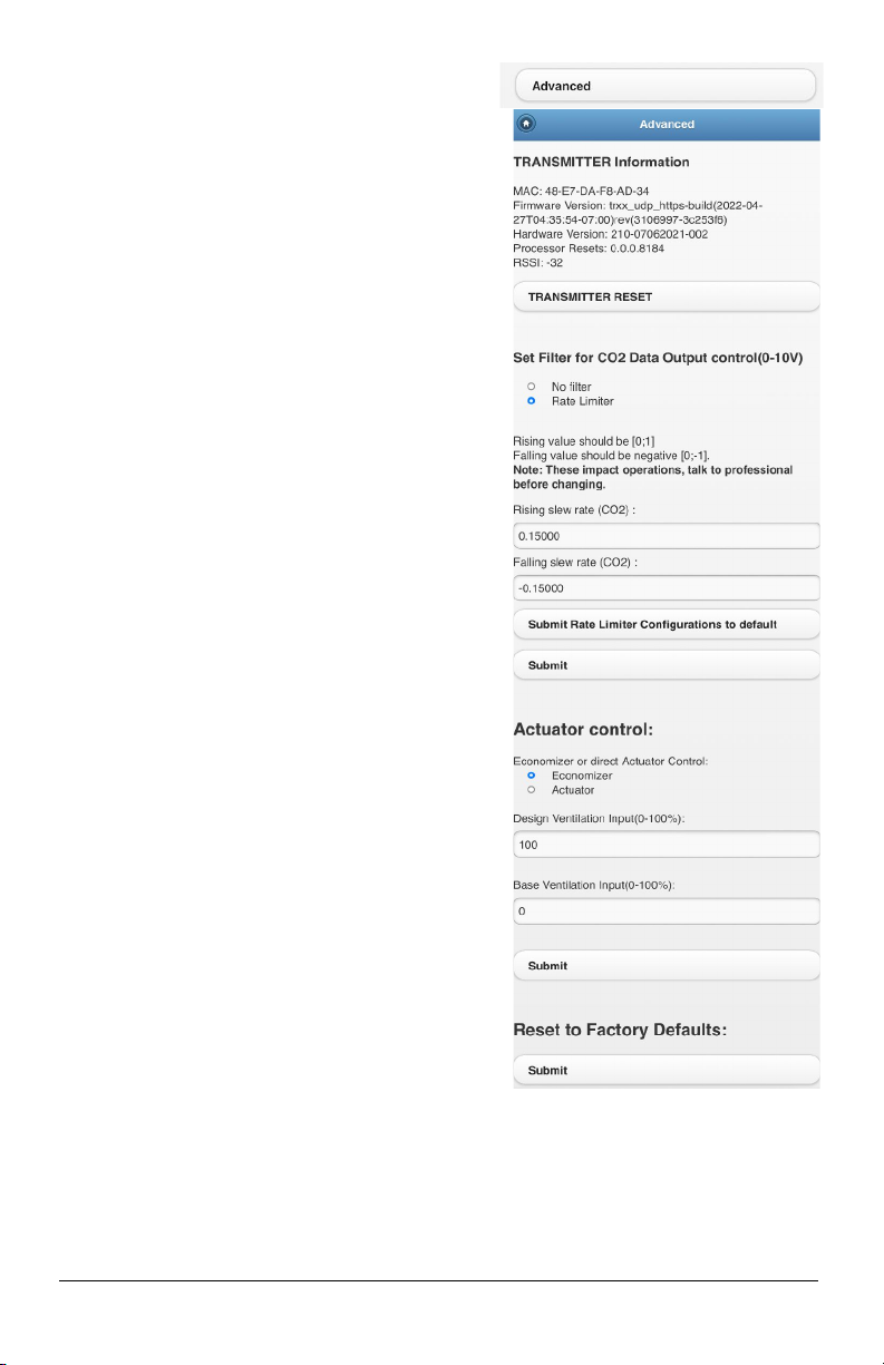
o The IAQEye™ menu should now appear on your
screen.( (See photo to the right).
o Note: The WiFi interface will disconnect after a period of
15 minutes. To re-activate the interface, hold the button
to the right of the Airtest Logo for 10 seconds or until the
LEDs on the front cover blink along with an audible
sound. You will have to reconnect to the sensor SSID to
continue adjustments to the interface.
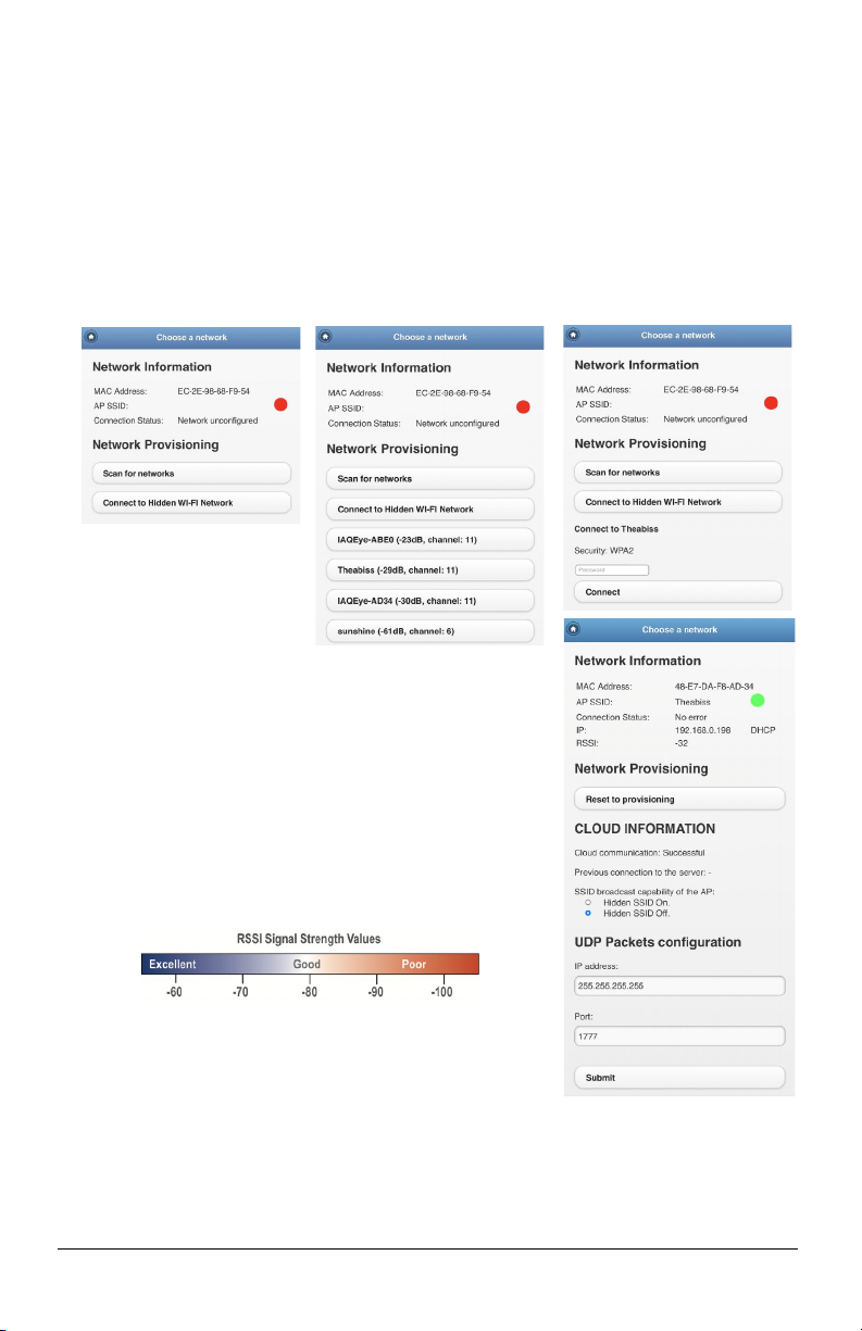
o Now select the Network Settings to go through the process of connecting to a local network.
5. Network Settings Section
6
Shown below on this page are four sequential captures of the Network Selection process for the
IAQEye™. To set up the network you will have to know the SSID and password of the network you will
be joining. Note: the IAQEye™ is designed to connect only to 2.4 gHz networks.
• The selection process allows you to connect to a visible network, or a hidden network (Graphic 1)
• If you select a hidden network, you will be prompted to input the SSID and password for the
network and press the connect button.
• If you select scan for networks a list of all visible networks available will be provided. Select the
appropriate network and input the password and press the connect button.
• If you are using a RTUiLINK™ with the IAQEye™ you have two connection options. You can
connect directly through the SSID of the RTUiLINK™, or communicate to it through the local
network. Note the RTUiLINK™ must be set up prior to connecting the IAQEye™.
• If you connect directly to
the RTUiLINK™
information will only be
shared between connected
devices and the units will
not communicate to a local
network or the internet. An internet connected network is
required to provide firmware updates, to establish a
CLOUDiLINK™ connection. A local network connection is
required to utilize the Babel Buster gateway to connect to
BACnet control systems.
• The final graphic on this page shows an example of a good
connection.
o There is a green circle next to the SSID name
o Connection status says no error
o An IP address is assigned to the unit
o The RSSI signal indicates the strength of the wireless
connection to whatever the IAQEye™ is connected to.
UDP Packet Configuration
This configuration is only used in conjunction with the Babel Buster
Gateway intended to communicate to BACnet IP and MS-TP
networks. The default IP address and Port as shown in the graphic sends the UDP Data Packet from
the IAQEye™ over the entire network. Data can also be sent to a specific receiving address IP and
port. If the UDP is not being used, it can be directed to a unused address and port.
7
6. IAQEye™ System Setup
Temperature Units:
• Select temperature output in Metric (Celcius) or IP
(Fahrenheit) values.
• Device label is a custom descriptor for the location.
• Press Submit to make changes.
Offsets (Temp and % RH)
• Change these only if you are sure there is a need offset to
these values. Press Submit to make changes.
Sample Duration/Sampling Interval (in Minutes)
This is the sampling Interval at which the IAQEye™ takes a
measurement and updates the display.
o If operated on line power this should be set at 1 minute or more.
o If operated on battery power, best battery life (1.0 to 1.5 years)
occurs at an interval of 15-20 minutes setting.Battery life will
increase the higher the value.
Set API ET Interval
The API Function is used for firmware updates and cloud
monitoring. The API ET count is the broadcast interval at which
this data is set as a function of the sample duration. A value of 2
would mean there would be a broadcast every 2nd measurement.
Only the most current measurement is broadcasted. Default is 1.
The API function is the method of communication to the Amazon
Cloud and AirTest’s CLOUDiLINK™
Set UDP Interval
UDP is the information package sent by the IAQEye™ over the
WiFi network and the Internet. This is used by the Babel Buster
to Translate measured data into BACnet objects. Like the API
Interval above the UDP interval is a function of sample duration.
Setup Analog Inputs
The IAQEye has the ability to take 3 analog inputs (ANA1, ANA2
and ANA3) from other transmitter devices and broadcast it as part
of the units UDP communication protocol. Wiring terminals are
shown in the wiring section. Note: to use this analog input function
the IAQEye™ must be 24VAC/VDC powered.
If an analog input is used it should be enabled or turned off if not in
use. The radio buttons show the type of input allowed. Changing
the radio buttons will not change the input permitted which are:
ANA#1=0-10V, ANA#2 =4-20 mA and ANA#3 =0-5 Volts. If
different inputs are required from that shown it must be configured
when ordered.
The notes section allows up to 40 characters to describe what is
being measured and the measurement range. Analog values
measured will be broadcast as part of the UDP transmission of the
IAQEye™
8
7. CO2 Commissioning
This section facilitates the adjustment of a number of
factors that affect the behavior of the IAQEye™. It is
important to note that CO2 adjustments in this section
affect the CO2 output on the IAQEye™
Sets the ppm Low/High range to control the damper
position for demand-controlled ventilation. Note any of
the IAQEye settings relate to the CO2 voltage output that
is on-board the IAQEye™. If using the RTUiLINK™,
Settings must be adjusted through the RTUiLINKTM.
DCV Status is an indicator flag that can be read by the
cloud to indicate if DCV is being utilized with this device.
• Typically, the low setting would be 0 ppm.
• Upper range should be set at 2000 ppm for
interface to most HVAC equipment. The CO2
Sensor does not measure over 2,000 ppm. Press
Submit to save settings.
This section establishes the CO2 Levels that LED
Indicators on the front cover of the IAQEye™ will
illuminate (Red/Amber/Green indicators).
• Recommend Green LED Limit 1000 ppm CO2.
• Recommended Red LED Level 1500 ppm CO2.
Select the VDC CO2 output range desired on the
IAQEye™ for a 0-10 or 2-10 VDC Range. Default is VDC
0-10.
Press Submit to save settings.
The Damper Test can be used as part of the
commissioning process to test to see if the CO2 output
from the IAQEye™ is actually modulating the damper.
Input a value for the test damper position. A 50 % value
would be a 5 VDC signal if set to 0-10V above. The user
can then check to see if the damper is at the 50%
position. Test will auto shut off after 10 minutes.
Note: These adjustments only affect the IAQEye™ VDC
output. If you are using RTUiLINK to control an air
handler the CO2 adjustments have to be made through
the RTUiLINK adjustment interface.
The IAQEye utilizes a dual beam, pressure corrected
CO2 self-calibration process so adjustment of CO2
calibration is not recommended. This adjustment should
only be used if the installer is certain an adjustment is necessary.
9
8. RTUiLINK™
The RTUiLINK™ is an accessory for the IAQEye™ that
allows the CO2 signal from IAQEye in the space to be
broadcast to a receiver inside a nearby Rooftop Air
Handling Unit (RTU). The RTUiLINK™ provides a 0-
10VDC signal to a CO2 capable economizer in the RTU.
The RTUiLINK has a similar WiFi interface to the IAQEye™
that needs to be also configured.
The upper graphic to the right shows what the interface
looks like where it is not connected to an RTUiLINK™. A
later section of this manual will explain how to have a
IAQEye™ connect to a specific RTUiLINK™ by using the
RTUiLINK™ WiFi interface.
The second graphic on the right, shows the heartbeat of the
RTUiLINK, indicating that the IAQEye is connected to the
RTUiLink™.
9. Live Data
This page provides the current readings for all measured
variables of the IAQEye™. It is designed to update while
you are viewing at the interval set in the System Setup
menu item.
10
10. Advanced Settings
This section allows for advanced adjustment and
diagnostics for the IAQEye™. Most users should refrain
form adjusting any of the parameters on this page without
clearly understanding the impact. If you accidently change
a value, there is an option to reset to Factory Defaults at
the bottom of this screen.
Transmitter Information
This section provides a number of details regarding the
IAQEye™ identity, hardware and software versions. This
information may be required if troubleshooting is
necessary with an AirTest Engineer.
Set Filter for CO2 Data Output
These values relate to the response characteristics of the
CO2 signal. Please contact AirTest if you feel you need to
adjust these parameters.
Actuator Control
In some cases, a user may want to directly drive an
actuator or VFD rather than input the CO2 signal into a
Economizer. Click on the radio button for Actuator, and
set the values in the boxes for the maximum setting
(Design Ventilation) and the minimum setting (Base
Ventilation) . If values are changed, press Submit to
finalize the change.
Not any adjustments to the CO2 parameters on the
IAQEye™ (with the exception of the Filter data above),
only affect the output of the CO2 analog output on board.
It does not affect CO2 parameters in remote application
like the RTUiLINK™, ICLOUDiLINK and Babel Buster.