PHS1500/4000 User’s Guide
1029.00.902 4
1.2 Heater Limited Life Warranty
Air-Vac Engineering Company warrants the heaters for a period of ninety (90) days from date of shipment.
Air-Vac agrees to repair or replace any or all such equipment that may prove to be defective within the warranty period, with-
out expense, excluding shipping to the owner. This warranty shall not apply to any products that have been repaired or altered
except by Air-Vac Engineering. Services under warranty shall not affect an extension of the warranty period, nor will a new
warranty period be granted for the parts, which were replaced/repaired. The title of the replaced parts will automatically pass
to Air-Vac.
Air-Vac reserves the right to reject replacement under this warranty where, in the sole opinion of Air-Vac, the defect is due to
obvious misuse and/or improper maintenance of the module or any part thereof.
Heating element life is affected by several factors, temperature, airflow, condition of incoming air (water
and oil contamination) and overall process cycle. These products are considered a “consumable” item.
The length of useful service will vary based on the conditions under which they are run. Higher tempera-
tures and/or lower flows will cause shortened life.
The express and/or implied warranty of Air-Vac is limited to the replacement and/or repair of any item defective in material
and/or workmanship. Other damages, if any, direct or consequential are expressly excluded from this warranty.
Air-Vac shall be liable under this warranty only if 1) Air-Vac receives notice during the warranty period; 2) The products are
operated in accordance with the supplied documentation; and 3) Such products are, to Air-Vac’s satisfaction, determined to be
defective.
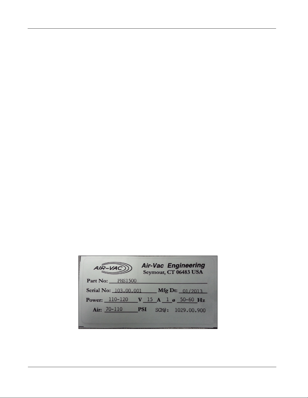
When contacting Air-Vac for warranty inquiries, please provide the Order Number that the parts were shipped, Model and Serial
Number of the product and the Reason for Warranty. Products cannot be returned to Air-Vac without authorization – please call
for an RMA #.
1.3 Safety
The PHS Preheater was designed with safety of the operator in mind. The operation and maintenance
of the system must be performed cautiously due to the nature of the hot surfaces, flux and molten solder
involved in the assembly and rework of printed circuit cards.
NOTE:
WHEN OPERATING THE AIR-VAC PHS PREHEATER, FOLLOW ALL LOCAL CODES FOR SAFE OP-
ERATION OF THE MACHINE. DISPOSAL OF MATERIALS USED IN THE PROCESSING OF PRINTED
CIRCUIT BOARDS MUST BE DONE IN COMPLIANCE WITH EACH MANUFACTURERS RECOMMENDA-
TION IN ACCORDANCE WITH LOCAL CODES.
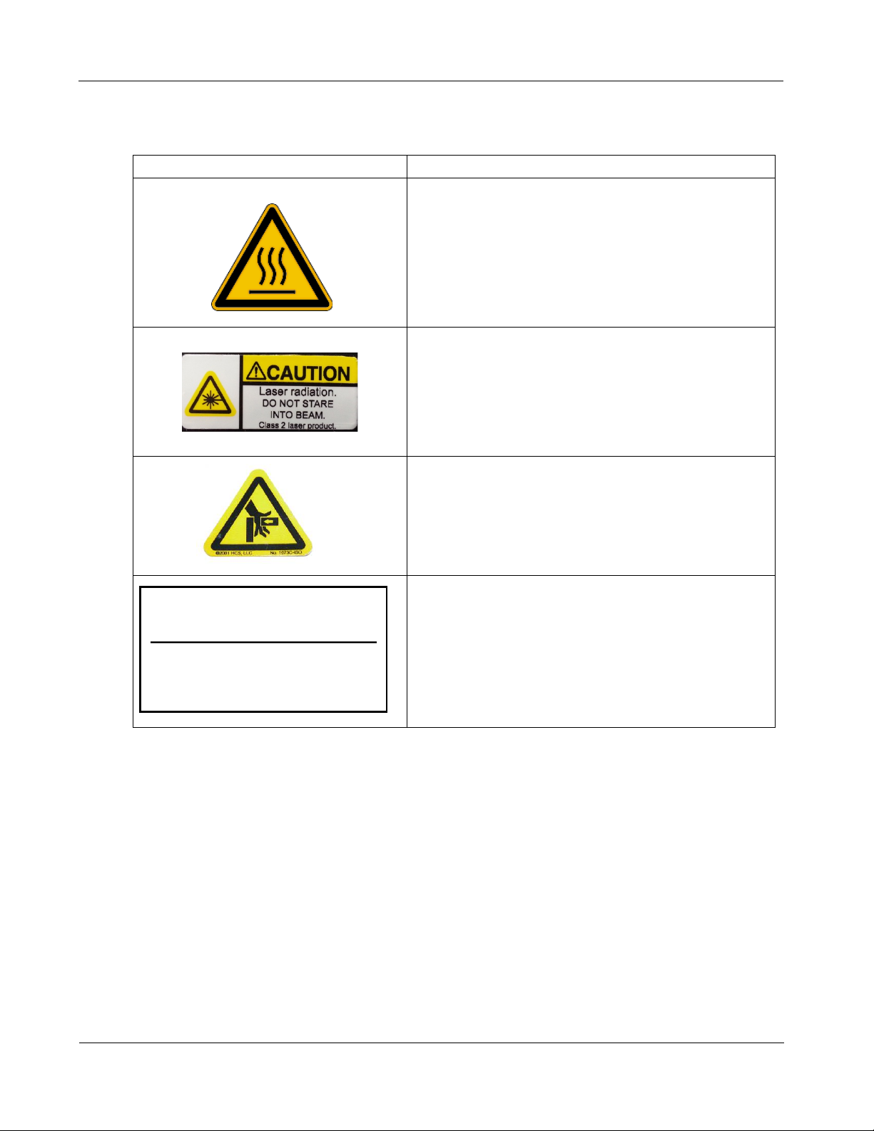
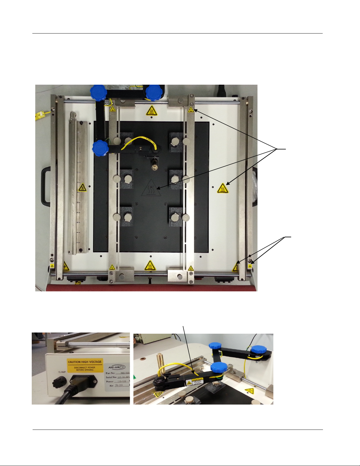
Other safety items include:
• Operator safety warning labels and markings are employed.
1.3.1 Safety Instructions & Recommendations
Machines and tools of Air-Vac can only be used with maximum efficiency and safety by properly trained
personnel.