Minimum Clearances
Heater to Floor: heat er may be mount ed direct ly on finished
foor or, if desired, above floor (such as above t he baseboard).
Up t o 3/ 4 inch (19 mm) of carpet ing may be inst alled up t o and
around heat er as long as it does not obst ruct t he air flow.
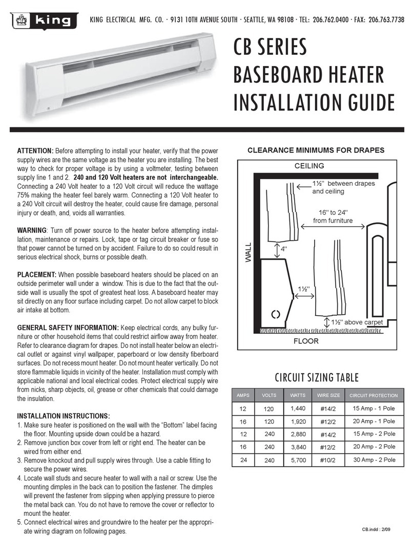
Heater to Drapery: do not inst all heat er where curt ains or
drapery will cont act t he heat er. See Figure 2 for required mini-
mum clearances.
Furniture: maint ain at least 6 inches (152 mm) space bet ween
f urnit ure and heat er t o allow f or proper air flow.
UNPACKING HEATER
Check heat er t o make sure it has not been damaged in
shipping. Do not inst all or at t empt t o operat e t he heat er if
damaged. Ret urn t o place of purchase or fileclaimwit h
freight carrier.
INSTALLATION INSTRUCTIONS
1. Serious inj ury or deat h coul d result f rom elect ric shock.
Make sure elect rical power suppl y circuit coming t o heat er
is disconnect ed at main disconnect or service panel bef ore
inst alling t his heat er.
2. Wiring procedures and connect ions must be in accordance
wit h t he Nat ional Elect rical Code (NEC) and local codes.
Refer t o Wiring Diagrams Figure 5. Make sure all elect rical
connect ions are t ight t o prevent possible overheat ing. Use
Copper Supply Wire Only.
3. Verif y t he elect rical power supply volt age mat ches t he
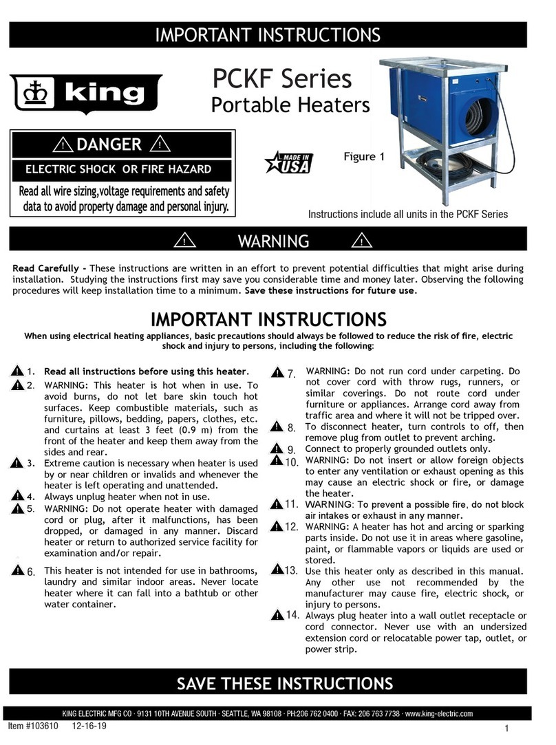
volt age rat ing as print ed on t he heat er nameplat e – see Fig-
ure 1.
TO REDUCE THE RISK OF FIRE AND ELECTRIC SHOCK
OR INJURY TO PERSONS, OBSERVE THE FOLLOWING:
CAUTION - Never connect a heater to a voltage
greater than the nameplate voltage as this will
damage the heater and could cause a fire.
4. Do not inst al l t he heat er against combust ible low-den-
sit y cellulose fiberboard surfaces, against or below vinyl wall
coverings, or below any mat erial s t hat may be damaged by
heat such as vinyl or pl ast ic bl inds, curt ains, et c.
5. Do not inst al l heat er below an el ect rical convenience re-
cept acle (out let ).
6. CAUTION – Heat er Operat es at High Temperat ures. Keep
Elect rical Cords (including t elephone and comput er cabl es),
Drapes, and Ot her Furnishi ngs Away From Heat er. For ef fi-
cient and saf e operat ion, we recommend maint aining a mini-
mum of 6 inches (152 mm) cl earance above and in f ront of
t he heat er at al l t imes. See Figure 2 f or minimum clearance
requirement s f or drapery.
7. To reduce t he risk of fire, do not st ore or use gasoline
or ot her flammable vapors or liquids in t he vicinit y of t he
heat er.
8. Do not inst all heat er upside down or in any posit ion ot her
t han as shown in t his manual. Caut ion label wit h word “ TOP”
must be at t he t op when heat er is inst alled.
9. Do not recess heat er in wall or inst al l heat er inside any
t ype enclosure as t his will cause heat er t o overheat and
could creat e a hazard.
10. When mount ing heat er, (see Figure 4), make sure screws
do not damage crossover wiring or t he saf et y limit in t he
heat er.
11. Do not remove or bypass t he saf et y limit cont rol as t his
could allow heat er t o become a fire hazard – see Figure 4.
12. When using Transf ormer Relay Accessory, supply wiring
provided in compart ment where t his accessory is inst all ed,
must be rat ed 90 ° C minimum.
Important Note: Certain fabrics and materials discolor or may
become damaged by heat. Therefore, avoid installing heater
against vinyl wall coverings or below plastic or vinyl items such
as blinds or vinyl drapes since these items may become
damaged by the heated air flowing from the heater.
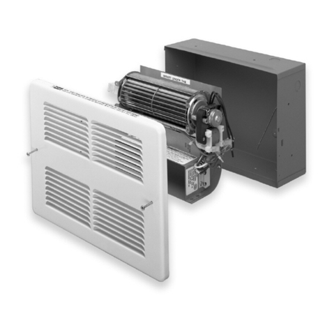
1. Remove wiring compart ment cover at end of heat er where
power suppl y cable is t o ent er (Figure 3). Det ermine desired
mount ing locat ion, posit ion heat er t o wall and mark wall
(or floor) at l ocat ion where power supply is t o ent er heat er.
2. The air inlet of the heater cannot be obstructed by the
finished floor materials such as carpet, tile or hardwood. The
installer, must make allowance for the finished floor materials
when installing the heater during rough-in construction on a
subfloor. For example if thickness of the padding and carpet
to be installed is 3/4", then the heater must be mounted 3/4"
above the subfloor.
Figure 3
Wiring compartment
cover Front Cover
Screw
NOTE: For most efficient operation locate heaters along out-
side wall under windows. Posit ion heater so it can be secured
to wall stud. Power cable must enter heater through built
in cable clamp or one of the knockouts provided in wiring
compartment .
Figure 2:
Clearance f or
Drapery and Finished
Floor
2. Drill hole in wall (or floor) at desired l ocat ion f or power sup-
ply ent ry. Inst all power supply wiring t o heat er and t hermost at
locat ion as det ermined by t hermost at opt ion select ed. Allow
approximat el y 10 t o 12 in (254mm t o 305mm) of wire at heat er
f or connect ions.
3. If any accessories are t o be used wit h t his heat er, ref er t o
inst allat ion inst ruct ions provided wit h t he accessory f or proper
inst allat ion and wiring. Visit www. king-elect ric.com for inst ruc-
t ions on some common accessories.
4. Posit ion heat er at desired locat ion and at t ach t o wall using
good screws or appropriat e hardware. Locat e st uds and drive
screws int o st uds where possible. For heat ers up t o 6 f eet (1.8
m) in lengt h, one screw at each end is adequat e. For longer
unit s, an addit ional screw in cent er is required. Tight en screws
and t hen loosen screws at least ¼ t urn t o allow heat er t o ex-
pand and cont ract during use. If unit is mount ed above floor,
t wo addit ional mount ing hol es are provided at each end below
t he heat ing element (see Figure 4). Inst all an addit ional screw
at each end f or st abilit y making sure t o loosen each screw at
least ¼ t urn.
5. Connect t he supply cable grounding wire t o t he green wire
pigt ail in wiring compart ment .
WARNING
