1 General 4
1.1 About these instructions 4
1.2 Safety information 4
2 Power connection and wiring 5
2.1 Core module and connection options 5
2.1.1 Board view - core module 5
2.1.2 Mains connection 7
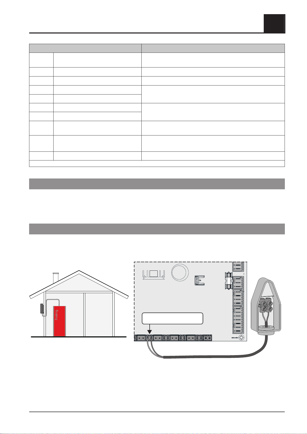
2.1.3 Connecting the outside temperature
sensor
7
2.1.4 FRA room temperature sensor 8
2.1.5 Boiler enable contact 8
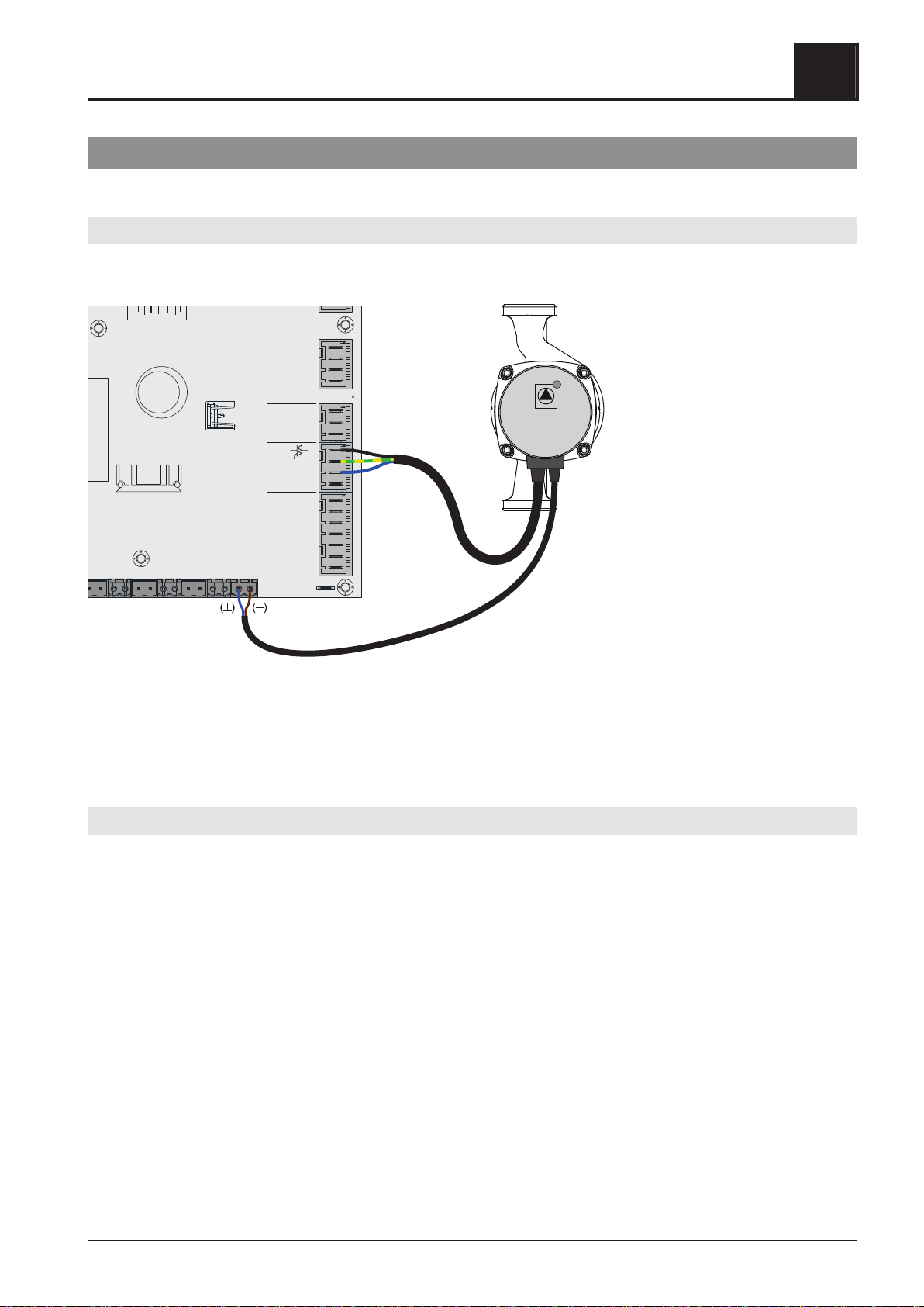
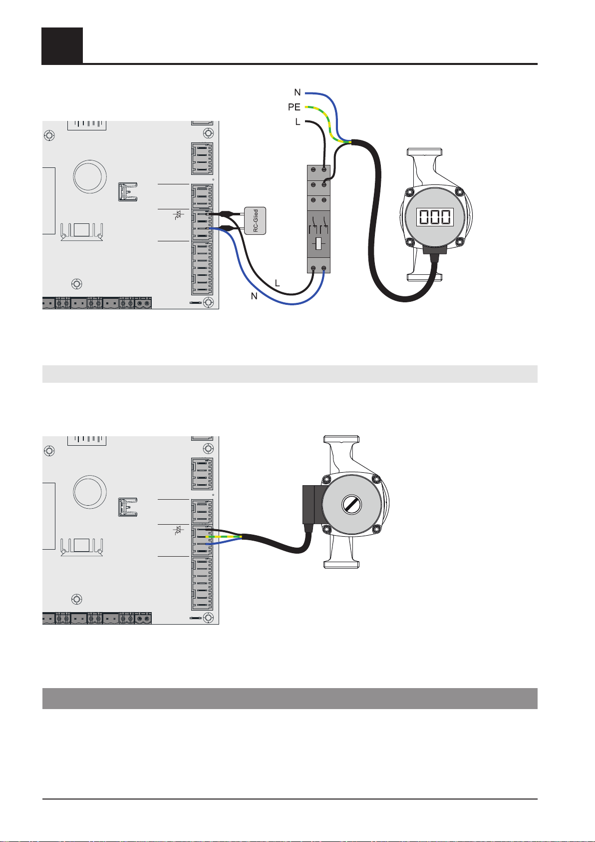
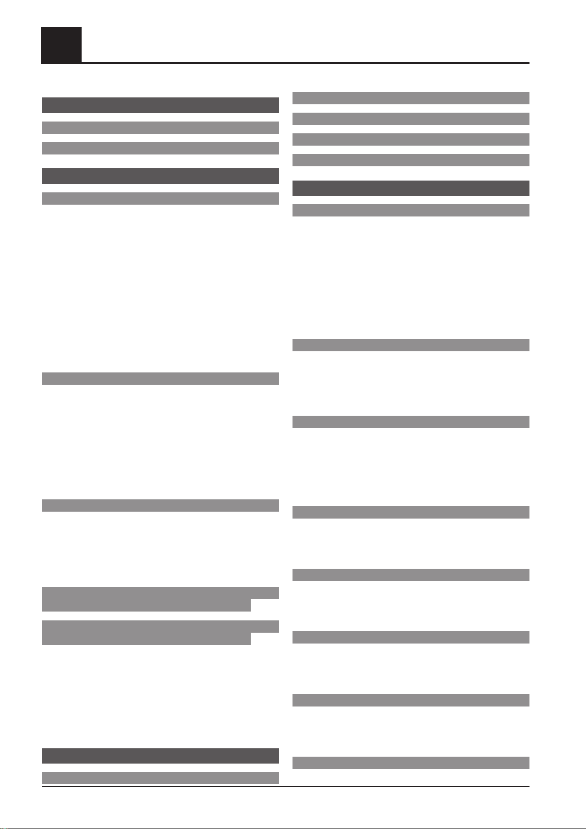
2.1.6 Connecting a circulating pump to the core
module
9
2.1.7 Connecting an isolating valve to the core
module
10
2.1.8 Heating circuit pump 0 / burner relay 12
2.1.9 Operating signal 12
2.2 Expansion modules 13
2.2.1 Heating circuit module 13
2.2.2 Hydraulic module 14
Connecting a circulating pump to the hydraulic
module
15
Connecting an isolating valve to the hydraulic
module
19
2.2.3 Pellet module 20
2.2.4 Pellet module expansion 22
Automatic room air flap
23
2.3 BUS connection 24
2.3.1 Connecting the bus cable 25
2.3.2 Setting end jumpers 25
2.3.3 Setting the module address 26
2.3.4 Potential equalisation / potential
separation
27
2.4 Connection information according to
pump types
28
2.5 Connection options with standard
delivery
29
2.5.1 System 0 (DHW tank / one heating
circuit)
29
2.5.2 System 0 (two heating circuits) 30
2.5.3 System 1 (layered tank / two heating
circuits)
31
2.5.4 System 1 (hygienic layered tank / two
heating circuits)
32
3 Initial startup 33
3.1 Switching user level 33
3.2 Default configuration 33
3.3 Setting the system selection 34
3.4 Before heating up for the first time 36
3.5 Starting the system on initial startup 36
4 Parameters overview 37
4.1 Heating 37
4.1.1 Heating - Status 37
4.1.2 Heating – Temperatures 38
4.1.3 Heating - Times 39
4.1.4 Heating - Service 39
4.1.5 Heating - Heating up program 40
Heating up programs
41
Configure program 8
41
Heating circuits used
41
4.1.6 Heating - General settings 42
4.2 Water 43
4.2.1 Water - Status 43
4.2.2 Water - Temperatures 43
4.2.3 Water - Times 44
4.2.4 Water - Service 44
4.3 Solar 46
4.3.1 Solar - Status 46
4.3.2 Solar - Temperatures 47
4.3.3 Solar - Times 48
4.3.4 Solar - Service 48
4.3.5 Solar - Heat meter 50
4.4 Buffer tank 51
4.4.1 Buffer tank - Status 51
4.4.2 Buffer tank - Temperatures 52
4.4.3 Buffer tank - Service 52
4.5 Boiler 2 53
4.5.1 Boiler 2 - Status 53
4.5.2 Boiler 2 - Temperatures 53
4.5.3 Boiler 2 - Service 54
4.6 Feed system 55
4.6.1 Feed system - Times 55
4.6.2 Feed system - Service 55
4.6.3 Feed system - Consumption 56
4.7 Network pump 57
4.7.1 Network pump - Status 57
4.7.2 Network pump - Temperatures 57
4.7.3 Network pump - Service 58
4.8 Difference regulator 59
4.8.1 Difference regulator - Status 59
Table of contents
2 Froling GesmbH | A-4710 Grieskirchen, Industriestraße 12 | www.froeling.com