Airxcel VELARIUM User manual

POWER AWNINGPOWER AWNING
Installation ManualInstallation Manual
2023 AIRXCEL, INC. All rights reserved. All information presented herein is subject to change without notice.

Service Log
©Velarium, an Airxcel Brand® Power Awning Installation Guide
230913
p. 2
Caution Notes
Contents
Caution Notes.................................................2
Introduction ....................................................3
Awning Installation.........................................4
Securing the Fabric........................................5
Seal Wall Penetrations...................................5
Wiring..............................................................6
Warranty .........................................................7
Caution Notes
As you read this information, take particular note of the NOTICE,
CAUTION, WARNING, and DANGER symbols when they appear. This
information is important for safe and efcient use of the Velarium
Power Awning.
NOTICE
signals a situation where potential damage to the Velarium
Power Awning could occur.
CAUTION signals a situation where potential harm or risk of minor or
moderate injury could occur if you do not follow instructions.
WARNING signals a hazardous situation where potential harm, risk
of serious injury, or death could result if instructions are not followed.
DANGER signals a situation where immediate risk of serious injury or
death will result if instructions are not followed.
NOTE: This manual will also use notes sections similar to
this one to draw attention to features and practices which
must be observed.

Service Log
©Velarium, an Airxcel Brand® Power Awning Installation Guide
230913
p. 3
System Information
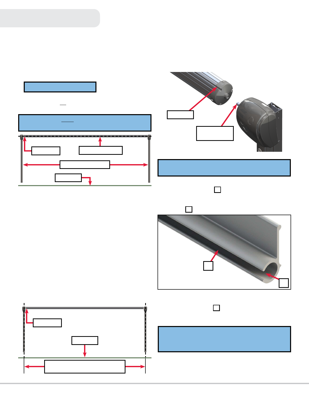
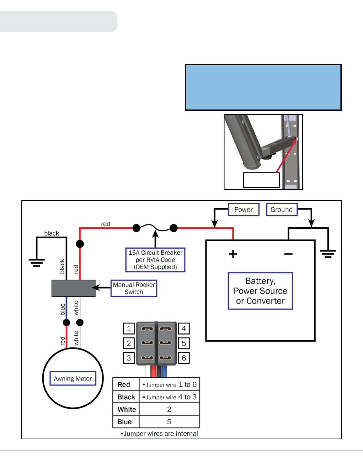
The Velarium Power Awning features an internal motor to steadily
operate the awning. Additionally, the pitch arm assembly allows
for rain dump and adjustable pitch features. The pitch arm
assembly also provides added stability.
Prior to Installation
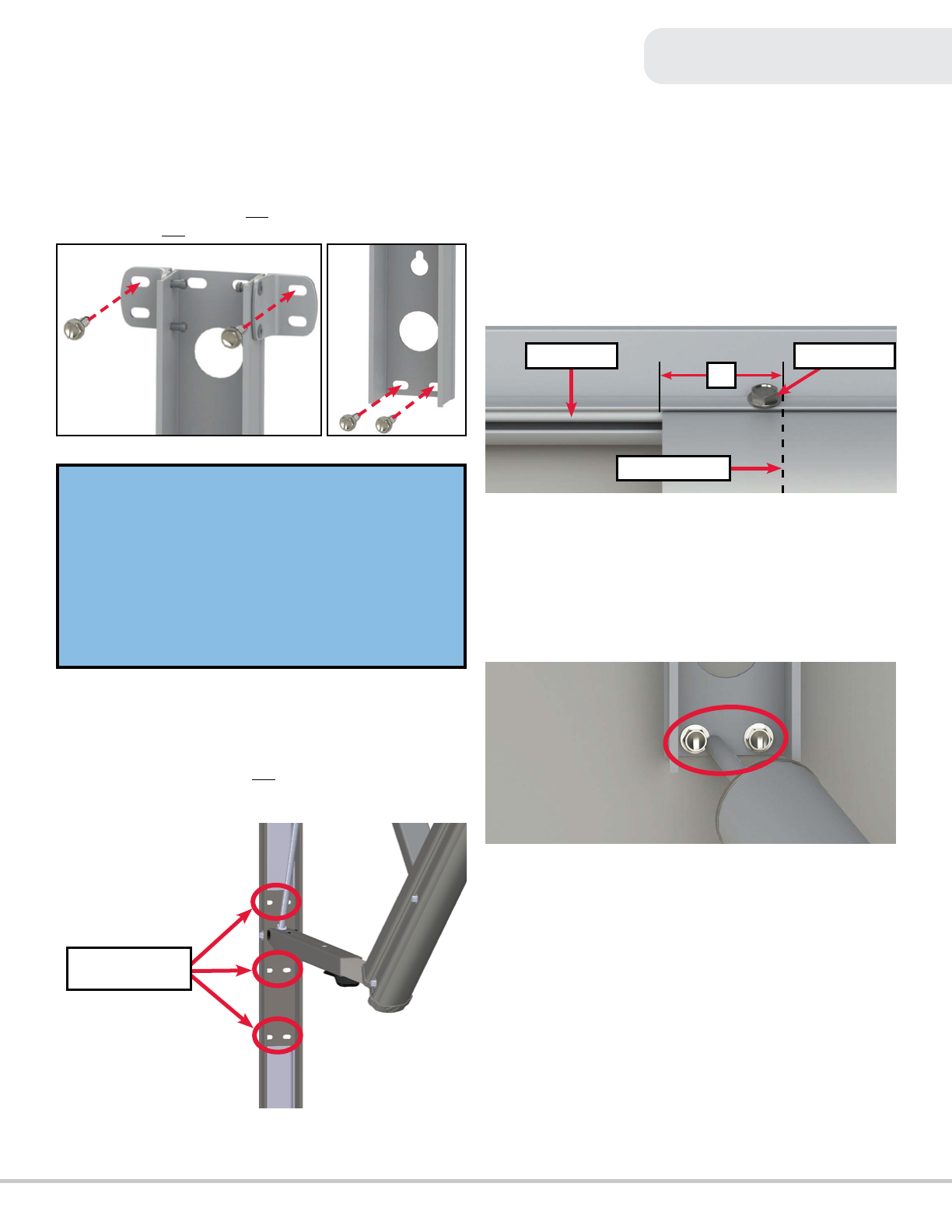
All screws supporting the awning assembly
must
have a backer
within the structure of the wall of the unit. Refer to the unit’s
manufacturer for proper location.
Resources Required
2-3 people #10 x ¾” screws
Cordless/electric drill #12 x 1¼” screws
Appropriate drive bits Wire cutters/strippers
Rivet gun (if needed) Non-permanent marker/pen
Screwdriver Silicone sealant or tape
#6 x ½” Hex-head screws Silicone lubricant
Introduction
Read all instructions before using the Velarium Power Awning. Airxcel
is not liable for damage resulting from failing to follow instructions
contained in this, and any other Velarium documentation relevant to
this product.
Safety
• Read this user manual before using the Velarium Power Awning to
reduce the risk of injury to persons or damage to the equipment.
• The product identity label contains specications of the unit, to
what standard it has been tested, and important safety notices.
• For your safety, ALL repairs and/or maintenance of unit should be
performed by your dealer or a qualied service technician.
• Failure to follow all instructions and safety warnings exactly as
described herein could result in serious injury, death, or property
damage.
• If the user of this awning fails to maintain it in the condition in
which it was shipped from the factory, or if the awning is not used
solely for its intended purpose, or if awning is not maintained
properly, then the risk of a re and/or risk of increases which can
cause personal injury, property damage, or death.
NOTE: Contact your Authorized Service Center or
Airxcel if you have any questions
before
starting any
operation, service, or maintenance.
Service and maintenance must be performed by a qualied
installer or technician, service agency.
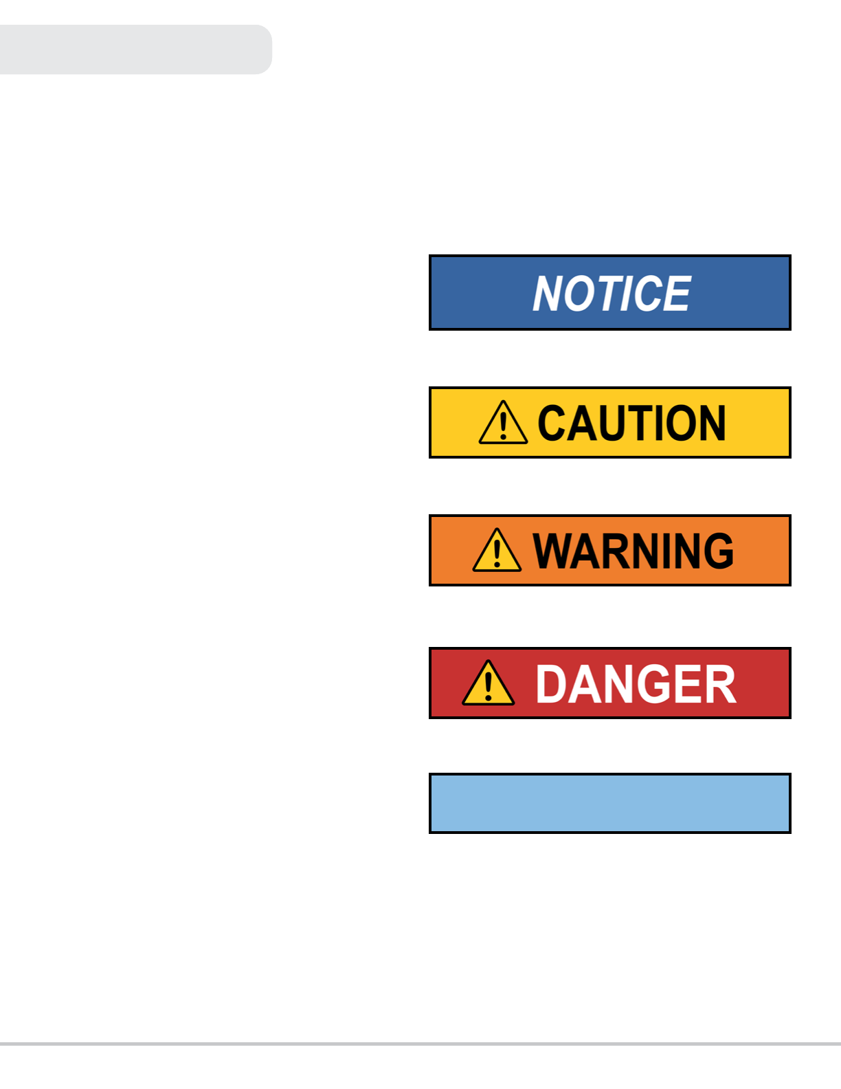
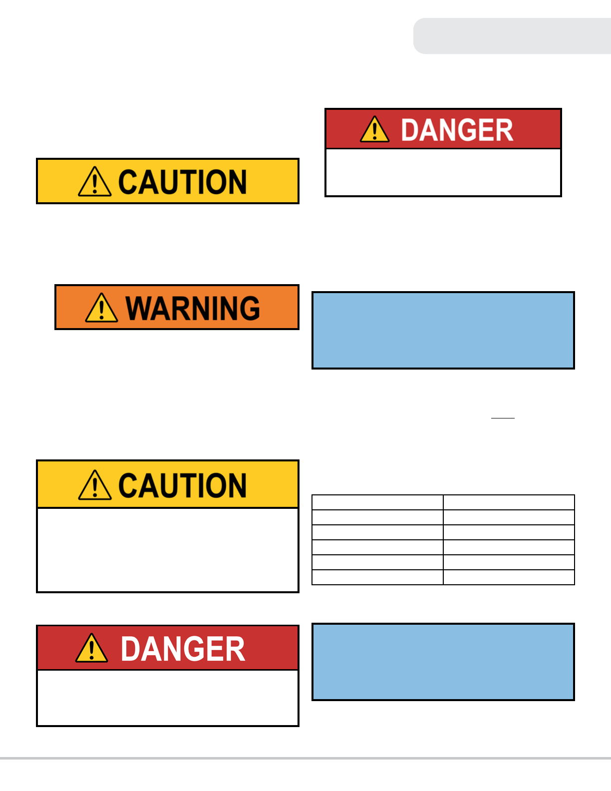
FIRE OR EXPLOSION HAZARD
Failure to follow safety warnings
exactly
could result
in property damage, serious personal injury, or death.
ELECTRIC SHOCK
Before installation or service, make sure the power has
been turned off at the circuit breaker panel.
INJURY/DAMAGE
This manual provides operational procedures for Velarium
Power Awning. Operating the Velarium Power Awning in
any other manner than described may result in personal
injury, damage to the unit or the awning assembly as well
as voiding the Velarium Limited Warranty.
NOTE: This manual will refer to the “drive side” or “idler
side” throughout for various instructions. The “drive side” is
the right-hand side of the awning when facing the awning
from the exterior of the unit. The “idler side” is the left-hand
side of the awning when facing the awning from the exterior
of the unit.

Service Log
©Velarium, an Airxcel Brand® Power Awning Installation Guide
230913
p. 4
3. Insert the drive head assembly shaft into end cap (Figure
3). Align the holes and secure with waxed screw. Repeat
process for idler head assembly at opposite end of roll tube.
4. Use a screwdriver to spread open either end of the awning
rail channel - Figure 4 A.
5. To protect the fabric from damage during installation, le
any sharp edges or burrs from the awning rail channel -
Figure 4 B.
6. Use silicone lubricant and spray the inside of the awning
rail channel (Figure 4 B).
7. Remove the tape from the fabric. Unroll a small portion of
fabric.
8. Slide the poly-cord into the awning rail channel and walk
the support arm assemblies and fabric down the awning
rail channel until the support arm assemblies are in line
with the centerline marks.
Awning Installation
Installation
Awning Rail Installation (if needed)
1. Position the awning rail along the line where the roof
and wall meet
OR
for pitched awnings: position the rail a
minimum of 6” above doors or windows.
2. After determining the awning rail’s proper location, mark its
position with a non-permanent method of marking.
3. Seal the back of the awning rail with silicone sealant or
tape.
4. Align the awning rail on the wall and secure with #10 x ¾”
screws, using all fastener holes.
Awning Installation
1. On the awning rail, mark the position of the centerlines of
the support arm assemblies. Make sure that the support
arm assemblies will not interfere with any lights, vents or
other obstructions.
2. Using a non-permanent marker/pen, mark a perpendicular
line from the awning rail down to the oor line. This is the
centerline of the support arm assembly (Figure 2).
NOTE: Awning rail not included.
NOTE: Awning rail MUST be level and parallel with the oor
line of the unit (Figure 1).
Figure 1
Roll Tube Assembly
Awning Rail
Support Arm Assembly
Floor Line
Figure 2
Awning Width is from Centerline to
Centerline of Support Arm Assemblies
Floor Line
Awning Rail
NOTE: To avoid compromising the structural integrity of the
wax screw, do not fully fasten the wax screw.
End Cap
Drive Head
Assembly Shaft
Figure 3
A
B
Figure 4
NOTE: The next steps will require three people: One to feed
the poly-cord into the awning rail channel; two to walk the
support arm assemblies along the awning rail while the
fabric slides into position.

Service Log
©Velarium, an Airxcel Brand® Power Awning Installation Guide
230913
p. 5
Securing the Fabric
9. Lift the support arm assembly up and secure by setting the
awning assembly to the desired height and attaching it to
the side of the unit with two #14 x 1 ¼” screws at the top
(Fig. 5) and two #14 x 1 ¼” screws at the bottom (Fig. 6).
10. Cut the zip ties and connect the wires from the drive head
assembly to a power source and run the awning half way
out.
• Remove the wire cover to expose the fastening points.
• Install the remaining two #14 x 1 ¼” screws at any of
the three locations shown (Figure 7) in the center of
the support arm.
11. Repeat this process for the opposite side of the awning
assembly.
Securing the Fabric
1. Extend and retract the awning several times to make sure
the fabric is square on the roll tube.
2. Secure the fabric in the awning rail no more than 1” inside
the edge of the fabric on both ends using a #6 x ½” hex-
head screw. Install the screw down through the awning rail
into the fabric and the poly-cord (Fig. 8).
Seal Wall Penetrations
1. Seal all fastener locations and wire penetrations with
silicone sealant to protect against water intrusion (gure 9).
2. Reinstall all wire covers onto the support arm assemblies.
NOTE: Make sure the awning assembly is square on the unit
prior to mounting the bottom two screws.
NOTE: Best practice for setting the awning height is to push
the top of the support arm assemblies up to be ush with the
bottom of the awning rail. The awning height can be adjusted
lower if desired, but make sure that the distance from the
awning rail to the top of the support arm assemblies is
consistent at both ends of the awning.
NOTE: Four rivets with 3/16” grip range can be used in place
of the two middle and two lower screws on laminated walls.
Figure 5 Figure 6
Possible Fastener
Locations
Figure 7
1”
Awning Rail #6 Hex Screw
Fabric Stitching
Figure 8
Figure 9

Service Log
©Velarium, an Airxcel Brand® Power Awning Installation Guide
230913
p. 6
Awning Wiring
Awning Wiring
Velarium Power Awning motors come stock with an internal 6A
auto reset breaker. If this breaker trips, it will take approximately
30 seconds to reset. Velarium recommends the awning be
wired into a 15A circuit breaker.
All wire shall be 14 AWG or higher as necessary to provide 11.5V
minimum at all times to the supplied power cable connection.
1. Pull the wires from the unit through the support arm
assembly. These wires may be located at the bottom or the
top of the support arm assembly.
2. Connect wiring from the unit to the switch and the awning
drive head per the wiring diagram (Figure 11).
Wiring Diagram
NOTE: If the awning is running in reverse of what the switch
indicates, check the switch and reverse the wires.
NOTE: Make sure all wires are routed on the outside of the
pin that secures the pitch arm to the mount arm (Figure 10)
to prevent pinching of the wires.
Wires Routed
Outside Pin
Figure 11
Figure 10

©Velarium, an Airxcel Brand® Power Awning Installation Guide
230913
Service Log
p. 7
One Year Limited Warranty
Velarium Awnings
one
Dura�on
Velarium’s warranty
What is Covered Under this Warranty
extrusions
.
• or
•.
•
items .
What is Not Covered Under this Warranty
•owner’s manual.
•
•
•.
•Velarium.
•
•whose serial num
•-
•
•
•
If You Have a Product Issue and Poten�al Warranty Claim:
1.
2.
3.
1136
45616
FOR FUTURE REFERENCE, YOU SHOULD RECORD THE FOLLOWING INFORMATION:
PART NUMBER:
SERIAL NUMBER:
DATE OF PURCHASE:
Warranty
Table of contents
Popular Lawn And Garden Equipment manuals by other brands

Brigmton
Brigmton BMQ-10-N-V instruction manual

Acorn Safety
Acorn Safety S0001 Installation, operation and maintenance instructions

BIOLAN
BIOLAN 220eco Instructions for installation, use and maintenance

Anova
Anova VAR700 Installation instructions & user manual

Kooper
Kooper 5902374 User instructions

Rowlinson Garden Products
Rowlinson Garden Products Eaton Summerhouse Assembly instructions